

Page 1
Installation Guide
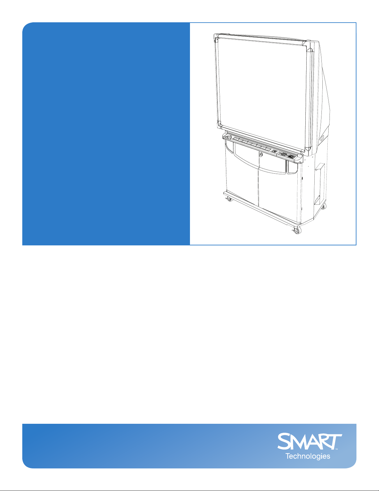
Rear Projection SMART Board™ 4000i
Interactive Whiteboard
Page 2

Registration Benefits
In the past, we’ve made new features available as free software upgrades.
Register your SMART product to be notified of free upgrades like these.
Keep the following information available in case you need to contact
Technical Support:
Serial Number
Date of Purchase
Register online at www.smarttech.com/registration
FCC Warning
This equipment has been tested and found to comply with the limits for a Class A digital device, pursuant to Part 15 of the FCC Rules.
These limits are designed to provide reasonable protection against harmful interference when the equipment is operated in a commercial
environment. This equipment generates, uses and can radiate radio frequency energy and, if not installed and used in accordance with the
manufac turer’s instructions., may cause harmful interference to radio communications . Operation of this equipment in a residential area is
likely to cause harmful interference in which case the user will be required to correct the interference at his own expense.
Trademark Notice
SMART Board, smarttech, Notebook, DViT, LinQ, X-Port and the SMART logo are trademarks of SMART Technologie s Inc. Windows is either
a regis tered trademark or a trademark of Microsoft Corporation in the U.S. and/or other countries. Macintosh is a trademark of Apple
Computer Inc., registered in the U.S. and other countries. projectiondesign is a trademark of projectiondesign Norway as. All other thirdpart y product and company names may be the trademark s of their respective owners.
Copyright Notice
© 1992–2007 SMART Technologies Inc. All rights reserved. No part of this publication may be reproduced, transmit ted, transcribed, stored in
a retrieval system or translated into any language in any form by any means without the prior written consent of SMART Technologies Inc.
Information in this manual is subject to change without notice and does not represent a commitment on the part of SMART.
Portions of the sof tware that ships with this product are copyrighted by Intel Corporation.
Portions of the soft ware that ships with this product are copyrighted by ParaGraph, a business unit of Vadem. CalliGrapher® Copyright ©
1997–2005 ParaGraph, a business unit of Vadem.
U.S. Patent Nos. 5,448,263; 6,141,000; 6,326,954; 6,337,681; 6,741,267; 6,747,636; 6,803,9 06; 6,919,880; 6,947,032; 6,954,197; 6,972,401 and
7,151,533. Canadian Patent No. 2,058,219. European Patent No. 1,297,488. Other U.S., Canadian and foreign patents pending.
Printed in Canada 04 /20 07
Page 3
Important Information
Please read this manual carefully before setting up and using the Rear Projection SMAR T Board™
4000i interactive whiteboard.
WARNING
WARNING
WARNING
CAUTION
The projector inside the unit is a high brightness light source. Don’t look directly
into the beam of light. Prevent children from looking directly into the beam.
To reduce the risk of fire or electric shock, don’t expose this product to rain or
moisture.
(For European customers only)
Use the 4000i with European TN and TT power distribution systems only. The
4000i isn’t suitable for older, IT-type power distribution systems found in some
European countries. “This system (IT-type) is widely used isolated from earth, in
some installations in France, with impedance to earth, at 230/40 0V, and in Norway,
with voltage limiter, neutral not distributed, at 230V line-to-line.” (IEC 60950:1999)
Contact qualified personnel if you’re uncertain about the type of power system
available where you’re installing the 4000i.
The projector inside the 4000i has been designed for use under norma l operating
conditions only. Normal operating conditions are defined as product use that does
not exceed eight hours per day and 260 days per year. Exceeding these operating
conditions could cause projector damage. Damage caused by such extended use
won’t be covered by the product warranty.
Other Precautions
For operating safety and to avoid damage to the cabinet and its parts, please read the following
information carefully.
• Move the unit with care. Quick stops, excessive force and movement over uneven surfaces
can overturn the unit.
• If you transport the 4000i, ship it in an upright position only, and never lay it facedown. In
addition, ensure that the projector is secure, or remove the projector from the cabinet and
package it with as much padding as is reasonably possible to protect it from vibration and
shock.
• If you transport the 4000i over a long distance, completely repackage it using the original
packaging. This packaging was designed with optimal shock and vibration protection. If the
original packaging isn’t available, pack all the components with as much padding as
reasonably possible to protect them from vibration or shock.
• Clean the interactive whiteboard surface regularly so that dust doesn’t build up on the surface
and adversely affect the operation of the 4000i.
99-00582-20 REV A0 Important Information i
Page 4

• Don’t touch the rear surface of the screen or apply isopropyl alcohol, water or acetone to it.
These fluids will damage the diffusion coating, resulting in a permanent deterioration in display
quality.
• If you inadvertently smudge the rear surface of the screen, dab it carefully with a soft cloth and
alcohol-free glass cleaner. Don’t spray glass cleaner directly on the back of the screen; spray
it lightly on the cloth and then gently dab the rear surface until the marks are removed.
• The 4000i uses digital cameras located inside the screen frame. Don’t allow excess glass
cleaner to flow into the crack between the frame and the writing surface, because the cleaner
could damage these cameras.
• Lock the casters after you set up the cabinet so that it remains st ationary when in use.
• Avoid setting up and using the 4000i in an area with excessive levels of dust, humidity or
smoke.
• Avoid exposing the 4000i to extreme heat or cold. The operating temperature range is from
41°F to 85°F (5°C to 29°C) with up to 80% humidity (non-condensing). The shipping and
storage temperature range is from 14°F to 95°F (-10°C to 35°C) with up to 80% humidity
(non-condensing).
• Make sure there is a power outlet near the 4000i that remains accessible during use.
• Use safe practices when you’re connecting the 4000i power cord to a power outlet. For
example, make sure your hands are dry and don’t insert the plug into a dusty outlet.
• If possible, disconnect the 4000i’s power cord from the power outlet before thunderstorms.
However, don ’t touch the 40 00i or its power cord during a thunderstorm, because you may be
at risk of electrical shock.
• If you won’t use the 4000i for an extended period, disconnect the unit’s power cord from the
power outlet.
• Disconnect the 4000i’s power cord from the power outlet before you install or service any
components.
• This 4000i comes with a three-prong, grounding-type power plug (designed to fit into a
grounding-type power outlet). If you can’t insert the plug into a power outlet, contact an
electrician to replace the power outlet. Don’t modify the power plug.
• Don’t modify the power cord. Handle it carefully and avoid bending it excessively. Don’t place
the power cord in an area where it’s likely to be stepped on or pinched by items placed on or
against it. If you must run a cable over the floor, lay it in a flat, straight line, and secure it to the
floor with tape or a cable management strip of contrasting color.
• If your 4000i requires replacement parts, use the parts that are specified by SMART
Technologies Inc.
ii Important Information 99-00582-20 REV A0
Page 5

Table of Contents
Important Information i
Other Precautions...................................... ... ... ................................................. ... ... ..........................i
About the 4000i 1
4000i Features.............................................. ... ... .... ... ... ... .... ... ........................................................ 1
The projectiondesign F20 Projector................................................................................................ 1
Pen Tray Features ......................................................................................................................... 2
Control Panel ................................................................................................................................. 2
Connection Panel... ... .... ... ... ... .... ... ... ... .... ... ... ................................................ .... ... ... ... .... ... .............. 3
Main Power Input and Power Outputs ............................................................................................ 4
Setting Up the 4000i 5
Positioning the 4000i....................................................................................................................... 5
Installing and Connecting a Computer ..........................................................................................6
Connecting to a VCR and/or DVD Player ....................................................................................... 7
Connecting a Printer .............. .... ... ... ... .... ... ... ................................................ .... ... ... ... .... ... .............. 9
Connecting the 4000i to a Network............... ... ... .... ... ... ... .... ................................................ ... ... ...10
Connecting an External Sound System ........... ... .... ... ... ... .... ... ... ... .... ... ... ... ... .... ............................ 10
Connecting a Guest Laptop .......... ... ... .... ... ... ... ... .... ... ................................................ .... ... ... ... ...... 10
Finalizing the Installation 13
Configuring the Computer Settings...............................................................................................13
Selecting the Projector’s Picture Settings..................................................................................... 14
Adjusting the Projected Image...................................................................................................... 14
Installing SMART Board Software.................................................................................................17
Configuring the Computer Port ..................................................................................................... 18
Orienting the Interactive Whiteboard............................................................................................. 18
Basic Operations 19
Turning On the 4000i .................................................................................................................... 19
Switching the 4000i to Standby Mode. .... ... ... ... .................................................... ......................... 21
Turning Off the 4000i..................................................................................................................... 22
Using the SMART Board Interactive Whiteboard.......................................................................... 22
Changing the Projector’s Display Source ................................................................................... 24
Adjusting the Volume.................................................................................................................... 25
Maintaining the 4000i 27
Cleaning the Screen and Other Components............................................................................... 27
Cleaning the Projector................................................................................................................... 28
Replacing the Projector Lamp .... ... ... ... .... ... ... ... ............................................................................. 28
Restoring Projector Settings ......................................................................................................... 29
Calibrating the Cameras ............................................................................................................... 29
Appendix A: Removing and Replacing the Projector 31
Appendix B: Connecting Rack-Mount Equipment to the Projector Platform 33
99-00582-20 REV A0 Table of Contents iii
Page 6

Customer Support 35
Online Support.............................................. ... ... .... ... ... ... .... ... ... ... ................................................ 35
Training......................................................................................................................................... 35
Contacting SMART Technical Support.......................................................................................... 35
General Inquiries................................................. .... ... ... ... .... ... ...................................................... 35
Registration................................................................................................................................... 35
Sending Feedback........................................................................................................................ 36
Waste Electrical and Electronic Equipment Regulations 37
Index 39
iv 99-00582-20 REV A0
Page 7

About the 4000i
The 4000i is a Rear Projection SMART Board interactive whiteboard cabinet with an integrated
liquid crystal display (LCD) projector and a 66" (167.6 cm) diagonal interactive screen.
A mirror system in the cabinet reflects the projected image onto the back of the interactive
whiteboard screen, eliminating the shadows that may occur in a front projection system.
You can switch between different projector input sources (host comp uter, VCR, DVD player and
guest laptop) with the press of a control panel button.
DViT™ (Digital Vision Touch) technology uses digital cameras to track objects on the interactive
whiteboard. Each camera recognizes the position of a pen tray tool or your finger on the screen
and sends this information to the computer for processing. You can perform normal computer
operations, such as opening and closing applications, scrolling through files and opening your
browser by touching the screen.
4000i Features
• Touch sensitive, rear projection interactive whiteboard that you can use like a standard
computer. You can write over any application in digital ink using a pen tray pen or your finger
and save your digital ink notes as a Notebook™ software file for reference and distribution.
• Integrated projectiondesign® F20 projector with short-throw lens.
• Audio system.
• Pen tray (including four pens and an eraser), a wireless keyboard and a wireless mouse.
• Control panel with projector, volume and source switching controls. The control panel also
provides button-press access to Note bo ok software an d F loa tin g Tools.
• Connection panel at the rear of the cabinet that allows you to connect a network cable, prin ter
and room audio system.
• Locking front doors for enhanced security.
• Minimal floor space requirements: the 4000i fits through most standard doorways for room-toroom mobility.
The projectiondesign F20 Projector
The F20 projector has SXGA+ resolution (1400 × 1050 pixels) an d is adapted for us e in the 4000i.
NOTE: See page 14 for information on adjusting the projected image.
99-00582-20 REV A0 About the 4000i 1
Page 8
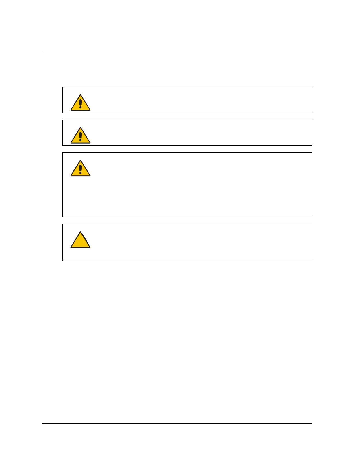
Pen Tray Features
Eraser
Pen Tray Pens
Control Panel
Pen Tray
Pen Tray Buttons
Using a pen tray pen, you can write over the computer image with digital ink. You can use SMART
Board software to change any of these pens to high lighters, assign a new color , or alte r their width.
You can also change the eraser’s size.
The top pen tray button opens the SMART Keyboard for on-screen typing. The bottom button
makes your next contact with the interactive whiteboard a right- click. You can also configure these
buttons to perform other functions .
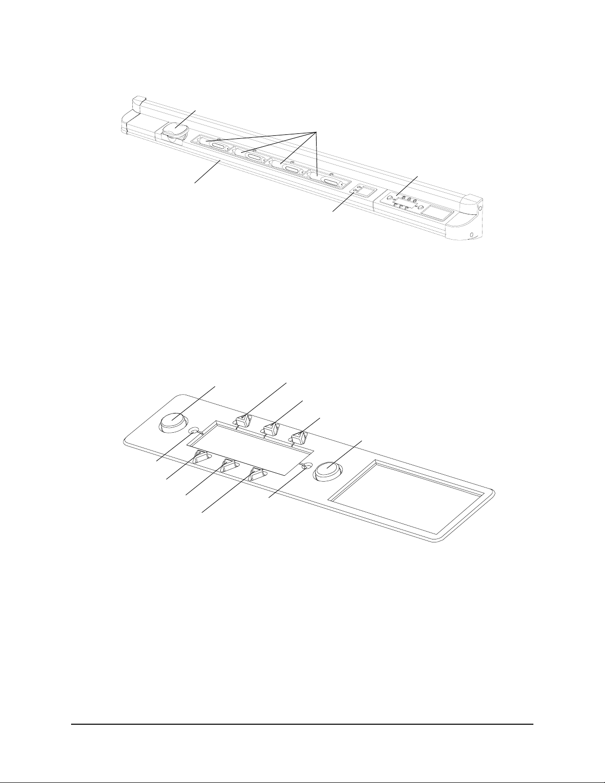
Control Panel
Volume Up
Internal Computer
Guest Laptop
Lamp Off
On LED
Volume Down
VCR/DVD Player
Notebook Software
Lamp On
Off LED
You can use the control panel to start the 4000i, put the 4000i into Standby mode, change the
display source of the projector, adjust the volume of the internal sound system and start Notebook
software.
2 About the 4000i 99-00582-20 REV A0
Page 9
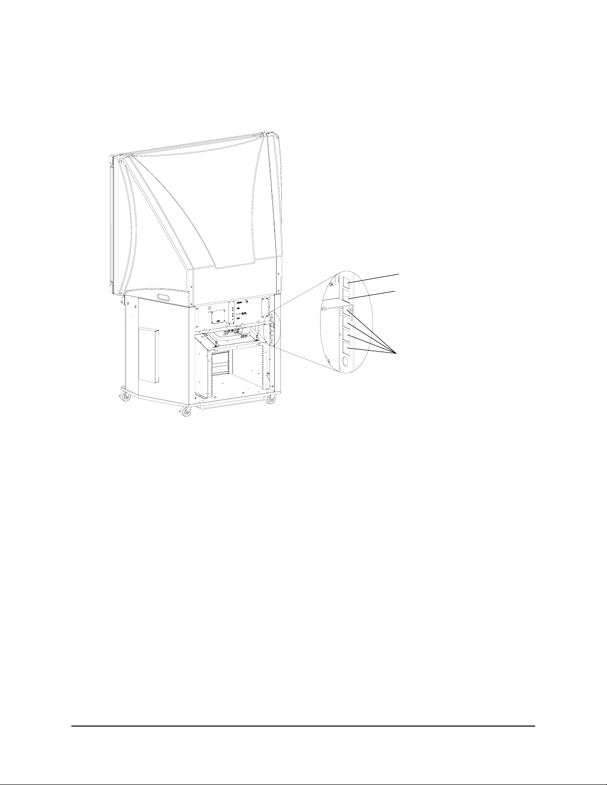
Connection Panel
You can use the connection panel to make a variety of external connections to the 4000i cabinet.
1
7
6
8
5
3
4
2
3
1. Printer (Female) – Enables connection to an external printer. See page 9 for more
information.
2. Network – Enables connection to a network. See page 10 for more information.
3. VCR/DVD Audio OUT – These cables are already linked with an RCA cable to the Audio IN
jacks on the connection panel. Keep the right and left channel connections correct for stereo
sound.
4. Computer 2 Video IN (Female) – Used to connect a guest laptop. See page 10 for more
information.
5. Computer 2 Audio IN (Female) – Used to connect a guest laptop. For more information, se e
page 10.
6. Audio IN – These connectors are already linked with an RCA cable to the VCR/DVD Audio
jacks on the connection panel. Keep the right and left channel connections correct for stereo
sound.
7. Room Audio OUT – Enables connection to an external sound system. See page 10 for more
information.
8. Computer 2 Serial IN (Female) – Used to connect a guest laptop. See page 10 for more
information.
99-00582-20 REV A0 About the 4000i 3
Page 10
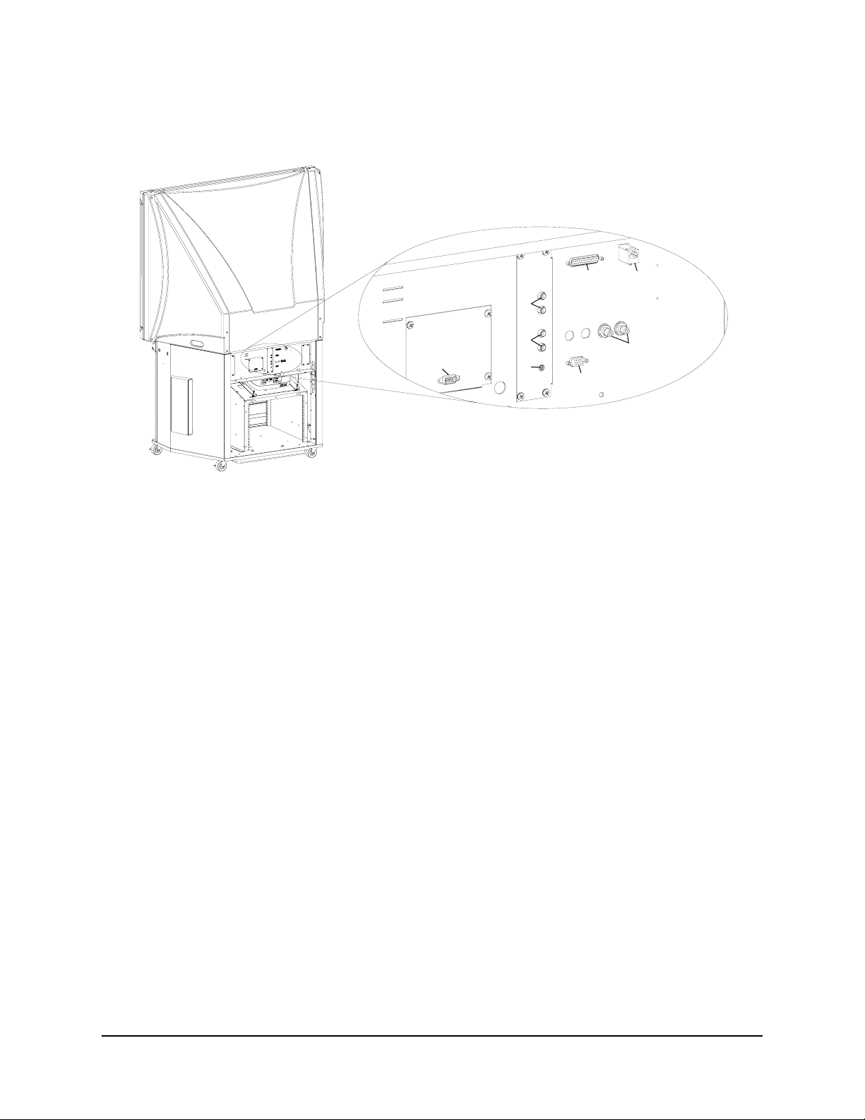
Main Power Input and Power Outputs
The Main Power IN and Power OUT connections are located to the right of the connection panel
(when you face the rear of the cabinet).
NOTE: The power
connections on your 4000i
may be arranged differently
from what is illustrated in
this diagram.
Main Power IN
Laptop Power OUT
Computer and Peripherals
Power OUT (×4)
Main Power IN – Provides power power to the 4000i cabinet from a wall receptacle.
Laptop Power OUT – Provides power to a guest laptop.
Computer and Peripherals Power OUT – Provides power output to other devices inside the
4000i cabinet. You can use these cables for the internal computer, projector and peripherals, such
as VCRs, DVD players and printers.
4 About the 4000i 99-00582-20 REV A0
Page 11
Setting Up the 4000i
Use this section of the manual to learn how to:
• position the 4000i (this page)
• install and connect the computer (page 6)
• connect a VCR or DVD player (page 7)
• connect a printer (page 9)
• connect a guest laptop (page 10)
• connect a network (page 10)
• connect an external sound system (page 10)
Positioning the 4000i
1. Remove the interactive whiteboard from its shipping carton.
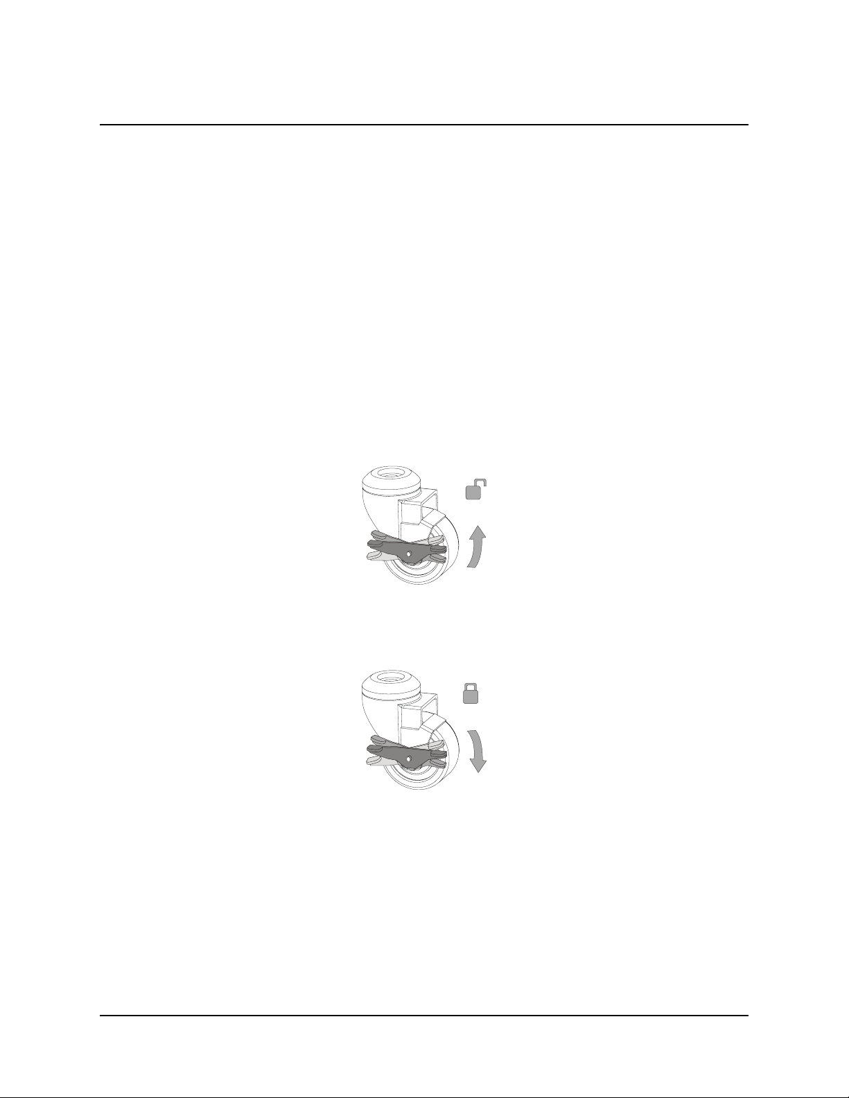
2. Unlock the casters by pressing up on the caster-lock tab.
3. Move the 4000i to its required location. Leave enough space around the unit to comfortably
perform assembly and connection procedures.
4. Lock the casters by pressing down on the caster-lock tab.
99-00582-20 REV A0 Setting Up the 4000i 5
Page 12
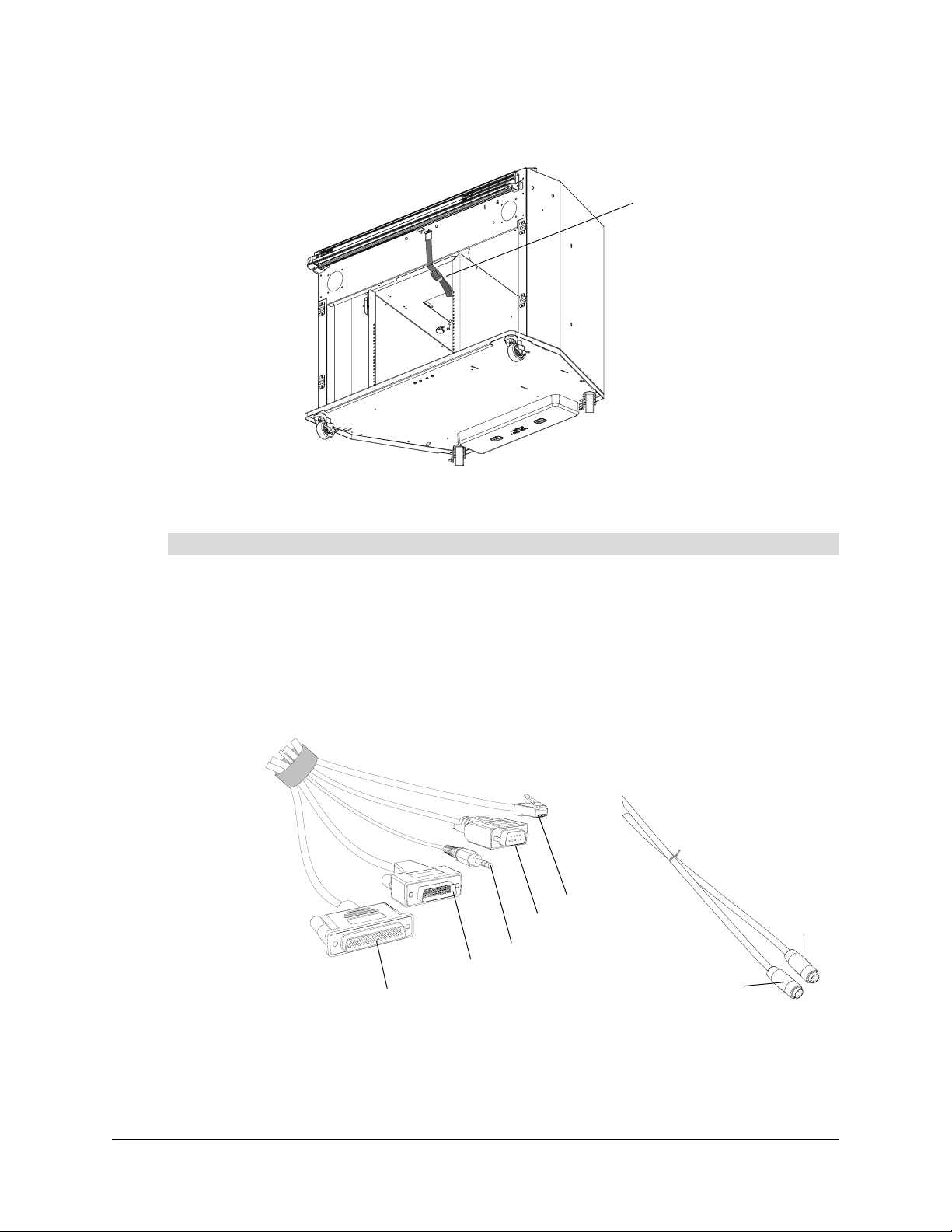
5. Open the cabinet’s front doors. Unbuckle and remove the strap that secures the small mirror
located in the middle of the speaker panel, below the projector platform.
Remove this strap.
Installing and Connecting a Computer
To install and connect a computer
1. While facing the front of the cabinet, slide the computer into place at the ri ght-han d side of the
cabinet, above the computer straps. Use the straps to secure the computer.
NOTE: The computer straps enable you to roll the cabinet from room to room without having
to remove the computer. However, these straps won’t secure the computer during cabinet
shipment. If you need to transport the 4000i, remove the computer before you ship it.
2. Locate the tie-wrapped bundle of cables dangling inside the cabinet. There are also power,
keyboard and mouse cables located nearby.
Network
Printer
Serial
Audio
Video
Keyboard
Mouse
6 Setting Up the 4000i 99-00582-20 REV A0
Page 13
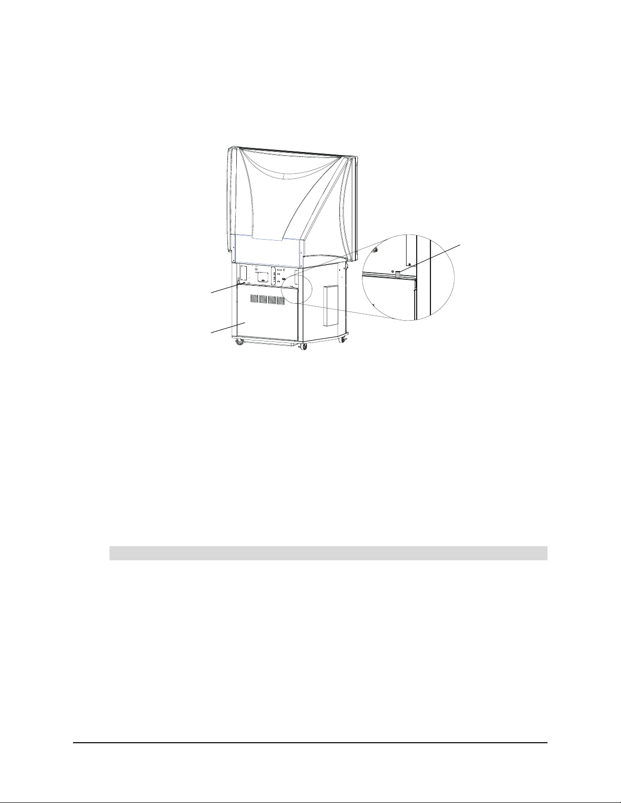
NOTE: You can remove the 4000i’s rear access panel if you need greater access to the
computer’s connection panel. To remove the rear access panel, loosen the two captive
thumbscrews at the top of the rear access panel. Rotate the top of the rear access panel
toward you and then pull it up, releasing it from the cabinet. Reatt ach th e rear access p an el to
the back of the cabinet after you turn on the projector and internal computer.
Captive
Thumbscrew
Captive Thumbscrew
Rear Access Panel
3. Connect the Computer 1 Video cable to the computer’s DVI connector.
4. Connect the Computer 1 Audio cable to the computer’s audio line OUT connector.
5. Connect the Computer 1 Serial cable to an available serial connector on the computer.
NOTE: If the computer doesn’t have an available serial receptacle, connect the provided
SMART USB adapter between the Computer 1 Serial cable and the computer’s USB
receptacle.
6. Connect the Printer cable to the computer’s DB25 (printer) connector.
7. Connect the Network cable to the computer’s network adapter (if applicable).
8. Connect the Mouse and Keyboard cables to the computer’s PS/2 mouse receptacle and the
PS/2 keyboard receptacle.
9. Connect the AC Power cable to the computer’s power connector.
To connect the power cable
1. Connect the power cable in the accessory box to the power inlet at the rear of the 4000i.
2. Connect this power cable to an available power outlet.
Connecting to a VCR and/or DVD Player
You can connect a VCR to the projector, using either the composite video cable or the S-video
cable bundled inside the cabinet. To connect a DVD player to the projector, use the S-video cable
bundled inside the cabinet. You can then switch the display source to the VCR or DVD player by
pressing the VCR/DVD Player button on the 4000i’s control panel.
99-00582-20 REV A0 Setting Up the 4000i 7
Page 14

If you want to connect both a VCR and a DVD player to the pr ojector, you must use the composite
video cable for the VCR and the S-video cable for the DVD player . If b oth are co nnected, pr essing
the VCR/DVD Player button alternates the display source between the VCR and the DVD player.
There is a three-second delay before the alternate display source appears.
Although there is only one external audio conn ection, you can lin k the VCR and DVD pla yer audio
connections to automatically use the audio signal from the active video source.
When you switch to another video source (such as the internal computer) and then press the
VCR/DVD Player button, the last active video source appears.
To connect a VCR to the 4000i
1. Connect an RCA composite video cable inside the cabinet to the VCR’ s video output jack. This
jack may be labeled To Monitor.
NOTE: If the VCR has an S-video output, you can connect the S-video cable bundled inside
the cabinet to the VCR. However, if you use the S-video cable to connect to the VCR, you
won’t be able to use this cable to connect to a DVD player.
2. Connect the RCA cables inside the cabinet to the VCR’s RCA Audio (may also be labeled
Audio OUT) outputs. Keep the right and left channel connections correct for stereo sound.
NOTE: You can’t connect these audio cables to both the VCR and the DVD player. However,
you can link the audio connections of the DVD playe r and VCR (se e page 9 for more
information).
3. Connect the VCR’s power cable to an available power outlet in the cabinet.
To connect a DVD player to a 4000i
1. Connect the S-video cable inside the cabinet to the DVD player’s S-video OUT receptacle.
NOTE: Alternatively, you can connect the RCA composite video cable bundled inside the
cabinet to the DVD player. However, the S-video cable provides better image quality than the
composite video cable.
2. Connect the RCA audio cables inside the cabinet to the DVD player’s RCA Audio (or Audio
OUT) outputs. Keep the right and left channel connections correct for stereo sound.
NOTE: You can’t connect these audio cables to both the VCR and the DVD player. However,
you can link the audio connections of the DVD playe r and VCR (se e page 9 for more
information).
3. Connect the DVD player’s power cable to an available power outlet in the cabinet.
8 Setting Up the 4000i 99-00582-20 REV A0
Page 15
To link the VCR and DVD player audio connections
1. If there is a tape in the VCR, remove it.
2. Connect standard RCA audio cables (not supplied) from the DVD player’s RCA Audio (or
Audio OUT) outputs to the VCR’s RCA Audio (or Audio IN) inputs. Keep the right and left
channel connections correct for stereo sound.
3. Connect the RCA audio cables bundled inside the ca binet to the VCR’ s RCA Audio (or Audio
OUT) outputs. Keep the right and left channel connections correct for stereo sound.
When you switch video sources, the audio source for the cabinet speakers changes with it. If
the audio source doesn’t switch along with the video source, refer to the instructions you
received with the VCR for additional setup procedures.
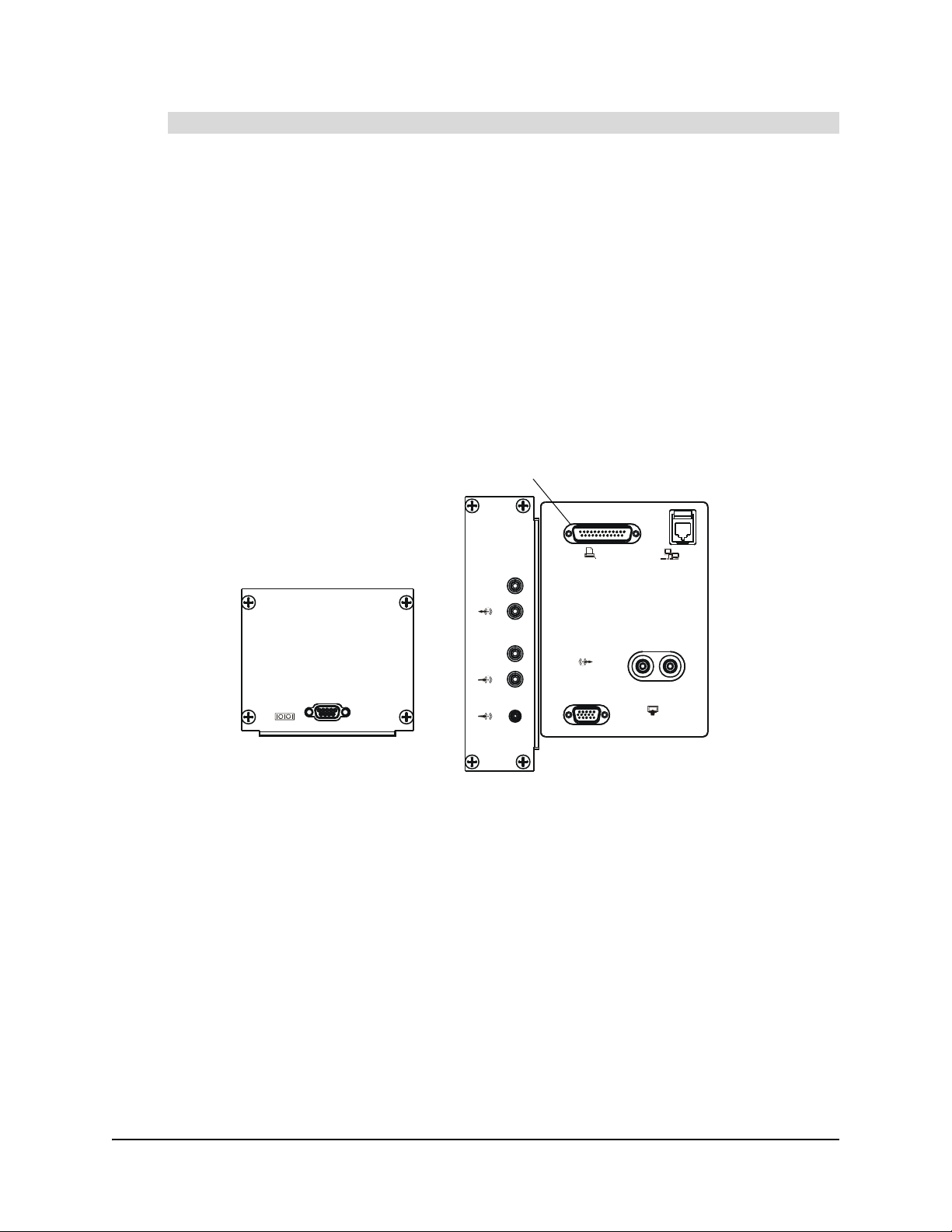
Connecting a Printer
Connect a DB25 printer cable (not supplied) from the printer to the Printer Connector receptacle
on the connection panel.
Printer Connector
Computer 2 Serial
Audio OUT
Audio IN
VCR/DVD Audio OUT
Printer
Network
Output
RL
Computer 2 Inputs
99-00582-20 REV A0 Setting Up the 4000i 9
Page 16

Connecting the 4000i to a Network
Connect a standard male-to-male RJ45 networ k cable (not supplied ) from the network cable outlet
to the Network IN receptacle on the connection panel.
Network IN
Printer
Audio OUT
Audio IN
VCR/DVD Audio OUT
Computer 2 Serial
Network
Output
RL
Computer 2 Inputs
Connecting an External Sound System
Connect standard RCA audio cables (not supplied) from the external sound system’s RCA Audio
Inputs to the two Audio OUT (L/R) jacks on the connection panel. Keep the right and left channel
connections correct for stereo sound.
Audio OUT
Printer
Network
Audio OUT
Audio IN
VCR/DVD Audio OUT
Computer 2 Serial
Output
RL
Computer 2 Inputs
Connecting a Guest Laptop
With the guest laptop shelf, you can connect a laptop computer to the 4000i and switch the source
of the 4000i’s data input between the internal computer and the guest laptop.
10 Setting Up the 4000i 99-00582-20 REV A0
Page 17

To connect a guest laptop
1. Connect the included bundle of laptop connection cables to the corresponding re ceptacles on
the 4000i’s rear panel.
Laptop video input
Printer
Network
Laptop sound input
Laptop serial input
Computer 2 Serial
Audio OUT
Audio IN
VCR/DVD Audio OUT
Output
RL
Computer 2 Inputs
2. Connect the other end of the laptop connection cables to the appropriate receptacles on the
guest laptop.
NOTE: Most modern laptops have USB 2.0 receptacles instead of a DB9 serial receptacle.
The 4000i includes a DB9 serial to USB converter cable in the bundle of laptop cables.
99-00582-20 REV A0 Setting Up the 4000i 11
Page 18

12 Setting Up the 4000i 99-00582-20 REV A0
Page 19

Finalizing the Installation
Use this section of the manual to learn how to:
• configure the computer settings (this page)
• select the projector’s picture settings (page 14)
• adjust the projected image (page 14)
• install SMART Board software on the connected computer (page 1 7)
• configure the computer port (page 18)
• orient the interactive whiteboard (page 18)
NOTE: Turn the 4000i and host computer on before proceeding (see Turning On the 4000i on
page 19).
Configuring the Computer Settings
For optimal configuration, use the following recommended settings for the computer inside the
4000i cabinet.
Recommended Settings
Set the computer to turn off the monitor after one hour of inactivity and to switch the hard disk(s) to
Standby mode after two hours. This prevents the computer from unexpectedly switching to
Standby mode while you’re presenting.
When the 4000i’s active display source is the comp uter, the computer stops sending an RGB
video signal to the projector after the set period of inactivity. After approximately five minutes with
no RGB signal, the projector switches to Standby mode.
NOTE: If the projector’s input source is the video source (either composite or S-video), the
projector won’t switch to Standby mode.
To change the settings in the Windows® operating system, double-click the Power Options icon
in the control panel and adjust the settings in the Power Schemes tab. For Macintosh computers,
click the Energy Saver icon in the System Preferences application. For detailed information on
changing power management settings, see your computer’s operating system instructions.
Matching the Computer’s Resolution to the Projector Resolution
The projector resolution is 1400 × 1050 pixels (SXGA+) and you must ensure that the computer’s
resolution is the same. If the computer’s resolution is set to anything other than this optimal
resolution, you may not see the entire projected image, or the image may be too small to fill the
screen, even when you adjust it. For more information on changing the computer’s resolution, see
your computer’s operating system instructions.
NOTE: You may need to adjust the computer’s refresh rate to obtain the best results. Set the
computer to an initial refresh rate of 60 Hz and adjust this rate up or do wn u ntil you’ve de te rmined
the ideal refresh rate. For more information on changing the computer’s refresh rate, see your
computer’s operating system instructions.
99-00582-20 REV A0 Finalizing the Installation 13
Page 20

Selecting the Projector’s Picture Settings
The projectiondesign F20 projector has two picture quality settings. If you turn eco mode off, the
projector displays its brightest image, but this setting also reduces the life of the lamp. To display
an acceptable image without reducing the lamp’s life, turn eco mode on.
To select the projector’s picture setting
1. Press MENU on the projector’s remote control.
2. Select the dynamic menu.
3. Press the remote control’s arrow buttons to find and select the eco mode category.
4. Select on or off. The projector’s image quality changes to reflect your choice.
5. Press OK on the remote control to return to the main menu, and press menu on the remote
control to exit.
Adjusting the Projected Image
You may need to adjust the projector to display a focused image that fits on the screen. Complete
the following procedures only as required.
NOTE: Don’t adjust the image size and geometry based upon the projector’s splash screen. The
splash screen image is much smaller than the computer’s projected image. Make sure you set the
computer’s resolution and refresh rate (see page 13) before you adjust the projected image.
While making adjustments to the projected image, check both the reflection in the small mirror and
the actual image on the screen. For the best image, the reflection must be in the center of the
small mirror, and the gap on each side of the mirror’s image must be symmetrical.
Preparing the 4000i
To adjust the projector, you must first remove the rear access panel (see page 7). Use the 7/16"
nut driver included in the accessory kit to loosen the three locking bolts under the projector
platform.
Loosen these
three bolts.
14 Finalizing the Installation 99-00582-20 REV A0
Page 21

To move the image up or down
1. Loosen the upper thumbscrews on both sides of the small mirror. Don’t loosen the lower pivot.
2. Gently push the mirror away from you to lower the image, or pull it towards you to raise the
image.
Upper Thumbscrew
Pivot
(Do not loosen)
3. When you’ve finished adjusting the mirror, tighten the thumbscrews.
To adjust the focus
Gently and slowly turn the projector’s lens until the projected image appears cle arly on the 40 00i’ s
screen.
Gently turn this lens
to adjust the focus.
99-00582-20 REV A0 Finalizing the Installation 15
Page 22

To adjust the image laterally (side to side)
1. Loosen the two knobs on the bottom left side of the mounting plate and slide the projector to
the left or right.
If the projector won’t slide after you’ve loosened the two knobs, try slightly loosening the
spring-loaded knob on the right side of the projector plate. This right side knob also controls
the projector’s tilt (see To adjust roll on page 16), so be careful to only loosen this knob
enough to allow the plate to slide.
Loosen these
two knobs.
2. After you’ve adjusted the image, tighten the two knobs to lock the projector in place.
To adjust roll (the projector’s tilt)
1. Tighten or loosen the knob on the right side of the projector’s mounting plate until the
projected image is level on the screen.
Adjust this knob.
2. If you can’t tighten the knob on the right side of the projector’s mounting plate any further,
adjust the roll by slightly loosening the two knobs on the left side of the projector’s mounting
plate.
16 Finalizing the Installation 99-00582-20 REV A0
Page 23

To adjust the image size
1. Using the TR20 torx key included in the accessory kit, loosen the three bolts that attach the
projector to the projector plate.
Loosen these
three bolts.
2. Slide the projector backward to increase the image size or forward to reduce the image size.
3. Tighten the thre e bolts you loosened in step 1.
IMPORTANT
After you’ve adjusted the projector, use the 7/16" nut driver to tighten the three
locking bolts on the bottom of the projector’s mounting platform that you loosened
in Preparing the 4000i on page 14.
Installing SMART Board Software
You can install SMART Boar d sof tware o n any compute r using th e sof twar e CDs included with the
4000i.
TIP
During the installation, select the option to start the SMART Board tools
automatically when you start the computer. This ensures that the interactive
whiteboard is fully functional when you start the computer.
When SMART Board tools are open, the SMART Board icon appears in the notification area
(Windows computers) or in the Dock (Macintosh computers).
To install SMART Board software
99-00582-20 REV A0 Finalizing the Installation 17
Page 24

1. Turn the computer and the projector on.
IMPORTANT
2. Close all open applications on the computer.
3. Insert the SMART Board software CD into the CD drive.
– On Windows computers, the installation starts automatically. Follow the on-screen
instructions. If the CD doesn’t start automatically, select Start > Run, type x:\autorun.exe
(where x: is the CD drive), and press ENTER.
– On Macintosh computers, double-click the SMART Board Install CD icon that appears on
the desktop. Double-click the SMART Board Software icon and follow the on-screen
instructions. You may require an administrator’s password to complete the installation.
If you’re using a USB adapter to connect the interactive whiteboard to the
computer and the computer can’t find an appropriate driver, unplug the USB
adapter from the computer, install SMART Board software and then reconnect
the USB adapter.
If the Found New Hardware wizard appears, browse to the SMART Board
software CD so that the wizard can locate the correct driver.
Configuring the Computer Port
After you install SMART Board software and connect the interactive whiteboard, the screen
becomes fully interactive. However, sometimes SMART Board software can’t locate the port to
which the interactive whiteboard is connected.
If the screen isn’t touch sensitive, configure the port in SMART Board software. If the interactive
whiteboard is connected with a USB adapter, disconnect the USB connector from the computer,
wait ten seconds, and reconnect it. For more information, see the SMART Board software Help.
Orienting the Interactive Whiteboard
Although the interactive whiteboard is oriented by default, you may want to perform an orientation
to ensure that the computer accurately tracks contact with the screen. For more information, see
the SMART Board software Help.
18 Finalizing the Installation 99-00582-20 REV A0
Page 25

Basic Operations
Use this section of the manual to learn how to:
• start the 4000i (this page)
• switch the 4000i to Standby mode (page 21)
• turn off the 4000i (page 22)
• work with the interactive whiteboard (page 22)
• change the projector’s display source (page 24)
• adjust the volume (page 25)
CAUTION
The air vents that cool the 4000i’s projector and computer are located at the back
of the unit. Do not push the 4000i against a wall when it’s in use, or the vents will be
blocked and the unit can overheat.
Turning On the 4000i
If you haven’t done so already, turn on the computer.
If the 4000i is in Standb y mode, press the Lamp On button on the control panel to restore power to
the projector lamp.
Lamp On
99-00582-20 REV A0 Basic Operations 19
Page 26

To start the 4000i
Use the following table to restore the 4000i to a fully operational state.
What You See What You Should Do
The screen is black and
the Lamp On LED is
blinking intermittently
(short flashes between
long pauses)
The No Input message
appears and the Lamp
On LED is steadily
illuminated
The screen is black and
the Lamp On LED is
blinking slowly
The screen is black and
the Lamp Off LED is
blinking rapidly
The logon screen
appears
The Lamp On LED
continues to blink
intermittently, even
though you’ve pressed
the Lamp On button to
start the system
The Lamp Off and On
LEDs are both flashing
constantly
The projector is in Standby mode (with the lamp off).
Press the Lamp On button on the control panel. The Lamp On LED
indicator blinks quickly as the lamp warms up. After approximately 60
seconds, a No Input message appears or the screen is restored to its
last active state.
The projector lamp is on but you’ve selected an inactive display
source or the computer is off or in Standby mode.
Press a key on the connected keyboard to activate the computer.
OR
Press a source button on the control panel to select an active source.
If the No Input message remains, turn on the comp ut er or pr es s the
computer’s reset button, and log on as usual using the connected
keyboard.
The projector lamp is turning on, and the logon screen will appear
after approximately 60 seconds.
The projector lamp is in Reversible S t andby mode . If you don’t pre ss a
button to restore the image for three minutes, the On LED indicator
blinks slowly for 60 seconds as the lamp turns off and cools down. If
this happens, follow the instructions in the first row of this table to
restore the 4000i to an operational state.
The projector lamp is still on. You can log on as usual using the
connected keyboard.
Projector problems are preventing the projector lamp from warming
normally. Examine the projector status LED indicator, and then consult
the troubleshooting section of the projectiondesign F20 user’s guide.
The system can’t detect a projector. Review the projectiondesign
F20 user’s guide to make sure the projector is connected properly.
20 Basic Operations 99-00582-20 REV A0
Page 27

Switching the 4000i to Standby Mode
CAUTION
At the end of a session, log off from the computer (for security purposes), and switch the 4000i to
Standby mode to turn off the projector lamp and conserve the lamp’s life. Close and lock the
cabinet’s front doors for additional security.
To maintain normal operating conditions, switch the projector to Standby mode outside of normal,
daily (eight hour) operation. In Standby mode, the lamp is turned off and the projector r emains o n.
You can also configure the computer’s power management settings (see Configuring the
Computer Settings on page 13) to stop sending a video signal after a period of idle time. The
projector turns off when there is no video signal.
The projector inside the 4000i has been designed for use under norma l operating
conditions only. Normal operating conditions are defined as product use that does
not exceed eight hours per day and 260 days per year. Exceeding these operating
conditions could cause projector damage. Damage caused by such extended use
won’t be covered by the product warranty.
99-00582-20 REV A0 Basic Operations 21
Page 28

To switch the 4000i to Standby mode
1. Log off the computer at the end of a session or shut down the computer at the end of the day.
2. Press the Lamp Off button to switch the projector to Reversible Standby mode for three
minutes.
Lamp Off
The projector lamp remains on for three minutes so that you can immediately restore the
projected image by pressing any button on the control panel. After three minutes have
elapsed, the lamp cools down for 60 seconds and then turns off.
To skip Reversible Standby mode, press and hold the Lamp Off bu tto n fo r three second s an d
then release the button. The lamp cools down for 60 seconds and then turns off.
Turning Off the 4000i
If you won’t use the 4000i for an extended period, turn off the projector.
To turn off the projector
1. Shut down the computer.
2. Press and hold the Lamp Off button for three seconds. The lamp turns off immediately and
cools down for 60 seconds.
3. When the cooling fan stops, turn off th e power switch at the back of the projector.
4. Disconnect the 4000i power cable from the power outlet.
Using the SMART Board Interactive Whiteboard
Touch control is enabled on the 4000i after you connect the computer and install SMART Board
software. However, to get the most from the 4000i, you must also open the SMART Board tools.
When SMART Board tools are open, the SMART Board icon appears in the notification area on
Windows computers, or in the Dock on Macintosh computers.
SMART Board software also allows you to customize the pen tray tools. You can change the
eraser size and the color and transparency of the pen tools.
Using the pen tray tools
You can use a pen tray tool to write over the projected image with digital ink. In SMART Board
software, you can change the pens to highlighters, assign them new colors and alter their widths.
You can also change the size of the area erased by the pen tray eraser. For more information
about customizing the pen tray tools, see SMART Board software Help.
NOTE: The tips of the pen tray pens are black beca use the digital cameras that detect cont act with
the interactive surface more readily detect dark objects. If you use a different writing object,
choose one that has a dark tip.
22 Basic Operations 99-00582-20 REV A0
Page 29

Using the pen tray buttons
Press the top pen tray button to activate the on -s cre e n SMA RT Keyboard . Pre ss th e botto m pen
tray button to make your next contact with the interactive screen a right-click. You can also
reconfigure these buttons to perform other functions. For more information on using and
customizing the pen tray buttons, see SMART Board software Help.
SMART Board tools
SMART Board tools include all interactive features be yond basic touch contr ol and pen tray button
use. You can use SMART Board tools to configure pen and tool attributes and to access SMART
Video Player, SMART Recorder and the on-screen keyboard.
NOTE: The available SMART Board tools may vary between operat ing syste m s.
SMART Board tools must be running before yo u can use the pen tray p ens and eras er. To wr ite on
the interactive whiteboard with a pen tray pen, make sure the SMART Board icon appears in the
notification area on Windows computers, or in the Dock on Macintosh computers.
Notebook software
With Notebook software, you can create annotations with digital ink and import graphics, text, clip
art and files from any other application. Notebook software can also capture anything you write on
the interactive whiteboard over any application. For more information, see SMART Board sof tware
Help.
To launch SMART Notebook software, press the Notebook Software button on the control panel.
Notebook Software
NOTE: This button only works when SMART Board software is installed and running on the
internal computer (see page 17).
Using Floating Tools
Floating To ols ar e a virt ua l v ers io n of th e pen tr ay to ols. For example, you can press the Pen
button and then drag your finger on the screen to produce a line of digital ink. Floating Tools also
include a number of features that aren’t in the pen tray, such as a spotlight, the ability to capture
your notes and to restore cleared notes. For more information on using the Floating Tools, see
SMART Board software Help.
To open Floating Tools, press and hold the Notebook button for three seconds, or press the
SMART Board icon in the notification area on Windows computers or in the Dock on Macintosh
computers, and select Floating Tools.
99-00582-20 REV A0 Basic Operations 23
Page 30

LinQ software
With LinQ software, you can link a laptop to a SMART interactive product. After you establish a
connection, you can use LinQ software to show the la ptop’s video output on the interactive screen.
To establish a communication link between the 4000i and a laptop, you must:
• install and open LinQ software on the laptop computer.
• be connected to the same network as the 4000i’s internal computer.
• start the mobile device manager software on the 4000i’s internal computer.
For more information about LinQ sof tware and mobile device manager software, see
http://www2.smarttech.com/st/en-US/Support/Downloads/LinQ/.
Changing the Projector’s Display Source
IMPORTANT
The 4000i is optimized for use with a high-resolution computer data signal.
You can use the three source buttons on the control panel to change the projector’s video and
audio input source. Choose from the internal computer, a connected guest laptop or an external
computer, a VCR or a DVD player.
Internal Computer
Guest Laptop
VCR/DVD Player
NOTE: It takes a few seconds for the 4000i to switch from one input source to another . Dur ing that
time, all control panel buttons are disabled.
To switch to a connected VCR or DVD player
Press the VCR/DVD Player button on the control panel.
If both a VCR (composite video connection) and a DVD playe r (S-video connection) are connected
to the projector, pr essing this button switches between the two. There is a three-second delay
before the alternate display source appears.
When you press the VCR/DVD Player button, you switch to the input source that was last active.
For example, if you view a DVD and then switch the display source to the internal computer,
pressing the VCR/DVD Player button will switch the display source to the DVD player.
24 Basic Operations 99-00582-20 REV A0
Page 31

To switch to the internal computer
Press the Internal Computer button on the control panel.
To switch to a guest computer
Press the Guest Laptop button on the control panel.
Adjusting the Volume
To increase the volume, press and hold the Volum e Up button on the control panel.
To decrease the volume, press and hold the Volume Down button on the control panel.
Volume Up
Volume Down
To restore the default volume level (no sound), press and hold both Volume buttons
simultaneously.
99-00582-20 REV A0 Basic Operations 25
Page 32

26 Basic Operations 99-00582-20 REV A0
Page 33

Maintaining the 4000i
Use this section of the manual to learn how to:
• clean the interactive whiteboard and othe r co mp o ne n ts (this page)
• clean the projector (page 28)
• replace the projector’s lamp (page 28)
• restore the projector’s settings (page 29)
• calibrate the cameras (page 29)
Cleaning the Screen and Other Components
Before you clean the interactive whiteboard, turn off the computer. If you touch the screen when
the computer is in any other state, you may activate program components or scramble desktop
icons. Switch the projector to Standby mode so you can see dirt and streaks on the screen.
Clean the screen’s external surface regularly so that dust buildup doesn’t disrupt the 4000i’s
operation. Don’t spray glass cleaner directly onto the screen surface. Instead, spray the cleaner
lightly on a soft cloth and then gently wipe the screen surface.
If there is permanent marker ink on the screen, you can remove it by completely covering it with
the ink from a high-odor dry-erase marker (not a low-odor marker), and then wiping the screen
with a soft cloth. If any trace of the original perman ent ink remains, spray a soft cloth with standard,
alcohol-free glass or whiteboard cleaner, and gently wipe clean.
The back of the interactive whiteboard screen is well protected from handling because it’s located
inside the 4000i cabinet. However , if you must clean the rear of the interactive screen, da b it gently
with a soft cloth that’s been sprayed with standard, alcohol-free glass cleaner. Don’t apply the
cleaner directly to the rear surface.
The 4000i’s cameras are well protected from dust and dirt , so you should only have to clean the
lenses occasionally. When you do so, don’t spray glass cleaner directly onto the lens. Instead,
spray the cleaner on a cotton-tipped swab and gently rub it on the lens. If excess glass cleaner
flows into the crack between the frame and the screen, the fluid could damage the cameras.
CAUTION
Periodically dust the mirrors and unit components of the 4000i using a soft cloth. To clean the
mirrors, use a standard, alcohol-free glass cleaner.
Do not, under any circumstances, apply isopropyl alcohol, water or acetone to the
rear surface of the interactive screen. These fluids damage the diffusion coating,
resulting in permanent deterioration of display quality.
99-00582-20 REV A0 Maintaining the 4000i 27
Page 34

Cleaning the Projector
Clean the projector and its lens periodically.
To clean the projector
1. Shut down the computer and the projector.
2. Wipe the projector’s casing with a damp cloth. If necessary, use a mild detergent. Don’t use a
strong detergent or a solvent such as alcohol or thinner.
3. Carefully wipe the lens with lens paper.
CAUTION
Be careful not to scratch or mark the lens.
Replacing the Projector Lamp
When the lamp reaches the end of its life, the projector’s power LED turns solid red. See page 20
in the projectiondesign F20 user’s guide for more information on the projector’s indicator LED
functions.
CAUTIONS
Always replace the projector lamp only with projectiondesign
Part No. 400-0402-00.
Never use another bulb in place of the one recommended by the manufacture r.
To view the lamp’s remaining lifespan
1. Press MENU on the projector’s remote control.
2. Select the dynamic menu.
The estimated remaining category displays the remaining lamp time in hours. This number
changes if you switch eco mode on or off (see Selecting the Projector’s Picture Settings on
page 14).
3. Press the OK button on the remote control to return to the main menu, and press the MENU
button to exit.
To replace the projector lamp
1. Follow the instructions on pages 31 and 32 of this guide to remove the projecto r from the
4000i cabinet.
2. Replace the projector lamp as described in the projectiondesign F20 user’s guide.
3. Follow the instructions on pages 31 and 32 of this g uide in reverse order to inst all the projector
in the 4000i cabinet.
28 Maintaining the 4000i 99-00582-20 REV A0
Page 35

Restoring Projector Settings
Use the following procedure to restore the projector’s optimal settings that have bee n ac cidentally
altered.
IMPORTANT
When you restore the projector’s optimal settings, the projected image on the
4000i’s screen is reversed because the projector’s default orientation isn’t cor re ct
for the 4000i’s mirror configuration.
You must complete steps 4 through 6 in the procedure below w ith th e scr ee n te xt
reversed to correct the projected image.
To restore the projector’s optimal settings
1. Press the MENU button on the projector’s remote control.
2. Select the utilities menu.
3. Select factory reset.
The projector reverts to its original configuration.
4. Press the OK button on the remote control to return to the main menu.
5. Select the setup menu.
6. Change orientation to desktop rear to correctly orient the F20 projector’s output for the
4000i’s mirror configuration. After you complete this step, the projected image is no longer
reversed.
7. Change RS232 baud rate to 19200 to enable communication between the F20 projector and
the 4000i interactive whiteboard.
8. Press the OK button on the remote control to return to the main menu, and press the MENU
button to exit.
Calibrating the Cameras
Each digital camera in the interactive screen is calibrated to recognize the position of a pen tray
tool or your finger on the screen’s sur face and to send this infor mation to SMART Board software.
SMART Board software then interpr ets the information as mouse clicks or as digital ink in the
appropriate location.
If the cameras become misaligned for any reason, you may notice gaps in your writing or that an
area of the screen may become unresponsive to your touch. Perform a calibration procedure to
resolve this issue. For more information about calibration procedures, see SMART Board software
Help.
99-00582-20 REV A0 Maintaining the 4000i 29
Page 36

30 Maintaining the 4000i 99-00582-20 REV A0
Page 37

Appendix A: Removing and Replacing the Projector
To remove the projector, you must remove the 4000i’s rear access panel, disconnect the
projector’s cables and detach the projector.
CAUTION
Do not touch the rear surface of the screen or apply isopropyl alcohol, water or
acetone to it. These fluids will damage the diffusion coating, resulting in a
permanent deterioration in display quality.
To remove the projector
1. Turn off the 4000i following the instructions on page 22 of this guide.
WARNING
2. Loosen the two captive thumbscrews at the top of the rear access panel.
After you turn off the projector, allow at least one minute to elapse before you
disconnect the 4000i’s power cord from the power outlet. Don’t touch or
replace the projector lamp (which will be very hot) for at least an hour.
Captive
Thumbscrew
Captive
Thumbscrew
Rear Access
Panel
3. Rotate the top of the rear access panel toward you an d then pull it up, releasing it from the
cabinet. Put the rear access panel in a safe place.
4. Disconnect all of the cables from the projector, including the power cable.
NOTE: The projector cables are labeled so that you can easily restore their connections.
99-00582-20 REV A0 Appendix A: Removing and Replacing the Projector 31
Page 38

5. Using the TR20 torx key included in the accessory kit, loosen and remove the three bolts that
attach the projector to the projector plate. Set these bolts aside.
Loosen these
three bolts.
NOTE: Don’t change the position of any other screws, bolts or knobs.
6. Lift the projector off the mounting plate and remove it from the cabinet.
7. Carefully place the projector on a flat surface.
NOTE: If you’ve removed the projector in order to replace the lamp, see the projectiondesign
F20 user’s guide for further information.
WARNING
Do not touch or replace the projector lamp (which will be very hot) for at least
one hour after turning off the projector.
TIP
Prior to reinstalling the projector , clean the projector’s lens and the small mirror
in the cabinet. To clean the lens, carefully wipe it with lens paper. To clean the
small mirror, spray a soft cloth with standard, alcohol-free glass cleaner and
gently wipe it clean.
NOTE: To install the projector, follow the above instructions in reverse order.
32 Appendix A: Removing and Replacing the Projector 99-00582-20 REV A0
Page 39

Appendix B: Connecting Rack-Mount Equipment to the Projector Platform
Use the clip-on nuts (included) to secure rack-mount equipment to the sides of the projector
platform, just below the projector itself. The projector platform can accommodate rack-mount
equipment with a width of 19" (48.3 cm).
To connect rack-mount equipment to the projector platform
1. Attach the clip-on nuts from the accessory kit to the sides of the projector platform.
2. Connect the rack-mount equipment to the clip-on nuts using 10-32 × 1/2" fasteners (not
included).
19" Rack-mount
Equipment
99-00582-20 REV A0 Appendix B: Connecting Rack-Mount Equipment to the Projector Platform 33
Clip-on Nuts
Page 40

34 Appendix B: Connecting Rack-Mount Equipment to the Projector Platform 99-00582-20 REV A0
Page 41

Customer Support
Online Support
www.smarttech.com/support
Visit the SMART Technologies support site to view and download user’s guides, “how-to” and
troubleshooting articles, software and more.
Training
Visit http://www.smarttech.com/trainingcenter for free training materials and information about our
training services.
Contacting SMART Technical Support
SMART Technical Support welcomes your call. However, if you experience difficulty with your
SMART product, you may want to contact your local reseller first. Your local reseller may be able
to resolve the issue without delay.
All SMART products include free online, telephone, fax and e-mail support:
Online: www.smarttech.com/contactsupport
Telephone: +1.403.228.5940 orToll Free 1.866.518.6791 (Canada/U.S.)
(Monday to Friday, 7 a.m. – 6 p.m. Mountain Tim e)
Fax: +1.403.806.1256
E-mail: support@smarttech.com
General Inquiries
Address: SMART Technologies Inc.
1207 – 11 Ave SW, Suite 300
Calgary, AB T3C 0M5
CANADA
Main Switchboard:+1.403.245.0333 or
Toll Free 1.888.42.SMART (Canada/U.S.)
Fax: +1.403.228.2500
E-mail: info@smarttech.com
Registration
To help us serve you, register online at www.smarttech.com/registration.
Sending Feedback
You can help us improve our technical documentation by e-mailing your comments to
Documentation@smarttech.com.
99-00582-20 REV A0 Customer Support 35
Page 42

36 Customer Support 99-00582-20 REV A0
Page 43

Waste Electrical and Electronic Equipment Regulations
Waste Electrical and Electronic Equipment (WEEE) regulations apply to all electrical and
electronic equipment sold within the European Union.
When you dispose of any electrical or electronic equipment, including SMART products, we
strongly encourage you to contact your local WEEE recycling agency for recycling and disposal
advice.
Y our SMART pr oduct required the extraction and use o f natural resources for its produ ction. It may
contain hazardous substances. By disposing of electrical and electronic equipment appropriately,
you lower the impact of these substances upon health and the environment and reduce the
pressure on natural resources. Recycling agencies can reuse or recycle most of the materials from
your product.
Please think about how you intend to dispose of any product that has a WEEE symbol or
accompanying WEEE guidelines.
If you need more information on the collection, reuse and recycling of electrical and electronic
equipment, please contact your local WEEE recycling agency.
Alternatively, contact your local reseller or SMART Technologies for information on the
environmental performance of our products.
99-00582-20 REV A0 Waste Electrical and Electronic Equipment Regulations 37
Page 44

38 Waste Electrical and Electronic Equipment Regulations 99-00582-20 REV A0
Page 45

Index
#
4000i
Introduction, 1
Maintaining, 27
Orienting, 18
Setting Up, 5
Starting, 19
Switching the 4000i to Standby Mode, 21
Using, 22
A
Adjusting
Projected Image, 14
Volume, 25
B
Basic Operations, 19
C
Changing the Display Source for the Internal
Projector, 24
Cleaning
Other Components, 27
Projector, 28
Screen, 27
Computer Settings, 13
Configuring
Computer Port, 18
Computer Settings, 13
Connecting
DVD Player, 7
External Sound System, 10
Internal Computer, 6
Network, 10
Power Cables, 7
Printer, 9
Rack Mount Equipment, 33
VCR, 7
Connection Panel, 3
Control Panel, 2
Customer Support, 35
D
Display Source, 24
DVD Player
Connecting, 7
Linking VCR and DVD Player Audio
Connections, 9
Switching to the Connected DVD Player, 24
DViT Technology, 1
E
External Sound System, 10
F
Floating Tools, 23, 24
I
Image Adjustment, 14
Installing
Internal Computer, 6
SMART Board Software, 17
Interactive Whiteboard See 4000i
Internal Computer, 6
L
Laptop
Switching to, 25
Laptop Power OUT, 4
Linking VCR and DVD Player Audio Connections,
9
LinQ Software, 24
M
Main Power IN, 4
Maintaining the 4000i, 27
Matching the Computer Resolution to the
Projector’s Resolution, 13
Monitor
Settings, 13
N
Network, 10
Notebook Software, 23
99-00582-20 REV A0 Index 39
Page 46

O
Orienting the 4000i, 18
P
Pen Tray, 2
Pen Tray Buttons, 23
Pen Tray Pens, 22
Power Input, 4
Power Output, 4
Printer, 9
Projected Image Adjustment, 14
projectiondesign F20, 1
Projector
Changing the Display Source, 24
Cleaning, 28
Introduction, 1
Optimal Projector Settings, 29
Removing, 31
Replacing the Filter, 28
Replacing the Lamp, 28
Replacing the Projector, 31
Restoring Optimal Projector Settings, 29
Turning Off, 22
R
Rack Mount, 33
Rear Access Panel, 7
Recommended Computer Settings, 13
Removing
Projector, 31
Rear Access Panel, 7
Replacing
Projector, 31
Projector Filter, 28
Projector Lamp, 28
Resolution
Matching the Computer Resolution to the
Projector’s Resolution, 13
Restoring
Default Volume Levels, 25
Optimal Projector Settings, 29
SMART Notebook Software, 23
Standby Mode, 21
Starting the 4000i, 19
Switching to
Connected DVD Player, 24
Connected VCR, 24
Guest Laptop, 25
T
Tools
Floating Tools, 23, 24
SMART Board Tools, 17, 22, 23
Turning Off the Projector, 22
U
Using the 4000i, 22
V
VCR
Connecting, 7
Linking VCR and DVD Player Audio
Connections, 9
Switching to the Connected VCR, 24
Volume
Adjusting, 25
Restoring Default Settings, 25
W
WEEE Regulations, 37
S
Setting Up the 4000i, 5
SMART Board Interactive Whiteboard See 4000i
SMART Board Software, 17
SMART Board Tools, 17, 22, 23
40 Index 99-00582-20 REV A0
Page 47

Page 48

SMART Technologies Inc.
Corporate Headquarters
1207 – 11 Avenue SW, Suite 300
Calgary, AB T3C 0M5
CANADA
Toll Free 1.866.518.6791
www.smarttech.com/support
www.smarttech.com/contactsupport
99-00582-20 REV A0
 Loading...