

Page 1
Page 2

Registration Benefits
At SMART, we’re always working to improve your experience by
offering free software upgrades. In the past, we’ve made new features
such as handwriting recognition, USB support and SMART Recorder
available to all customers, new and old alike. Register your
Projection
SMART Board 3000i interactive whiteboard to be notified of
free upgrades like these in the future.
We also want to give you the best technical support possible. Please
help us by registering your product and keeping the following information
available in case you need to contact SMART Technical Support:
Rear
Serial Number
Date of Purchase
Register online at:
FCC Warning
This equipment has been tested and found to comply with the limits for a "Class B" digital device, pursuant to Part 15 of
the FCC rules. These limits are designed to provide reasonable protection against harmful interference in a residential
installation. This equipment generates, uses, and can radiate radio frequency energy and, if not installed and used in
accordance with the instruction, may cause harmful interference to radio communications. However, there is no
guarantee that interference will not occur in a particular installation. If this equipment does cause harmful interference
to radio or television reception (this can be determined by turning the equipment off and on) the user is encouraged to
try to correct the interference by one or more of the following measures:
l
Reorient or relocate the receiving antenna
l
Increase the separation between the equipment and receiver
l
Connect the equipment into an outlet on a circuit different from that to which the receiver is connected
l
Consult the dealer or an experienced radio/TV technician for help
Any changes or modifications to this "Class B" digital device that have not been expressly approved by SMART
Technologies Inc. could void the user's authority to operate the equipment.
:
:
www.smarttech.com/registration
Trademark Notice
Rear Projection SMART Board, SMART Board, X-Port and Notebook are trademarks of SMART Technologies Inc.
Windows is either a registered trademark or a trademark of Microsoft Corporation in the U.S. and/or other countries.
Macintosh is a trademark of Apple Computer, Inc., registered in the U.S. and other countries.
Copyright Notice
© 1992–2001 SMART Technologies Inc. All rights reserved. No part of this publication may be reproduced, transmitted,
transcribed, stored in a retrieval system or translated into any language in any form by any means without the prior
written consent of SMART Technologies Inc. Information in this manual is subject to change without notice and does
not represent a commitment on the part of SMART.
Portions of this software are copyrighted by Intel Corporation.
Portions of this software are copyrighted by ParaGraph, a business unit of Vadem.
U.S. Patent Nos. 5,448,263 and 6,141,000. Canadian Patent No. 2,058,219. Other U.S. and foreign patents pending.
Printed in Canada 10/2002
Page 3
Important Information
Please read this manual carefully before setting up and using the
3000i interactive whiteboard. With proper care, your 3000i should provide years of trouble-free
service.
Rear Projection
SMART Board
WARNING
The projector inside the 3000i cabinet is a high-brightness light source. Do not stare into the
beam of light or view it directly. Be especially careful that children do not stare directly into the
beam of light.
WARNING
To reduce the risk of fire or electric shock, do not expose this product to rain or moisture.
WARNING for European Customers
The 3000i should
The 3000i is
countries.
France, with impedance to earth, at 230/400V, and in Norway, with voltage limiter, neutral not
distributed, at 230V line-to-line.” (IEC 60950:1999
“This system (IT-type) is widely used isolated from earth, in some installations in
only
be used with European TN and TT power distribution systems.
not
suitable for older, IT-type power distribution systems found in some European
)
Contact qualified personnel if you're uncertain of the type of power system available where the
3000i is to be installed.
Other Warnings and Safety Precautions
For operating safety and to avoid damage to the unit, follow these instructions.
1
Move the cabinet with care. Quick stops, excessive force and uneven surfaces can overturn
the cabinet.
2
When you transport the 3000i,
lay the interactive whiteboard face down.
3
If you transport the 3000i over a distance, we strongly urge you to completely repackage it
using the original packaging. This packaging for the 3000i was designed with optimal shock
and vibration protection. If the original packaging is no longer available, pack all components
with as much padding as reasonably possible to ensure that they are not exposed to
excessive vibration or shock.
only
ship the cabinet in the upright position. In addition, never
Important Information
i
Page 4

4
If cabinet assembly is required, we strongly recommend that at least two people perform this
task.
5
Do not
water or acetone. If any of these fluids come into contact with this surface, the diffusion
coating on the rear of the interactive whiteboard could be damaged, resulting in a
permanent deterioration in display quality.
6
If you inadvertently smudge the rear surface of the interactive whiteboard, wipe it carefully
with a soft cloth and alcohol-free glass cleaner.
onto the surface; spray it
interactive whiteboard until the marks are removed.
7
Avoid setting up and using the 3000i in an area with excessive levels of dust, humidity and
cigarette smoke.
8
Lock the casters after you set up the cabinet, so it remains stationary while in use.
9
Avoid exposing the 3000i to extreme heat or cold. The operating temperature range is
from 41ºF to 85ºF (
and storage range is from -4ºF to 95ºF (
condensing).
10
Unplug the cabinet during electrical storms or if you won't use it for an extended period of
time.
11
This product is equipped with a three-wire grounding-type plug. This plug will only fit into a
grounding-type power outlet. If you are unable to insert the plug into the outlet, have your
electrician replace the obsolete outlet. Do not circumvent the safety features of the
grounding-type plug.
touch the rear surface of the interactive whiteboard or apply isopropyl alcohol,
lightly
5ºC to 29ºC
Do not
on the cloth, and then gently dab the rear surface of the
) with up to 80% humidity (non-condensing). The shipping
-20ºC to 35ºC
spray the glass cleaner directly
) with up to 80% humidity (non-
12
Handle the power cord carefully and avoid excessive bending. Route the power cord so its
unlikely to be walked on or pinched by items placed upon or against it. Do not modify the
power cord.
13
If you require replacement parts, ensure the service technician uses the replacement parts
specified by SMART Technologies Inc. or parts with the same characteristics as the
original.
Cleaning the Cabinet Components and Mirrors
Periodically dust mirrors and cabinet components using a soft cloth. You can clean all the mirrors
using a standard, alcohol-free glass cleaner and a soft cloth.
Before you clean the interactive whiteboard, log off the computer. If you touch the screen when
the computer is in any other state (e.g., with a program open or at the desktop), pressure applied
to the screen will activate program components or scramble desktop icons. We therefore
recommend that you first log off, and then put the projector into standby mode to view dirt and
streaks more effectively. To clean the writing surface of the interactive whiteboard, use a standard
glass cleaner. Just spray the board with cleaning fluid and wipe with a paper towel.
Remove marks made with a permanent marker by completely covering them with the ink from a
dry-erase marker (
solvents that work to remove permanent ink. If any trace of the original permanent ink remains,
spray the area with standard glass or whiteboard cleaner and wipe clean.
The back of the interactive whiteboard screen is well protected from handling by its location on the
inside of the cabinet. However, if it must be dusted, or if a mark has been made on its surface,
wipe it gently with a soft cloth and standard alcohol-free glass cleaner.
not
a low-odor marker). Then wipe with a soft cloth. Dry-erase ink contains
ii
Important Information
Page 5
WARNING
rear surface of the interactive whiteboard screen. If any of these fluids come into contact with this
surface, the diffusion coating could be damaged, resulting in a permanent deterioration in display
quality.
: Do not, under any circumstances, apply
isopropyl alcohol, water or acetone
to the
Cleaning the Projector
Before you clean the projector, make sure it's been unplugged.
CAUTION
Moment" appears on the screen, or while the POWER or STATUS indicators are alternately
flashing.
Periodically clean the projector with a damp cloth. If it has become heavily soiled you may use a
mild detergent, but don't use strong detergent or a solvent, such as alcohol or thinner. Use a
blower or lens paper to clean the lens, being careful not to scratch or mar the lens.
Clean the air-filter sponge with a vacuum after every 100 hours of operation (more often in dusty
conditions) as described on page E-54 of the
the air-filter sponge, face the front of the cabinet, open the front doors, and loosen the front
projector strap.
: Don't unplug the power cable while the hourglass icon or the message "Please Wait a
NEC MT1065/MT1060 User's Manual.
To access
Replacing the Projector Lamp and Filter
Replace the lamp when you see the message "The lamp has reached the end of its usable life.
Please replace the lamp." To do this, order a replacement standard lamp (MT60LP) or extended
life lamp (MT60LPS) from your NEC or SMART dealer.
In order to replace the lamp, you must first remove the projector from the cabinet. See page 40
of this manual and page E-53 in the
replacing the lamp.
You should replace your projector lamp after 2000 hours (normal mode). The projector will turn off
automatically and go into standby mode after 2100 hours (normal mode). To find out how many
hours of lamp use remain, go to the projector menu and select
NEC MT1065/1060 User's Manual
Help > Information > Page 4 tab
for instructions on
.
Replacing the used lamp with a new lamp automatically clears the lamp usage hours. When you
replace the projector lamp, you should also replace the projector filter. This filter is automatically
shipped with the replacement lamp.
CAUTIONS
•
Do not remove any screws except the two lamp case screws. You could receive an electric
shock.
•
Do not replace the projector lamp with any lamp but the NEC MT60LP standard lamp or the
NEC MT60LPS extended life lamp available from NEC or SMART.
•
After you turn off the projector, allow at least one minute to elapse before you unplug it.
not
touch or replace the projector lamp (which will be very hot) for at least an hour.
Important Information
Do
iii
Page 6

Lamp Mode
Two lamp modes are available: the default (and recommended) Normal mode (100% brightness)
and Eco mode (80% brightness). Eco mode is dimmer than Normal mode, but offers increased
lamp longevity and conserves power.
Projector Power
Put the projector into standby mode at the end of each session by pressing the Projector
Standby button on the 3000i Control Panel. However, if you don't intend to use the projector for
an extended period, turn it off and then unplug it.
CAUTION
needs to cool for a minute before it can be restarted. After the projector turns off, the cooling
fans keep operating for a full minute, so don't unplug it during this time.
Do not
:
turn off the projector and then immediately turn it back on. The projector
Preventing Damage to the Writing Surface
While the interactive whiteboard is very durable, sharp objects can scratch or cut the surface.
Sharp writing instruments, such as ballpoint or fine-point pens, can damage the surface if
enough pressure is applied. Keep these types of pens away from the interactive whiteboard and
avoid abrasive erasers and cleaning materials.
iv
Important Information
Page 7

Contents
Important Information........................................................................ i
Cleaning the Cabinet Components and Mirrors ............................................. ii
Cleaning the Projector ................................................................................... iii
Preventing Damage to the Writing Surface ................................................... iv
Introduction ....................................................................................... 1
3000i Features................................................................................................1
SMART Pen Tray Features ............................................................................3
Control Panel ..................................................................................................4
Side Features .................................................................................................5
Rear Features.................................................................................................6
Connection Panel ...........................................................................................7
Main Power Input and Power Outputs ............................................................8
Installation ......................................................................................... 9
Setting Up the 3000i .......................................................................................9
Installing the Guest Laptop Shelf..................................................................10
Removing the Rear Access Panel ................................................................11
Installing and Connecting the Internal Computer .........................................12
Powering up the 3000i ..................................................................................13
Adjusting Computer Power Settings.............................................................14
Adjusting the Projected Image......................................................................15
Keeping Projector Power On ........................................................................17
Matching Computer Resolution to Projector Resolution ...............................18
Installing the SMART Board Software CD ....................................................18
Configuring and Orienting the Interactive Whiteboard .................................19
Connecting a Guest Laptop..........................................................................21
Connecting a VCR or DVD ...........................................................................23
Connecting to a Printer .................................................................................25
Connecting to a Network ..............................................................................26
Connecting an External Sound System ........................................................27
Connecting an External Monitor or Projector................................................28
Basic Operations............................................................................. 29
Starting Up the 3000i ....................................................................................29
Startup Scenarios .........................................................................................30
Changing the Display Source .......................................................................33
Customer Support........................................................................... 36
Contacting SMART Technical Support .........................................................36
Warranty .......................................................................................................36
Registration Card..........................................................................................36
Appendix A: Disassembling the 3000i........................................... 37
Appendix B: Removing the Projector (to Replace Lamp)............ 40
Appendix C: Connecting Rack-Mount Equipment........................ 43
Appendix D: Installing the Optional Videoconferencing Shelf.... 44
Appendix E: Projector Settings ..................................................... 48
Appendix F: Laptop Umbilical Connections................................. 49
Appendix G: Cabling Schematic.................................................... 51
Index................................................................................................. 52
Contents
Page 8

Contents
Page 9

Introduction
The 3000i is a slim
integrated LCD projector and a 67"
Super Screen is an interactive whiteboard designed for enhanced rear-projection clarity.) To
enable rear projection capability, a mirror system in the cabinet redirects the projected image from
your computer, VCR, DVD player or guest laptop onto the back of the interactive whiteboard
screen. Without the distracting shadows of a front-projection system, you can then perform any
normal computer operation, such as opening or closing an application, scrolling through a file, or
opening your browser, just by touching the screen surface.
Rear Projection
SMART Board interactive whiteboard cabinet with an
(170.2 cm)
diagonal interactive SMART Super Screen. (The
3000i Features
•
Minimal floor space requirements. Fits easily through any standard doorway for true room-to-
room mobility
•
Locking front doors for enhanced security
•
An integrated 2600 ANSI lumen, true-XGA projection system
•
An audio system, a SMART Pen Tray (including four styluses and an eraser) and a wireless
keyboard
•
A Control Panel next to the Pen Tray with easily accessible projector and volume controls
•
A Connection Panel at the rear of the cabinet that enables you to easily connect a guest
laptop, network cable, printer, VCR or DVD, second projector and room audio system
•
A touch-sensitive interactive whiteboard that enables you to do everything you can do at a
computer workstation − open files, conference with others, create new or edit existing
documents, visit Internet sites, play video clips, etc. − simply by touching the interactive
whiteboard. You can also write over any live application in electronic ink using a Pen Tray
stylus or your finger, and then save your annotations to a SMART Notebook file for future
reference and distribution.
•
Guest-laptop (or any external computer) support via a side-mounted shelf and laptop umbilical
(a harnessed cable assembly). Simply plug the audio, video, serial and power cables from the
laptop umbilical into the appropriate ports on the guest laptop. The output from the laptop then
displays on the 3000i screen, so you can control the laptop presentation by touching the
interactive whiteboard (if SMART Board software has been installed on the laptop computer).
NOTE
: If the guest laptop does not have a serial port, use the SMART USB adapter (order
number USB-ADP) to complete the serial connection.
3000i Installation Guide
1
Page 10
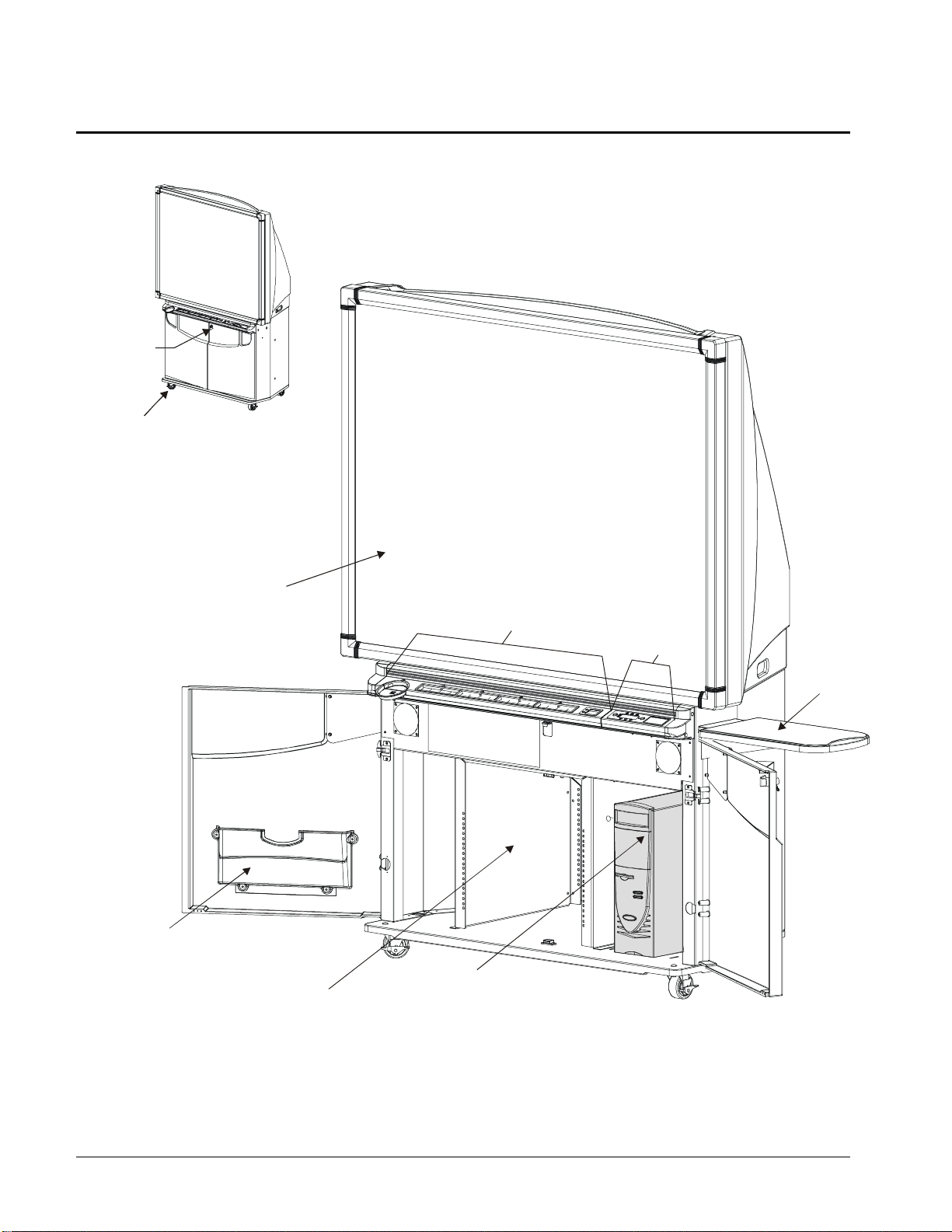
Getting to Know Your 3000i
Lockable Doors
Lockable Casters (x 4)
Manual Pocket
SMART Super Screen
SMART Pen Tray
Control Panel
Laptop Shelf
Your Comput er
Projector Platform
(with round-hole, rack-mounting rails)
2
3000i Installation Guide
Page 11
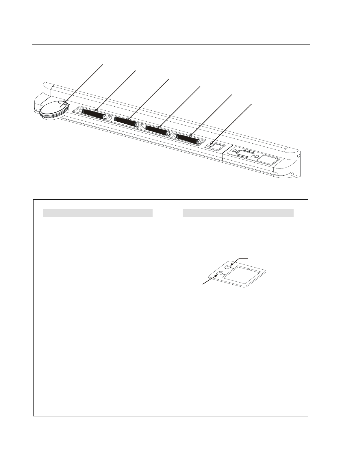
SMART Pen Tray Features
Eraser
Black Stylus
Blue Stylus
Red Stylus
Green Stylus
Pen Tray Buttons
Using a Pen Tray Stylus
To write on top of the computer image, just
pick up a stylus from the Pen Tray and
write on the interactive whiteboard.
To write in a different color, place the
current stylus back in its slot and select
another. Since color recognition comes from
the slots in the Pen Tray rather than the
styluses themselves, you must ensure that
each stylus is returned to its proper slot (the
slot with the corresponding color) when you
finish using it.
You also have the option of changing any or
all of these styluses to highlighters,
assigning one of 16 colors to them, or
altering their width. You can also change the
size of the area erased by the Pen Tray
eraser.
To reconfigure the styluses or eraser, click
on the interactive whiteboard driver icon in
the system tray, select
click on the Pen Tray tab.
Control Panel,
and
Using the Pen Tray Buttons
Press the top Pen Tray button to make the
SMART Keyboard appear for on-screen typing
and handwriting recognition. Press the bottom
button to make the next contact with the
interactive whiteboard a right-mouse click.
Keyboard Button
Right-Mouse Button
You can reconfigure these default behaviors
so that either button can initiate any of the
following events:
•
Print the current page
•
Move to the preceding or the following
Notebook file page
•
Clear all annotations from the current
page
•
Produce a floating mouse
To reconfigure the Pen Tray buttons, click on
the SMART Board icon in the system tray,
Control Panel,
select
Tray tab.
and click on the Pen
3000i Installation Guide
3
Page 12

Control Panel
The Control Panel allows you to adjust major aspects of the visual display, as well as the volume
of the internal (or a connected external) sound system. The volume settings for individual input
sources are retained. In other words, if you set the audio level differently for each device, these
settings are preserved when you switch back and forth among devices.
NOTE
busy processing a request (indicated by the appearance of an hourglass), do not press another
Control Panel button until it has completed its processing.
1 Display Source Button
2 Volume
3 Brightness
4 Contrast
: Be careful not to press the Control Panel buttons in quick succession. If the projector is
Display Source Button
1
Vol ume
2
Brightness
3
Contrast
LED Indicators of
Current Display Source
LED Indicator of
Lamp Status
4
Projector Standby Button
5
Quick Start Instructions
Control Panel Features
Press this button to select the input
display source for the projector: choose
from the internal computer, a VCR or
DVD player, or a connected guest
laptop. The LED indicators to the right of
this button indicate the current display
source. Exercise some patience when
using this button: You should expect a
very slight delay between LED
illumination and source change.
Press the arrow buttons to adjust the
volume for the current input source. Audio
settings are retained for each source.
Press the arrow buttons to brighten
or darken the projected image.
Press the arrow buttons to increase
or decrease the level of contrast in
the projected image.
LED Behavior Projector Lamp Status
Blinking moderately fast Lamp is in the process of powering up
Remains steady green Lamp is on
Blinking very fast Lamp is in reversible standby mode
Blinking slowly Lamp is in the process of powering down
No light Lamp is off
5 Projector Standby Button
Press this button to put the projector
into standby mode from its active
state. In standby mode, the projector
remains powered up, but the lamp is
off. Projector power should always
remain on, unless you will not use the
3000i for an extended period.
If the lamp is on when you press the
Projector Standby button, the
projector enters into a five-minute
period of
reversible
standby. If you
press the Projector Standby button
again during this period, the system
is instantly restored. After five
minutes, the lamp powers down and
full standby mode initiates.
The green LED indicator immediately
to the left of this button indicates the
current status of the lamp, as shown
in the table below:
4
3000i Installation Guide
Page 13
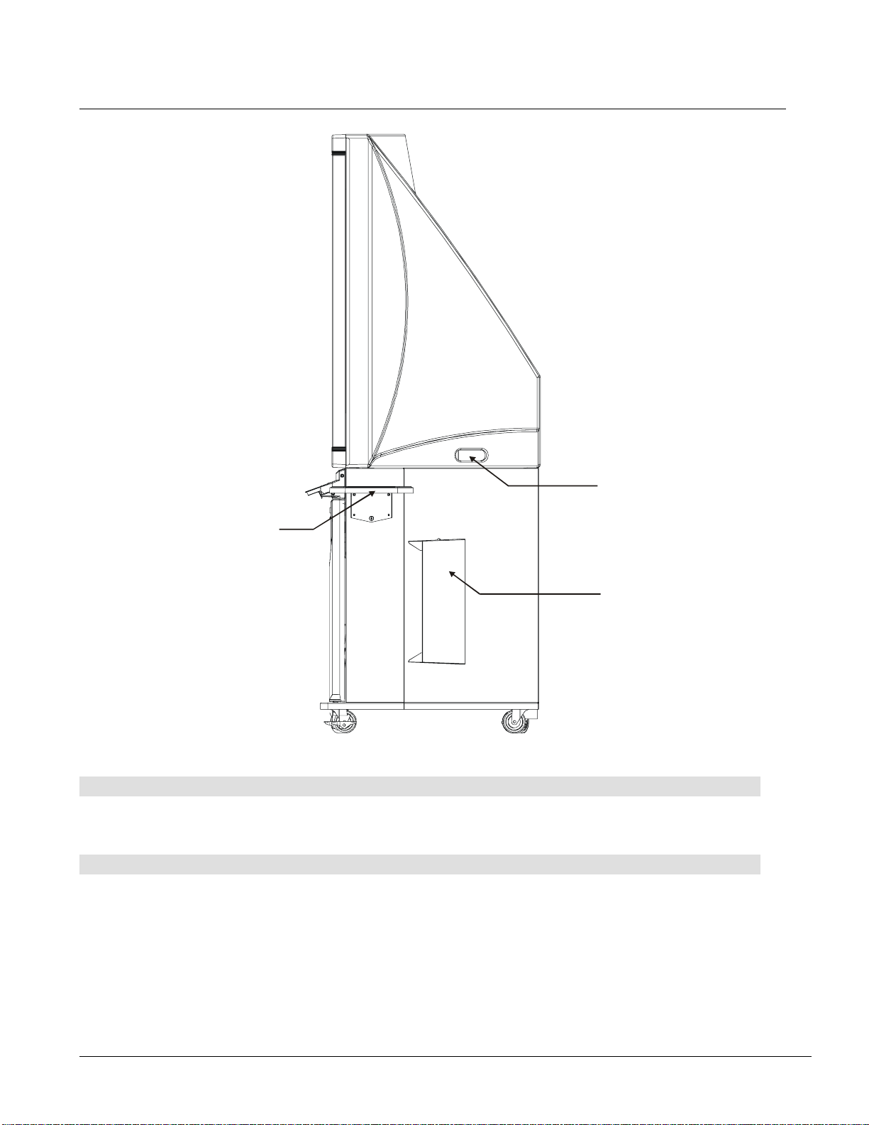
Side Features
Handle
Guest Laptop Shelf
Keyboard Holder
Guest Laptop Shelf
This shelf is specifically designed to support a guest laptop (or a VCR/DVD player). You can mount this
shelf on either side of the cabinet. For instructions on installing the shelf, see page 10.
Keyboard Holder
This holder provides a convenient means of storing the wireless keyboard when it’s not in use.
3000i Installation Guide
5
Page 14
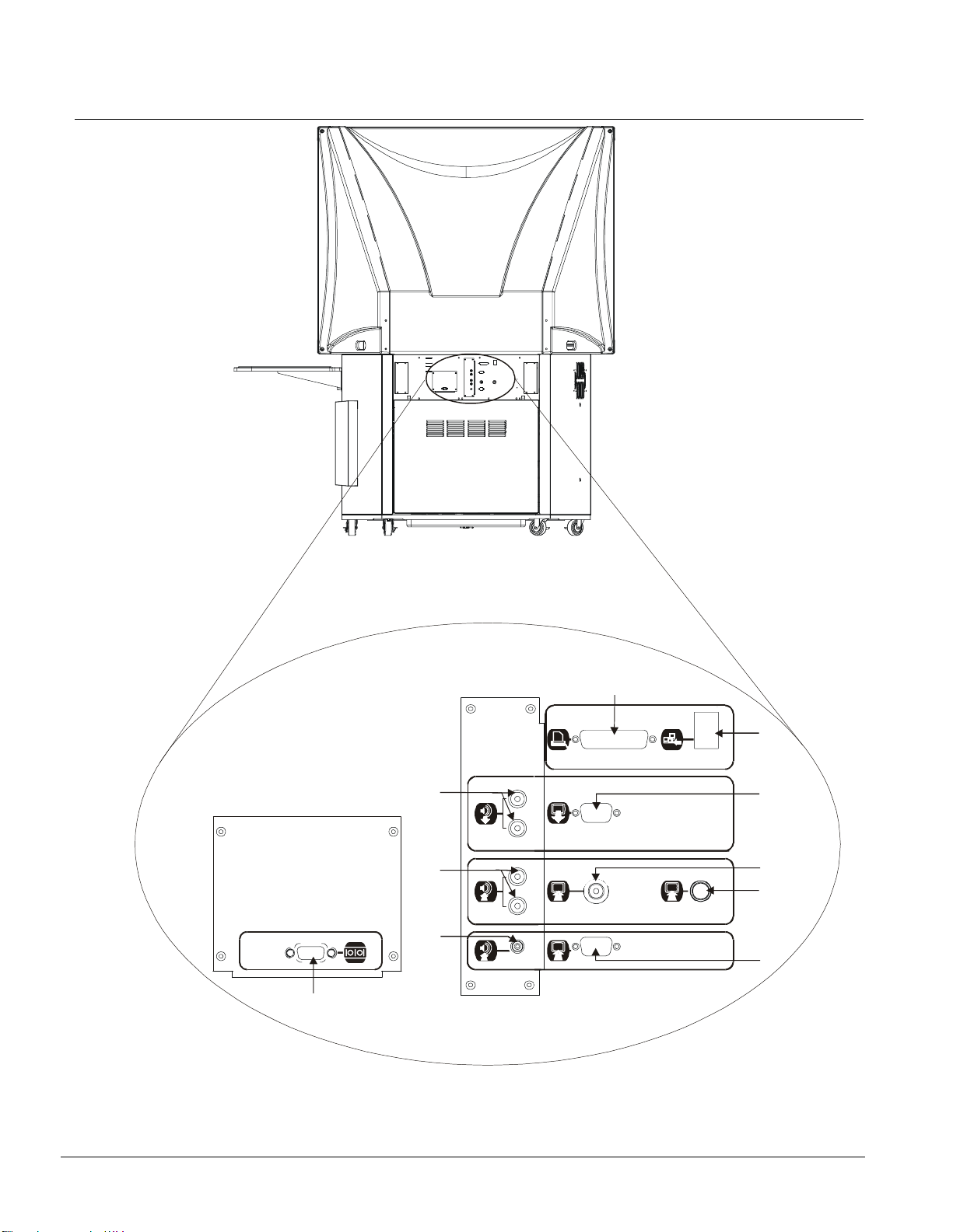
Rear Features
A
9
8
Computer 2
Computer 2
Serial
Serial
7
10
Closeup of Connection Panel
1
Printer / Network
Outputs
Auxiliary
Inputs
Computer 2 Inputs
S-Video
S-Video
2
3
4
5
6
6
3000i Installation Guide
Page 15

Connection Panel
The Connection Panel allows you to make a variety of external connections to the 3000i cabinet:
•
A printer
•
A network
•
An external projector
onto an auditorium-sized display for presentation to a large group.
•
A VCR or DVD player
VCR input (but not S-video input from a DVD player) on the interactive whiteboard. You’ll need to select
the S-video input from a VCR/DVD player via your projector remote control.
•
An external sound system
external sound system is then controlled by the Volume buttons on the Control Panel.
•
A guest laptop
laptop input on the interactive whiteboard. If the SMART Board driver is installed, you can control the
laptop by touching the board.
(1), dedicated to the internal computer
(2), making the full resources of the network available to the internal computer
(3), allowing projection of the internal computer or guest laptop (RGB output only)
(4, 5 and 8). Press the Display Source button on the Control Panel to display
(9), allowing audio rebroadcast to the room’s sound system. The
(6, 7 and 10). Press the Display Source button on the Control Panel to display the guest
Getting to Know Your Connectors
1 Printer Connector (Female)
Use a DB25 printer cable (not provided) to
connect an external printer that is
dedicated solely to the internal computer.
2 Network IN
Use a standard male-to-male RJ45
network cable (not provided) to enable
10/100 BaseT networking with the
internal computer.
3 Video OUT (Male)
Use an HD DB15 video cable (not provided)
to connect an external projector or monitor
to this video port (RGB output only).
4 RCA Composite Video IN
Use an RCA composite video cable (not
provided) to connect the video output from a
VCR/DVD player.
5 S-Video IN
Connect an S-video cable (not provided)
from the S-video OUT connector on a
VCR/DVD player.
6 Computer 2 Video IN (Female)
Connect the supplied DB15 video cable
(labeled
Umbilical cable bundle) to this 15-pin
connector (female). At the laptop end,
connect the
laptop’s own 15-pin video port.
Computer 2 Video
Computer 2 Video
in the Laptop
cable to the
7 Computer 2 Audio IN (Female)
Connect the supplied 3.5 mm audio cable
(labeled
Umbilical) to this 3.5 mm jack. At the laptop
end, connect the
to the laptop’s 3.5 mm audio OUT.
8 Audio IN
Use standard red and white RCA audio
cables (not provided) to connect the
audio output from a VCR/DVD player to
the RCA jacks. Be careful to keep your
right and left channel connections correct
for stereo sound.
9 Room Audio OUT
Use standard 3.5 mm audio cables (not
provided) to deliver unamplified sound mixed
from the internal computer, guest laptop and
VCR/DVD player to an external room sound
system. Volume buttons on the Control Panel
will control the volume of sound from the
external speakers.
10 Computer 2 Serial IN (Male)
Connect the supplied RS−232 serial cable
(labeled
Umbilical) to this 9-pin port. At the laptop
end, connect the
to the laptop’s 9-pin serial port (for a USB
connection, use the SMART USB adapter
(order number USB-ADP)).
This connection enables touch control of the
projected laptop contents on the interactive
whiteboard.
Computer 2 Audio
Computer 2 Audio
Computer 2 Serial
Computer 2 Serial
in the Laptop
in the Laptop
cable
cable
3000i Installation Guide
7
Page 16
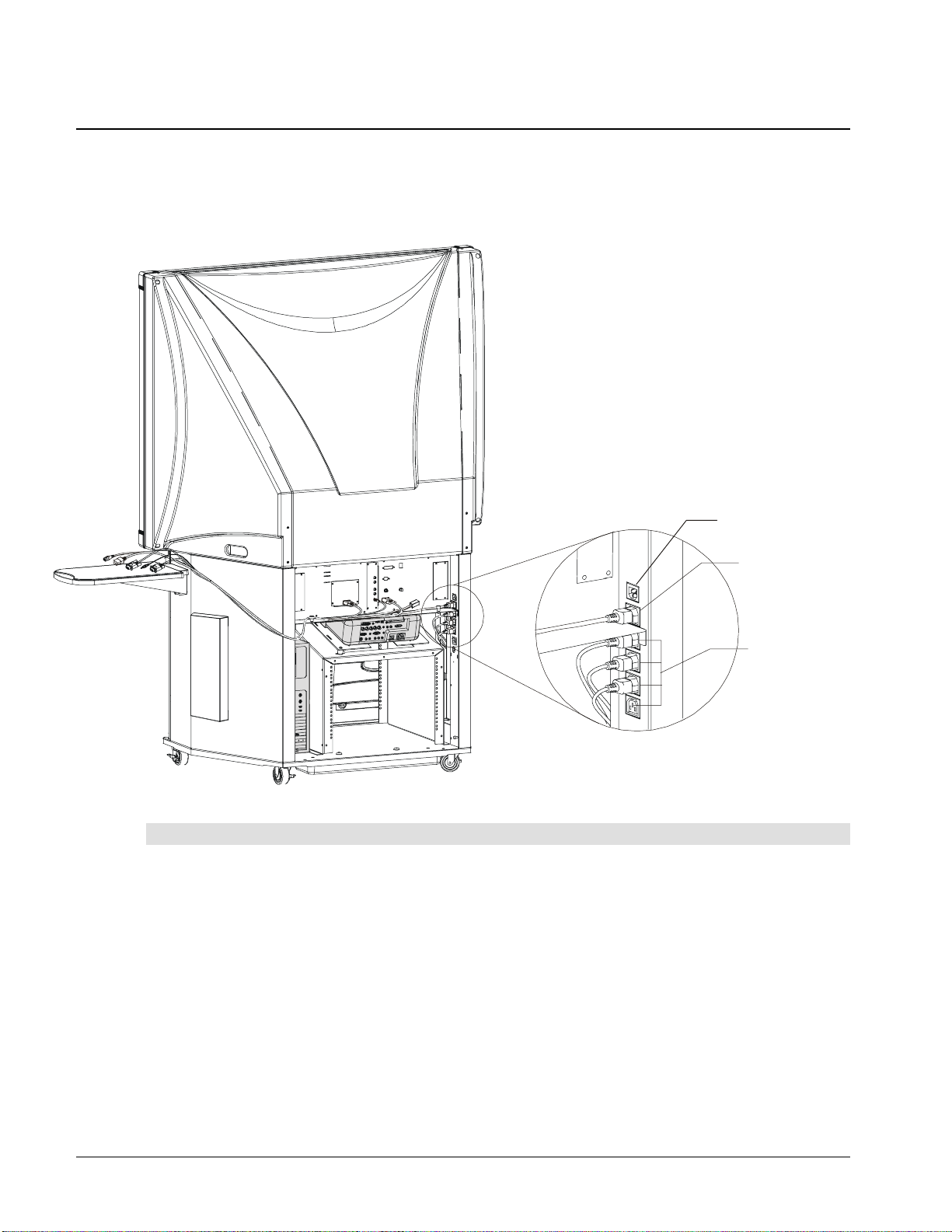
Main Power Input and Power Outputs
Located to the right of the Connection Panel (as you face the rear of the cabinet), the Main Power
IN provides power to the projector, the internal computer, connected peripherals and the laptop.
The Laptop Power OUT is used to provide power to a guest laptop via the Laptop Umbilical. The
remaining Power OUTs are for the internal computer, projector, VCR or DVD, and printer.
Main Power IN
Laptop Power OUT
Computer and
Peripherals
Power OUT (x 4)
Power Connections
Main Power IN
Connect the supplied IEC country-specific power cord to the Main Power Input and then connect the
pronged end to an appropriate wall outlet.
Laptop Power OUT
A generic laptop power cord is installed at our factory. You must connect country-specific ends (in the
power kit) to the laptop end of the umbilical.
Computer and Peripherals Power OUT (x 4)
The internal computer and connected peripherals can draw power from this series of IEC outlets, located
inside the rear access panel. The power cable for the internal computer is both supplied and connected
to one of these outlets. You connect the other end to the computer after you've installed it.
8
3000i Installation Guide
Page 17
Installation
This section of the manual describes how to:
•
set up the 3000i cabinet (p. 9)
•
install the guest laptop shelf (p. 10)
•
remove the rear access panel in preparation for computer installation (p. 11)
•
install, connect and configure the internal computer (p. 12)
•
adjusting the projected image (p.15)
•
connect a guest laptop (p. 21)
•
install and connect a VCR or DVD (p. 23)
•
connect a printer (p. 25)
•
connect a network (p. 26)
•
connect an external sound system (p. 27)
•
connect an external projector or monitor (p. 28)
Setting Up the 3000i
1
Remove the cabinet from its shipping carton (following the
2
Unpack the contents of the shipping carton and wheel the system to an appropriate
location within reach of a power source.
NOTE
: Leave sufficient space around the entire cabinet so you can comfortably access
it as you perform the following assembly and connection procedures.
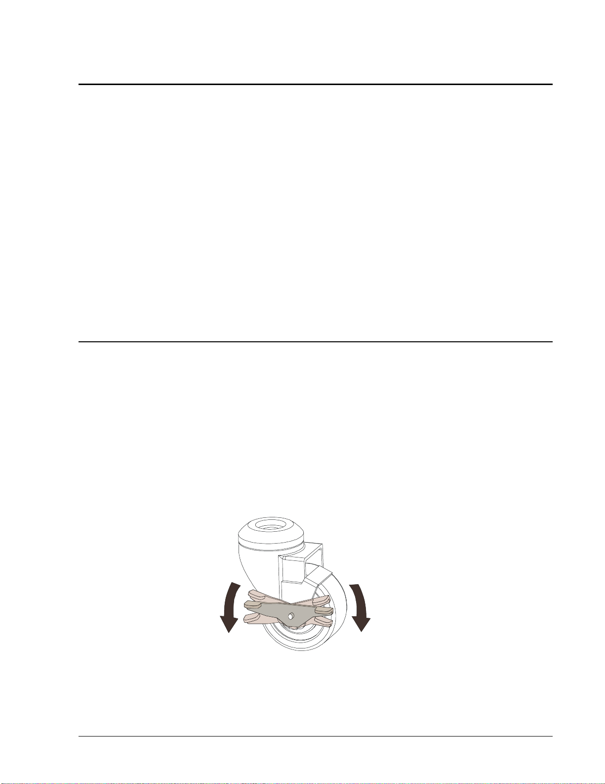
3
Lock the casters by pressing down on the caster tab locks on the wheel exterior; unlock
the casters by pressing down on the caster tab locks on the wheel interior, as shown in
the figure below.
NOTE
: As a safety precaution, and for greater ease of use, the casters should remain locked
while the 3000i is in use.
Unpacking Instructions
LockUnlock
).
Locking and Unlocking Casters
3000i Installation Guide
9
Page 18
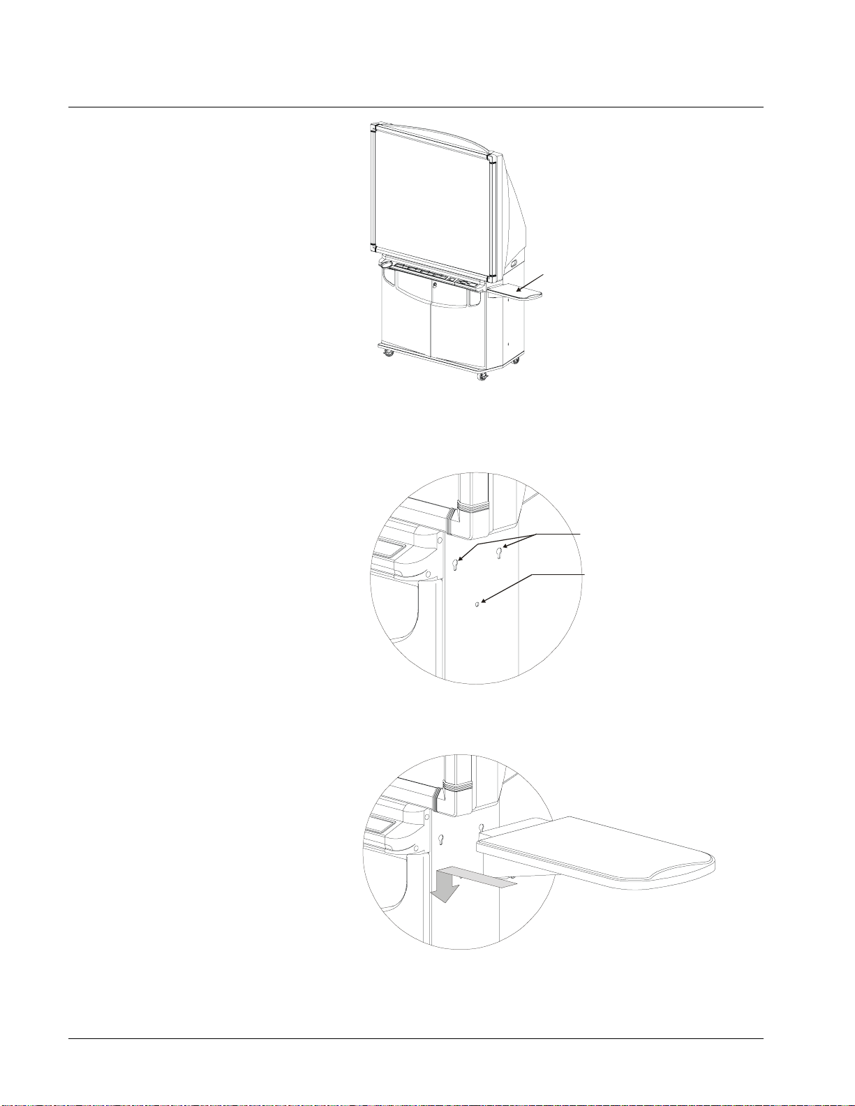
Installing the Guest Laptop Shelf
TIP
You can install the shelf
on either side of the
cabinet. If you're
installing the shelf on the
computer side of the
cabinet, install the shelf
before the computer. The
plastic hole covers are
much easier to remove
when the computer is not
inside.
1
Locate the two laptop shelf keyholes and the single thumbscrew hole on the upper right
(or left) side of the cabinet. Remove the plastic hole covers.
Guest Laptop Shelf
2 Keyholes
Thumbscrew Hole
2
Push the two protruding bolts on the edge of the shelf into the two keyholes, and then
push the shelf firmly down.
10
3
Push the captive thumbscrew at the bottom of the shelf into the thumbscrew hole and tighten.
3000i Installation Guide
Page 19
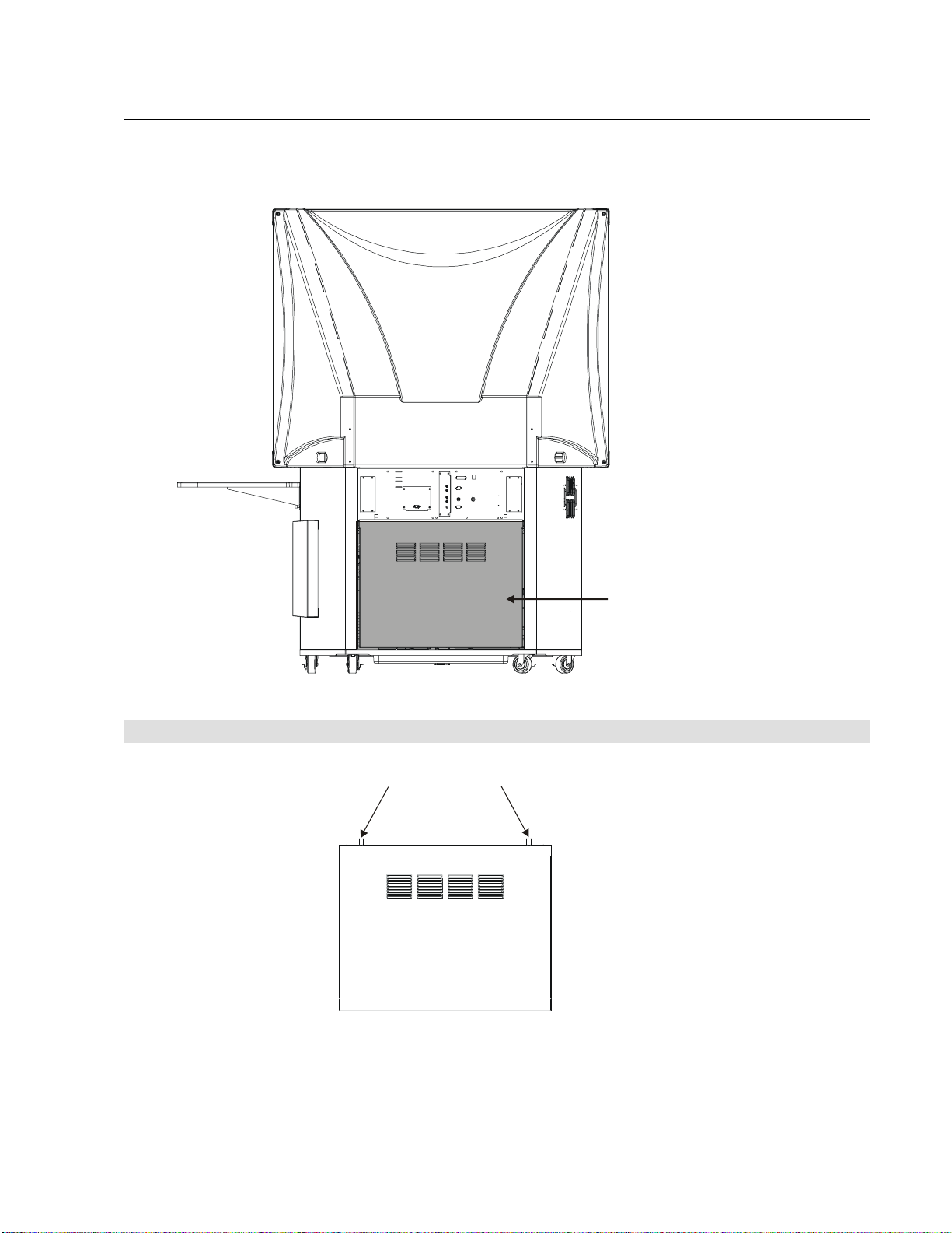
Removing the Rear Access Panel
You must remove the rear access panel before installing your internal computer. Once you’ve
powered on the projector and internal computer, it’s advisable to replace the rear access panel
as well as lock the cabinet front doors − as a security precaution.
−
Rear Access Panel
To remove the rear access panel
1
Loosen the two captive thumbscrews at the top of the rear access panel.
Captive Thumbscrews
2
Rotate the top of the rear access panel toward you and then pull it upwards, releasing it
from the cabinet.
3000i Installation Guide
11
Page 20

Installing and Connecting the Internal Computer
To position and secure the computer
1
Slide the computer into place above the computer straps, and then use them to secure
it.
NOTE
: The straps allow you to roll the cabinet from room to room without removing the
computer. However, these straps will not secure the computer in place during cabinet
transportation. If you move the cabinet, remove the computer first.
2
Locate the tie-wrapped bundle of labeled cables dangling inside the cabinet. In addition
to this cable bundle, AC power, keyboard and mouse cables are located nearby.
Network
Computer 1
Video
Computer 1
Audio
Computer 1
Serial
Printer
A
3000i Computer Cables
To make all cable connections to the computer
1
Connect the
2
Connect the
3
Connect the
NOTE
adapter (order number USB-ADP) to connect to the
4
Connect the
5
Connect the
Computer 1 Video
Computer 1 Audio
Computer 1 Serial
cable to the Monitor Video connector.
cable to the Audio Line OUT.
cable to an available COM port.
: If you're connecting a computer without a serial port, use the SMART USB
Computer 1 Serial
Printer
Network
A
cable to the 25-pin parallel port (printer) connector.
cable to the network card (if applicable).
Mouse
Keyboard
cable.
12
6
Connect the
Mouse
and
Keyboard
cables to the PS/2 mouse port (identified
by a mouse symbol) and the PS/2 keyboard port (identified by a keyboard symbol).
7
Connect the AC
power cord to the Computer Power IN port.
3000i Installation Guide
Page 21

Powering up the 3000i
1
Locate the AC power cord in the power kit.
2
Plug the this cord into the Main Power IN, located to the right of the Connection Panel.
Main Power IN
Location of Main Power Inlet
3
Plug the other end of the power cord into a wall outlet.
4
Go to the front of the cabinet, open the front door, and turn on the computer's main
power switch.
5
Turn on the projector lamp by pressing the Projector Standby button on the Control
Panel (to the right of the SMART Pen Tray). The LED indicator beside this button should
blink rapidly for thirty seconds, and then remain steadily illuminated when the projector
lamp is powered up.
OR
Use the Lamp On/Off button on the projector remote control or on the Control Panel on
top of the projector to turn on the projector lamp.
After a brief, 30-second lamp pre-heat period, the 3000i screen will display an image.
6
You should now adjust the computer settings and image alignment, install the SMART
Board software CD, configure the COM port, and perform a brief orientation procedure.
These procedures are described in the following pages.
3000i Installation Guide
13
Page 22

NOTE
: We recommend that you leave the computer and projector on at all times.
However, you can set the computer to save power during periods of inactivity. The
following section describes how to do this.
Adjusting Computer Power Settings
You may prefer to shut down and power off the computer inside the 3000i completely at the
end of the day. In this case, you must open the front door and power up the computer every
day.
For greater ease of use, we recommend that you keep the computer on all the time.
However, to help preserve the computer's hard drive(s), and to conserve the life of the
projector lamp (if users neglect to press the Projector Standby button on the Control Panel
at the end of their session), we would also recommend that you change the Windows
Power Management feature of the internal computer so that the monitor and hard drive(s)
automatically turn off after a specified period of inactivity. If you decide to adopt this
recommendation, you should occasionally reboot the computer to reload the operating
system.
Shutting off the monitor after a period of inactivity will also shut down the 3000i's projector
lamp − but only if it has been configured to shut down five minutes after no new input signal
is received. This has been done for you at our factory. However, if anyone changes the
projector settings, the projector settings we've configured for you may be inadvertently
toggled off. In the event the 3000i-optimized settings are lost, follow the procedure on page
48 to restore them.
If both the computer and projector are configured properly, a five-minute projector shutdown
period will follow the designated period of computer inactivity. During the shutdown period,
the interactive whiteboard screen will turn blue. If you change your mind and want to use the
system again, you can restore the computer image by simply touching the screen. At the
end of the five-minute shutdown period, the projector lamp shuts down completely and the
screen will turn black.
We further recommend that you not activate a screen saver, regardless of whether you
power the computer down daily or not. The benefit provided by the screen saver – to avoid
image burn-in either in monitors or plasma displays – has no bearing on a projected system.
NOTE
: You can't adjust the power settings on Windows NT 4.0 systems, so the computer
must be left on with full power or shut down at the end of the day and started up again.
To adjust the computer's default power settings
1
Click the
Panel
2
Double-click
3
Click the
dialog box.
The
4
Select
NOTE:
5
In the
before hard-disk shutdown.
Start
button on the Windows Task Bar, point to
.
Display
Settings
Power Management Properties
After 1 hour
This is a recommended setting. You can select any other duration you prefer.
Turn off hard disks
and click the Screen Saver tab.
button in the
in the
Energy saving features of monitor
dialog box appears.
Turn Off monitor
list, select a time for the inactivity period that must elapse
list.
Settings
and select
section of the
Control
14
3000i Installation Guide
Page 23

NOTE
: We recommend that you select a time value of
After 2 hours
. This extended
time period ensures that guest laptop presenters − or participants in lengthy meetings
characterized by large gaps in activity − do not experience an unexpected computer
shutdown.
6
Click the Apply button and then click OK.
When the period of inactivity specified in step 4 is reached, the RGB input signal from
the computer ceases. If no other source is active, the projector itself will go into a fiveminute shutdown mode, during which time the screen will turn blue. After five minutes
have elapsed, the projector will shut down completely and the screen will turn black.
During this five-minute projector shutdown period, touching the screen (or pressing a
keyboard key) will immediately restore the input signal from the computer.
This method
of quickly restoring the computer's video signal is especially handy when you're a
passive participant in a lengthy data conference.
Adjusting the Projected Image
You may need to make a few final adjustments to the projector to ensure a focused image
that fits on the interactive whiteboard screen. While making these adjustments, check both
the reflection in the small mirror and the actual image on the screen. For an optimal image,
the reflection must be in the center of the small mirror and each side must be symmetrical.
To adjust roll
Using the wrench provided in the Accessory Kit, loosen the Locking Screw below the projector.
Tighten and loosen the large, round knob beside the Locking Screw until the image is correctly
rotated. Finally, tighten the Locking Screw with the wrench until it's snug against the projector
plate, and then give the screw a gentle quarter-turn.
Roll Adj ustment
Locking Screw (loosen before
and tighten after adjusting roll)
Turn to roll image
WARNING
: If you tighten the security screw too much, you run the risk of distorting the
projector plate.
To adjust the image laterally
Loosen the two large, black T-knobs located below the projector plate. Slide the projector
plate laterally, and then tighten the two T-knobs.
Image Side-to-Side Adjustment
Loosen to move plate side-to-side
3000i Installation Guide
15
Page 24

Image-Size Adjustment
To change the image size
To enlarge or shrink the image, loosen the three front-to-back adjustment screws and then
slide the projector backward or forward inside the slots. Once your image is a good size,
tighten the three front-to-back adjustment screws.
Loosen and then slide the
projector backward and
forward inside the three slots
NOTE
: Remember to tighten the three front-to-back adjustment screws when you're
finished.
To move the image up or down
1
Open the front doors, and locate the two thumbscrews at the side of the small mirror
assembly (see figure below).
Move Image Up or Down
Speaker Panel
(Transparent for Clarity)
Thumbscrew (x 2)
16
2
Loosen the upper thumbscrews on both sides of the small mirror.
3000i Installation Guide
Page 25

Image Down
Image Up
Loosen upper
thumbscrew (x2)
Pivot
(Do not loosen)
3
Keeping your eyes on the screen, gently push the mirror away from you to move the
image down on the screen.
OR
Pull the mirror toward you to move the image up.
4
Tighten the thumbscrews loosened in step 1.
Keeping Projector Power On
Once the projector is powered up, it should remain on. Use the Projector Standby button on the
Control Panel to power only the projector lamp on and off.
LED Indicator of Lamp Status
Projector Standby Button
When you're finished using the 3000i, or at the end of the day, press the Projector Standby
button on the Control Panel. The screen will turn black and the LED indicator will begin to blink
very quickly. You’ll have a full five minutes to change your mind and instantly restore the
system by pressing the Projector Standby button again. After five minutes, the projector will go
into full standby mode: the projector lamp will be turned off, while the projector itself remains
on.
You'll notice that the LED indicator beside the Projector Standby button will blink slowly for a short
period of time before switching off. When the projector is next required, just press the Projector
Standby button again. The LED indicator will blink quickly as the projector lamp warms up, and
then turn to steady illuminated green when the projector lamp is ready for use.
The table below correlates the behavior of the LED indicator with projector lamp status.
LED Behavior Projector Lamp Status
Blinking moderately fast Lamp is in the process of powering up
Remains steady green Lamp is on
Blinking extremely fast Lamp is in reversible standby mode
Blinking slowly Lamp is in the process of powering down
No light Lamp is off
3000i Installation Guide
17
Page 26

NOTE
: The cabinet should be unplugged if the computer and projector will not be used for an
extended period.
Matching Computer Resolution to Projector Resolution
It's very important that computer and projector resolutions match. If they don't match, the onscreen image may not properly fill the screen.
You must first ensure that the projector is set to its optimal image resolution, which is 1024 x
768 (XGA). While the projector's user manual may indicate that resolutions other than the
optimal one are permitted, you should avoid setting the projector to any other resolution than
1024 x 768. Next, ensure that the computer resolution is also set to 1024 x 768.
IMPORTANT
may not see the entire image, or the image may be too small to fill the screen, even with further
adjustments.
: If the computer resolution is set to anything other than the optimal resolution, you
To set your computer resolution to match the projector resolution (in the
Windows operating system)
NOTE
: You may need to perform the following procedure using your computer monitor, as
resolution differences can distort the image on the interactive whiteboard screen to the point
where visibility is impaired.
1
Click the Windows
Control Panel
The
2
Double-click
Display Properties
The
3
Click the
4
Under
5
Click the
6
Restart your computer, if required.
Settings
Desktop
Apply
Start
button and then select
window appears.
Display
.
dialog appears.
tab.
, adjust the pixel setting on the slider to 1024 x 768.
button and then click OK.
Settings > Control Panel
.
To set your Macintosh computer resolution to match the projector
resolution
1
Click the Apple menu.
2
3
4
Control Panels
Click
Select
The
Click the
then click OK.
Monitors
Monitors
Options
.
.
dialog box appears.
button. In the
Select a monitor setting
Installing the SMART Board Software CD
The installation process should start automatically after you insert the SMART Board
software CD into your CD-ROM drive. Otherwise, install the software as follows.
18
3000i Installation Guide
box, select 1024 x 768, and
Page 27

To install SMART Board Software for Windows operating systems
1
Insert the SMART Board software CD into your CD-ROM drive.
The SMART Board software setup program should start automatically. If it doesn't, select
Start > Run
screen instructions to install SMART Board software.
At the end of SMART Board software installation, you'll be asked if you want to put the
SMART Board icon in your Startup Folder. We recommend that you reply affirmatively.
The SMART Board tools will always be open, and your interactive whiteboard will be fully
functional without any further action whenever you start up your system.
2
Click Yes to install the SMART Board icon in the Startup folder, or click No to prevent
SMART Board software from starting whenever you start up your system.
and enter
x:\autorun.exe
(where x: is your CD-ROM drive). Follow the on-
To install SMART Board software for Macintosh computers
1
Insert the SMART Board software CD into your CD-ROM drive.
2
Double-click the
The SMART Installer window appears.
3
Click the
Continue
SMART Installer
button and then follow the instructions on your screen.
icon.
Configuring and Orienting the Interactive Whiteboard
After installing SMART Board software, you must configure and orient the interactive whiteboard.
Configuring the interactive whiteboard involves specifying which port on the internal computer is
occupied by the interactive whiteboard serial or USB connection.
If you're running SMART Board driver 6.0 (or later), the COM port configuration process is entirely
automatic. You may need to manually configure the COM port if:
•
the Windows operating system you're running does not perform plug and play (e.g.,
Windows NT 4.0 or ME)
•
the Windows operating system fails to announce that it has
You should orient the interactive whiteboard to accurately track your finger or Pen Tray tool. If the
projected image becomes misaligned, you must perform the orientation procedure again.
To select a COM port for the interactive whiteboard
1
2
Start > Programs > SMART Board Software > SMART Board Tools
Select
Click the SMART Board icon in the system tray and select
Found New Hardware
Control Panel
.
.
SMART Board Control Panel
The
3
On the Boards tab, click the
Select COM Port
The
4
If you know the COM or USB port to which the SMART Board interactive whiteboard is
connected, you can type it or select it from the COM port list. Then click the
OR
If you’re unsure of the correct COM port, click the
initiate hardware detection. Your COM ports will be searched for the presence of an
attached interactive whiteboard until the correct COM port is located.
The interactive whiteboard is now touch sensitive. Just open the SMART Board tools to
write over a projected application with a Pen Tray stylus.
dialog box appears.
appears.
Connect
button.
Detect SMART Hardware
3000i Installation Guide
Select
button to
button.
19
Page 28

To orient the interactive whiteboard
Press the SMART Board icon and select
can also access this feature by pressing the Orient button on the Boards tab of the SMART Board
Control Panel.
Orient
, and then follow the on-screen instructions. You
To orient the interactive whiteboard with extreme precision
1
Press the SMART Board icon and select
Control Panel
.
2
On the Boards tab, press the
For Mac OS X computers, the
For Mac OS 9.x or earlier, the
click the Orient button. Proceed to step 4.
For Windows operating systems, select
appears.
Edit Advanced Board Settings
The
3
Press the
4
Select the Orientation level you prefer.
5
Press the
6
Press the Orient button.
7
Press your finger squarely and firmly in the center of each red cross as it appears.
After you press on the final red cross, the orientation screen disappears.
8
Move your finger across the screen to test the orientation. The cursor should track your
finger very closely and appear directly beneath the center of your fingertip.
The 3000i is now ready for use
stylus from the Pen Tray to write in virtual, electronic ink. Capture or print the annotations
you want to save with the touch of a toolbar button. Display the contents of a guest’s laptop
computer or show a video presentation from a connected VCR or DVD player.
Pick the Orientation Precision
Apply
button, and then OK (or
Advanced
Edit Advanced Settings
Pick the Orientation Precision
.
Use your finger to open and control programs. Pick up a
button.
Board Settings
dialog box appears.
tab.
Next
for Mac OS 9.x and earlier).
dialog box appears.
dialog box appears after you
from the drop-down menu that
20
For more detailed information on basic 3000i operations, see
3000i Installation Guide
Basic Operations
on page 29.
Page 29

Connecting a Guest Laptop
It's easy to hook up the guest laptop: Simply connect it to the Laptop Umbilical. If you want
network access, you'll also need to connect the adapter end of the umbilical’s network cable
to a room network connection.
To connect a guest laptop
1
Extend the laptop end of the umbilical from the rear of the 3000i cabinet until it reaches
the laptop shelf.
Computer 2 Network
Computer 2 Network
Computer 2 Audio
Computer 2 Audio
Computer 2 Video (Male)
Computer 2 Video (Male)
Country-Specific AC Adapter (or Cable)
Country-Specific AC Adapter (or Cable)
Computer 2 Serial (Female)
Computer 2 Serial (Female)
2
Connect the country-specific power adapter (provided in the power kit) to the end of the
(Outside North Amer ica Only)
AC power cable.
3
Connect the five cables that make up the laptop end of the umbilical − the
Network, Computer 2 Audio, Computer 2 Video, Computer 2 Serial
Computer 2
AC Power
and
cables − to the appropriate connectors on the guest laptop.
NOTE
: If the guest laptop doesn't have a serial port, use the SMART USB adapter
(order number USB-ADP) to connect the
Computer 2 Serial
cable.
SMART USB Adapter
Laptop Umbilical
Connecting a Guest Laptop Via the SMART USB Adapter
3000i Installation Guide
21
Page 30

4
To enable network access, connect a standard RJ45 network cable from the network
room outlet to the umbilical’s network adapter (located at the rear of the cabinet).
RJ45 Network Cable
(from room outlet)
Umbilical Network Adapter
Umbilical Connection to Laptop Network Connection Panel
If the guest laptop is already powered up, the desktop image will appear on the 3000i
screen.
5
If the laptop is off, turn it on.
6
Press the
Display Source
button to switch to the guest-laptop video source.
The initialization screen appears on the 3000i screen.
¾¾¾¾
If the
initialization
screen does not appear on the interactive whiteboard:
Try activating the external video port on your laptop computer. Some laptop computers
can't display their internal screens and activate the external video port or external
monitor at the same time.
You may need to de-activate the internal video port on your laptop or put the internal and
external video ports into simultaneous display mode, so that the laptop displays on both
the laptop monitor and the interactive whiteboard at the same time.
With newer laptops, you can synchronize the internal and external video ports at the
software level, as follows:
•
From the
•
Select the
•
Click the
Start
menu, select
Refresh
CRT/Panel
Settings > Control Panel > Display
Monitor Refresh
(or
) tab
option to activate simultaneous monitor and external video port
display
This may not be possible with older laptop models, so you may need to switch back and
forth between the internal and external video port. If you aren’t sure which commands or
keyboard combinations are required to do this, check your owner's manual.
You can now display any data stored on the laptop or external computer.
If the image on the screen is too large or too small
¾¾¾¾
22
The projector and external computer resolution may not match. To adjust your computer
resolution to match the projector resolution, click the
Control Panel > Display
Area
to match the computer resolution to the projector’s resolution.
7
Install the SMART Board software CD on the guest laptop (see page 18 for instructions).
. Click the Settings tab, and move the sliding bar in
Start
button, and select
Settings >
Screen
After installing the software, you should perform an orientation to ensure that the cursor
tracks your finger and the Pen Tray tools accurately. To do this, press the Orient button
in the SMART Board tools and follow the on-screen instructions (or turn to page 19).
3000i Installation Guide
Page 31

Connecting a VCR or DVD Player
1
Connect the yellow RCA video connector on an RCA composite video cable (not
provided) to the Video Output jack on the VCR/DVD player. This jack may be labeled
“To Monitor.” Plug the other end of the cable into the
Connection Panel.
•
If you're using an S-video cable, connect it to the "S-video Out" connector on the
VCR/DVD. Plug the other end directly into the
(See the
2
Connect standard red and white RCA audio cables (not provided) from the RCA Audio
Outputs on the VCR/DVD player to the two
NOTE
in step 4.)
Audio IN (L/R)
Panel. Keep your right and left channel connections correct for stereo sound.
NOTE
: You can’t connect audio from both a VCR and a DVD player. The Connection
Panel can only accommodate one external audio source at a time.
3
Connect the VCR/DVD player power cable to the bottom of the power bar (as shown in
the figure on the following page).
RCA Composite Video IN
S-video IN
on the Connection Panel.
jacks on the Connection
on the
4
Press the
Display Source
Video IN symbol
NOTE
: The Display Source button will
connected via S-video. To switch to an S-video source, you must use your projector
remote control. The LED indicator next to the Video IN symbol on the Control Panel will
then illuminate.
RCA Composite Video IN
(Yellow)
Audio IN (L/R)
White
Red
button on the Control Panel until the LED indicator next to the
is lit.
not
switch projector input to a VCR/DVD player
A
Printer / Network
Outputs
Auxiliary
Inputs
S-Video
Computer 2 Inputs
S-Video
S-Video IN
Connections to VCR/DVD Player
3000i Installation Guide
To S-Video Output
To Video Output
To RCA L/R Audio Outputs
23
Page 32

A Note on VCR/DVD Player Installation and Cabling
You can install the VCR/DVD player either inside or outside the cabinet (an ideal spot would
be the guest laptop shelf, if it isn’t otherwise occupied).
If you put the VCR/DVD player inside the cabinet
, place it on the cabinet floor underneath
the projector platform, but use the Connection Panel on the rear of the cabinet for all
connections. You’ll find an opening for the cables located at the top of the rear access panel
(see figure below).
If you place the VCR/DVD player on the outside of the cabinet
– for example, on an
unoccupied guest laptop shelf – you can route the video and audio cables directly to the
Connection Panel. You can route the power cable through the cable hole to the interior
power bar. Alternatively, if no laptop is connected to the laptop umbilical, you can draw
power from the AC power cord in the laptop umbilical.
For a VCR/DVD pla yer
cabinet
, route audio/video cables
through the cable hole to the
Connection Panel.
inside the
Remove plasti c cover to expose cable hole
For a VCR/DVD pla yer
cabinet
, route the power cable
through the cable hole to the
interior power bar.
outside the
Plug VCR/DVD player in here
Cable Routing for Internal and External VCR/DVD Player
24
3000i Installation Guide
Page 33

Connecting to a Printer
To connect a printer to the internal computer
Connect a standard DB25 printer cable (not provided) from the printer's parallel port to the
Printer Connector
on the Connection Panel.
DB25 Printer Cable
Printer
Printer Connector
A
Printer / Network
Outputs
Auxiliary
Inputs
S-Video
S-Video
Computer 2 Inputs
3000i Installation Guide
25
Page 34

Connecting to a Network
To connect the internal computer to a network
Connect a standard male-to-male RJ45 network cable (not provided) from the
network cable wall outlet to the
To Network Wall Outlet
Network IN
connector on the Connection Panel.
RJ45 Network Cable
Network IN
A
Printer / Network
Outputs
Auxiliary
Inputs
S-Video
S-Video
Computer 2 Inputs
26
3000i Installation Guide
Page 35

Connecting an External Sound System
To deliver unamplified sound (mixed from all sources) to an external room sound
system
Connect standard red and white RCA audio cables (not provided) from the RCA Audio Inputs
on the external sound system to the two
Keep your right and left channel connections correct for stereo sound.
To R C A Audi o I N
(L/R)
External Sound System
Audio OUT (L/R)
jacks on the Connection Panel.
A
Printer / Network
RCA Audio Cables
Audio OUT (L/R)
Red
White
Outputs
Auxiliary
Inputs
Computer 2 Inputs
S-Video
S-Video
3000i Installation Guide
27
Page 36

Connecting an External Monitor or Projector
To direct the RGB output from the internal computer or guest laptop to an
external projector or monitor
Connect an HD DB15 video cable (not provided) from the external projector or monitor to
Video OUT
the
External Projector
port in the Connection Panel. This connection is for RGB output only.
HD DB15 Video Cable
Printer / Network
Video OUT
Outputs
Auxiliary
Inputs
Computer 2 Inputs
S-Vide o
S-Video
28
3000i Installation Guide
Page 37

Basic Operations
This section describes the following 3000i operations:
•
Starting up and shutting down the 3000i
•
Putting the projector into standby mode (and restoring normal operation)
•
Adjusting the volume
•
Adjusting projector settings
•
Changing the projector display source
•
Using the interactive whiteboard
Starting Up the 3000i
The projector in an 3000i should always remain on; only the power to the projector lamp is
switched on and off at the Control Panel. For greater ease of operation, you should also
keep the computer on all the time. With the projector and computer power always on,
starting up the 3000i requires only that you restore power to the projector lamp (by pressing
the Projector Standby button on the Control Panel) and then enter your user name and
password at the logon screen.
NOTE
: To preserve the computer's hard drive(s) and the projector lamp, you may want to
put the computer hard drive and monitor into standby mode. Refer to page 14 for
instructions.
To start up the 3000i
1
If the screen is black, press the Projector Standby button on the Control Panel to power
up the projector lamp. The LED indicator beside the button should blink briefly for
approximately 30 seconds and then remain steadily illuminated when the lamp is fully
powered up.
Projector Standby Button
LED Indicator of
Lamp Status
2
If you see a logon screen, use the wireless keyboard to enter your logon ID and
password, and then press the OK button.
OR
If the screen turns from black to blue (with a SMART logo) – and no logon screen
appears – you may need to power up the computer or restore it from a standby setting.
Open the front door and turn the computer on, or press the reset button (if required).
3
To connect a laptop, refer to pages 21–22.
The table on the next page summarizes possible startup scenarios and related procedures.
3000i Installation Guide
29
Page 38

Startup Scenarios
If your 3000i is situated in a multi-user meeting room, you may find the unit in a non-operational
state when you enter the room. The table below describes what you may need to do to restore
the 3000i to a fully operational state.
What You See What You Should Do
•
Screen is black
•
Standby LED is off
•
SMART "No Source Signal" screen
•
Standby LED is steadily illuminated
The projector is in standby mode (with lamp off).
1
Press the Projector Standby button on the Control
Panel. The LED indicator will start flashing, and,
after 30 seconds, either a blue SMART "No Source
Signal" screen appears or the screen will be
restored to its pre-standby state.
If the SMART "No Source Signal" screen appears:
1
Touch the screen, press the Display Source button
or press a key on the wireless keyboard. If the
previous user logged off, the logon screen appears.
Otherwise, the screen is restored to its pre-standby
state.
2
Log on as usual (using the wireless keyboard).
The projector lamp is powered up, but the computer is
either off or in standby mode.
1
Press a key on the wireless keyboard to wake up the
computer. The login screen appears.
If the SMART "No Source Signal" screen remains:
1
Open the front doors and turn the computer on (or
press the computer reset button). The logon screen
appears.
•
Screen is black
•
LED indicator is blinking moderately
quickly
•
Screen is black
•
LED is blinking very quickly
•
No
Display Source LED is illuminated
•
Logon Screen
•
Projector Standby button has been
pressed
•
LED indicator remains off
2
Log on as usual (using the wireless keyboard).
The projector lamp is in the process of powering up. The
logon screen appears in 30 seconds.
The projector lamp is in reversible standby mode. Press
the Projector Standby button to instantly restore the
image. Or allow standby to continue for five minutes until
the LED indicator begins to blink slowly. After 30
seconds, the projector lamp will go into full standby
mode. At this point, follow the first set of instructions in
this table.
The projector lamp is still on, so you can log on as usual
(using the wireless keyboard).
Problems with the projector itself are interfering with the
normal projector lamp warm-up. Examine the projector
status LED indicator, and then consult the
troubleshooting section of the
User's Manual
.
NEC MT1065/MT1060
30
3000i Installation Guide
Page 39

Shutting Down the 3000i
Shutting down the 3000i is a simple, two-step procedure:
1
Log off.
Logging off greatly enhances system security. It also provides subsequent users with a
consistent initial interface – the system logon screen – after they've powered up the
projector lamp.
2
Press the Projector Standby button to power down the projector lamp.
Pressing the Projector Standby button preserves the life of the projector lamp and
conserves power. See
Perform this procedure at the end of a meeting or presentation and at the end of the day. If
you prefer, you can also shut down the computer.
However, we recommend logging off rather than shutting down the computer, as it simplifies
3000i use.
Turning the Projector Lamp On and Off
(below) for more details.
Turning the Projector Lamp On and Off
You should put the projector into standby mode (i.e., with the projector lamp turned off) at the
end of a meeting or the workday rather than turning it off or unplugging it. We recommend that
you keep the projector power on all the time, unless the 3000i will not be used for an extended
period. If this is the case, the cabinet itself should be unplugged.
When the projector is in its active state and you press the Projector Standby button, the
projector is first put into a
black, the projector lamp remains on so that the image can be immediately restored if
necessary.
reversible
standby mode for five minutes. W hile the screen appears
At any time during this five-minute period you can instantly restore the system by pressing the
Projector Standby button again. After five minutes, however, the projector lamp turns off and a
full standby mode initiates.
To turn the projector lamp off (end of meeting/day)
Press the Projector Standby button on the Control Panel.
The screen appears black and the LED indicator next to the button will blink very quickly for a
five-minute period to indicate a state of reversible standby. In addition, none of the source
LEDs will be lit. Pressing the Projector Standby button again during this period will instantly
restore the system.
After the five-minute reversible standby period, the LED indicator will blink slowly for
approximately 30 seconds while the lamp is powered down. When the lamp is turned off, none
of the LED indicators in the Control Panel will be lit.
NOTE
: To turn the lamp off quickly (skipping the reversible standby period), press the OFF
button on the projector remote control.
To power down the projector (if unused for an extended period)
1
Press the Projector Standby button on the Control Panel.
The LED indicator next to the Projector Standby button blinks rapidly for five minutes
(reversible standby) and slowly for approximately 30 seconds while the lamp powers
down. When the lamp is off, the LED indicator is no longer illuminated.
2
Disconnect the main 3000i power cable from the wall outlet.
3000i Installation Guide
31
Page 40

Adjusting the Volume
Volume adjustments are made for the active display source. These adjustments are made
independently of other sources, and the settings are retained when you switch input to another
source.
The default volume level is zero (no sound).
To adjust the volume
1
Press and hold the Volume
sound from the current source.
button (on the Control Panel) to increase the volume of
2
Press and hold the Volume
sound from the current source.
To restore default volume level (no sound)
Press and hold both Volume buttons simultaneously.
Adjusting the Projector Settings
Unlike the volume (described above), image brightness and contrast settings aren't retained for
individual display sources.
The default levels of brightness and contrast are both set at 50%.
To adjust the image brightness
1
Press and hold the Brightness
image.
2
Press and hold the Brightness
image.
To adjust image contrast
1
Press and hold the Contrast
contrast.
2
Press and hold the Contrast
contrast.
button (on the Control Panel) to decrease the volume of
button (on the Control Panel) to brighten the screen
button (on the Control Panel) to darken the screen
button (on the Control Panel) to increase image
button (on the Control Panel) to decrease image
32
To restore default levels of brightness or contrast
Press and hold both Contrast buttons or both Brightness buttons simultaneously.
To fine-tune the projected image
When you make initial connections, you may need to fine-tune the image, as follows:
•
Press the four up and down brightness and contrast buttons simultaneously to optimize
the image from all sources on the 3000i high-contrast screen.
•
Press the Auto Adjust button on the remote control to automatically optimize the image
in RGB mode. This will eliminate vertical banding, flickering, video noise, dot
interference and cross talk.
3000i Installation Guide
Page 41

Changing the Display Source
Press the Display Source button to change the video input source for the internal projector:
choose from the internal computer, a connected guest laptop or external computer, and a VCR
or DVD player. With every press of this button, you cycle through the input sources in the order
listed above.
Press to change the display source
LED Indicators of the
Current Display Source
This button is handy if you’re a guest laptop presenter, and you want to access programs or
network resources available from the internal computer. You don’t need to disconnect the
laptop to switch back to a display from the internal computer − just press the Display Source
button on the Control Panel.
Similarly, if you want to show a video presentation on the VCR connected to the 3000i, press
the Display Source button to switch the projector’s video input from the current video source
(e.g., the guest laptop or internal computer) to the VCR.
NOTE for S-video Use
connected by an S-video cable. You can only activate an S-video source with the projector remote
control. As soon as you activate the S-video source, the Video IN LED indicator will become
illuminated.
: You can't use the Display Source button to switch to a VCR or DVD player
Using the SMART Board Interactive Whiteboard
Once SMART Board software is installed on the internal computer, and the interactive
whiteboard is configured and oriented, you’re ready to use the 3000i. To get the most from
your interactive whiteboard, you must have both the SMART Board tools and SMART
Notebook software open and running.
SMART Board Tools
The SMART Board tools provide all the functionality beyond basic touch control and Pen Tray
button use. Specifically, the SMART Board tools provide you with annotation and toolconfiguration capabilities. It's important to note that the
to use the Pen Tray styluses and eraser
interactive whiteboard with a Pen Tray stylus, make sure the SMART Board icon appears in
the system tray (Windows operating system) or menu bar (Macintosh computer).
. In other words, if you want to write on your
SMART Board tools must be running
SMART Board
Icon
SMART Board Tools for the Windows Operating System
3000i Installation Guide
33
Page 42

SMART Board
Icon
SMART Notebook Software
Notebook software provides many object-creation tools that allow you to create a variety of
annotations within Notebook files. Notebook software commands also enable you to import
graphics, text, clip art and entire files from any other application into your Notebook file. But
Notebook software is much more than just an electronic flip chart for displaying presentations
or capturing notes in a brainstorming session. It also serves as a receptacle for anything you
write on the interactive whiteboard
over any application.
As soon as you begin writing over an application with a Pen Tray stylus, a toolbar appears
that lets you save a bitmap image of both your annotation and the underlying application with
the press of a button. Macintosh computer users can access the same annotation-capture
capability from the SMART Board tools menu. The captured image is automatically placed on
a new page of the current Notebook file.
We recommend that you put these programs into your Startup folder, either during SMART
Board software installation or later. If these programs are not in your Startup folder, you’ll
need to activate them each time the internal computer is powered up. This process is
described below.
To open SMART Board tools and SMART Notebook software
1
Navigate to
The SMART Board tools will open in the state in which they were last used. For
example, if they were last used in a minimized state, the SMART Board tools will
automatically start up as a minimized icon in the system tray.
2
Click the SMART Board icon and select
Start, Programs, SMART Board software
Notebook
.
, and then click
SMART Board
.
Definition
"Board-aware"
describes applications
that can be changed
by your actions on the
interactive whiteboard.
When you write on the
board over a projected
board-aware program,
what you write can be
saved into that
program.
3
If you plan on writing into Notebook software, leave it open and maximized on the Board.
If you want an even larger area for writing or brainstorming, select
View
menu.
Full Screen
from the
To summarize, the interactive whiteboard allows you to:
•
collaborate on electronic documents in front of a group
•
write or draw over any application with a Pen Tray stylus, and then capture an image of your
notes into Notebook software
•
create and edit a wide variety of annotation objects with either the Pen Tray pens or
Notebook software commands
•
convert your handwriting to typed text with an easy-to-use handwriting recognition
feature
•
save, print or e-mail a complete record of everything written, drawn or typed into SMART
Notebook software
Capturing What You Write
After writing over a projected non-Board-aware application, you may want to capture your
annotations. This is easily accomplished with the Save/Print toolbar that appears automatically
when you lift a Pen Tray stylus. SMART Notebook software will open automatically in the
background to receive the captured annotations.
1
Pick up a Pen Tray stylus.
The three-button Save/Print toolbar appears.
34
3000i Installation Guide
Page 43

Press to capture current screen
(including annotations) to Notebook
Press to capture an area of
your annotations into Notebook
2
Press the left button on the toolbar to save both the application window background and
Press to send annotations plus
background to a default printer
the annotations as two separate objects on a new page in Notebook software.
OR
Press the middle button to select an area of your annotations to be captured into
Notebook software.
OR
Press the right button to send the annotations plus background to the default printer.
3
Maximize SMART Notebook software to view the capture results.
3000i Installation Guide
35
Page 44

Customer Support
SMART's Technical Support team welcomes your call. However, you may want to contact your
local reseller first if you experience problems with any SMART product. SMART's resellers can
readily provide you with quick advice, so you can start enjoying the benefits of your
SMART Board interactive whiteboard without delay.
Contacting SMART Technical Support
All SMART software includes free telephone, fax and e-mail support. You may contact SMART
Technical Support at:
Telephone
Fax
: +1.403.245.0366
E-mail
: toll-free at 1.866.518.6791 (Canada /U.S.) or +1.403.228.5940 in all other countries
(Available 7 a.m. − 6 p.m. Mountain time from Monday to Friday)
: support@smarttech.com
Rear Projection
Web site
Please tell us when you purchased your 3000i, its serial number, the dealer's name, your
computer's operating system, your version of SMART Board driver, and the name of the
application software causing the problem, if applicable.
: www.smarttech.com
Other SMART Contacts
Main Switchboard
other counties
Fax (24 hr.)
E-mail:
Our Address
: +1.403.228.2500
info@smarttech.com
: SMART Technologies Inc.
Suite 600, 1177 − 11th Avenue SW
Calgary, AB CANADA T2R 1K9
Warranty
Rear Projection
All
limited equipment warranty. The integrated projector in the cabinet is covered by a two-year
limited equipment warranty. If you need to return defective merchandise, call SMART Technical
Support to receive the appropriate Return of Merchandise Authorization, as well as shipping
instructions so that your 3000i or internal projector can be sent to an authorized service center.
Warranty Shipping Charges
Shipping charges incurred from warranty service are paid as follows: The customer is
responsible for shipping the system to the service center. SMART pays return shipping via
ground service on any product returned for service within the warranty period. Any charges
associated with a customer-requested rush order are billed to the customer. Following the
warranty period, the customer is responsible for shipping the product to and from the service
center. Read the warranty shipped with your 3000i for details.
SMART Board 3000i interactive whiteboards are covered by a one-year
: toll-free at 1.888.42.SMART (Canada/U.S.) or +1.403.245.0333 in all
Registration Card
A Registration Card is shipped with every 3000i. To facilitate user support and to receive news
and updates, fill in and mail the card to SMART Technologies Inc. Alternatively, you can register
online at the end of the SMART Board software installation process.
36
3000i Installation Guide
Page 45

Appendix A: Disassembling the 3000i
Disassembling your 3000i is only necessary if you need to move the cabinet through a low
doorway, or if a cabinet component requires replacement or repair.
NOTE
: Two people are required to perform these procedures safely.
To remove the interactive whiteboard
1
Loosen the four captive fasteners on the back corners of the interactive whiteboard using a
Phillips No. 2 screwdriver. Start with the two bottom fasteners; then loosen the two at the
top (you may require a step stool to reach these fasteners).
NOTE
: Maintain constant pressure on the screwdriver to avoid damaging the screw holes.
Corner Captive
Fasteners
NOTE
: Even after the captive fasteners have been completely loosened, the interactive
whiteboard will remain suspended on two keyhole slots near the top of the cabinet.
3000i Installation Guide
37
Page 46

2
Facing the front of the cabinet, pull the bottom of the screen out slightly and disconnect
the MOD4 cable (connecting the interactive whiteboard to the Pen Tray) from the miniRJ11 socket. You'll find this cable underneath the bottom edge of the screen, in the
center.
Bezel
Socket
MOD4 Cable
3
With one person on each side, grasp the screen by the top and bottom corners. Lift the
screen up and then out to free it from the two keyhole slots that support it. Set the
screen down in a safe location.
38
WARNING:
Never touch the back of the screen. If you do smudge this surface,
lightly spray alcohol-free glass cleaner on a soft cloth and dab the affected area to
remove the marks. Never apply isopropyl alcohol, water or acetone, as these fluids
can damage the diffusion coating and permanently reduce the display quality.
3000i Installation Guide
Page 47

To remove the top half of the cabinet
1
Using the provided hex key, loosen and then remove the safety screw located inside
each side handle.
Location of Side-Handle Security Screw
Location of Side-Handle Safety Screw
Hex Key
2
With the same hex key, loosen and then remove the two safety screws located on the
underside of the top half of the cabinet, on either side of the Pen Tray and Control Panel.
Location of Underside Security Screw
Location of Underside Safety Screw
3
With each person gripping a side handle with one hand and supporting the top of the
cabinet with the other hand, carefully lift the top half of the cabinet off the bottom.
3000i Installation Guide
39
Page 48

Appendix B: Removing the Projector (to Replace the Lamp and Filter)
Replace the lamp when you see the following message: "The lamp has reached the end of its usable
life. Please replace the lamp." To do this, order a replacement standard lamp (MT60LP) or extended
life lamp (MT60LPS) from your NEC or SMART dealer. Generally, you should plan on replacing your
lamp after 2000 hours of use (normal mode).
The instructions for replacing the projector lamp and filter are on pages E-53 and E-54 of the
1065/1060 User's Manual
projector in place, there is insufficient clearance above the projector to perform these tasks.
. However, you must first remove the projector from the cabinet. With the
To remove/replace the projector
1
From the front of the cabinet, open the doors and unfasten the two projector straps.
NOTE
: For enhanced clarity, the small mirror is not shown.
NEC
40
2
Loosen (without removing) the three front-to-back adjustment screws.
Front-to-Back Adjustment Screws
NOTE
: For enhanced clarity, the projector straps are shown fastened.
3
Move to the rear of the cabinet and remove the rear access panel (see page 11 for
detailed instructions).
3000i Installation Guide
Page 49

4
Disconnect all cables from the projector.
NOTE
: The projector cables are labeled so these can connections can be easily
restored (see page 42).
5
Pull the projector straps up and over the projector (through the projector handle) to get
them out of the way.
6
Slide the projector as close to the front of the cabinet as possible (within the keyhole
slots).
7
Lift the projector up so the three adjustment screws pass through the keyhole slots.
Thumbscrew x 3
Keyhole x 3
3000i Installation Guide
41
Page 50

8
Slide the projector out through the back of the cabinet.
9
Refer to page E-53 and E-54 of the
NEC 1065/1060 User's Manual
for instructions on
replacing the projector lamp and filter.
10
Reverse the steps above to replace the projector.
NOTES
•
You may need to slide the projector forward or backward to adjust the image size
before you secure the three adjustment screws.
•
Reconnect and tighten the projector cables as shown below.
1
2
3
4
5
6
7
RGB 1 IN
S-Video IN
RGB 2 IN
Video IN
RGB OUT
AC POWER
PC CONTROL
3
1
2
4
5
7
6
RGB 1 IN
S-Video IN
Red Green Blue H
RGB 2 IN
V
RGB 2 IN - V
Video IN
Reconnecting the Projector Cables
RGB OU T
Projector
AC
PC Control
42
3000i Installation Guide
Page 51

Appendix C: Connecting 19" Rack-Mount Equipment to the Projector Platform
Use the provided clip-on nuts to secure the rack-mount equipment to the sides of the projector
platform, just below the projector itself. The projector platform can accommodate rack-mount
equipment with a width of 19"
To connect rack-mount equipment to the projector platform
1
Attach the provided clip-on nuts (located in the accessory kit) to the sides of the projector
platform (as required).
2
Connect your rack-mount equipment to the clip-on nuts using 10-32 x ½" fasteners (not
provided).
(48.3 cm).
19" rack-mount equipment
Clip-on nuts
3000i Installation Guide
43
Page 52

Appendix D: Installing the Optional Shelf for Videoconferencing Equipment
You can install the optional 3000i videoconferencing shelf on either side of the cabinet. The
mounting arm of the shelf provides a convenient hidden channel for the camera cabling.
Installed Videoconferencing
Shelf
To install the videoconferencing shelf
1
Choose the side on which you want to mount the shelf. Using the supplied hex-head
screwdriver, remove the three 1/4-20 x ½" fasteners as shown. Note that one safety screw
will be removed.
*safety screw
*WARNING
: Do not lift or move the cabinet until the safety screw is replaced in step 4.
44
3000i Installation Guide
Page 53

2
Remove the four caps and plugs from the mounting arm at the location where you want
to mount the shelf. Feed the cables for the videoconferencing camera through the large
hole, down the channel and through the lower mounting point.
NOTE
: Cables shown may not match those required by your videoconferencing camera.
3
If you're installing the mounting arm on the same side as the infrared receiver (IR),
detach the receiver and leave it temporarily dangling. Carefully slide the mounting arm
onto the side of the cabinet, ensuring that the cables remain in the channel and are not
pinched.
3000i Installation Guide
45
Page 54

4
Use the three supplied 1/4-20 x ¾" fasteners in place of the 1/4-20 x ½" fasteners
(removed in step 1) to secure the mounting arm to the cabinet. The safety screw is now
replaced.
NOTE
: Now that you've replaced the safety screw, you can safely move and lift the
cabinet.
5
Hook the shelf to the keyholes in the mounting arm, tightening the thumbscrew to secure the
shelf.
46
3000i Installation Guide
Page 55

6
Cable management along the side of the cabinet is provided by the J-hook. Clip the J-hook
onto the handle on the side of the 3000i and route the cables through that hook to the
Connection Panel at the rear of the cabinet.
7
If you detached the IR receiver in step 3, use the Velcro included in the accessory kit to
reattach it to the bottom of the mounting arm.
Installation is complete. Follow the instructions in reverse order to uninstall.
3000i Installation Guide
47
Page 56

Appendix E: Projector Settings
We've configured your projector settings for optimal performance within the 3000i cabinet. These
settings, however, can be inadvertently altered. If this occurs, and the 3000i-optimized settings are
lost, follow the procedure below to restore them.
To set or restore 3000i-optimized settings for the NEC MT1060 projector
1
Press the
top of the projector.
Menu
button in either the projector remote control or the projector controls on
2
Select
3
Make sure
4
Press the
5
Select
6
Click the
This setting orients the projected image for desktop (as opposed to ceiling) rear
projection. Next, select
selects the SMART logo to serve as the standby screen.
7
Click the
Management
NOTE
Projector Options
English
Enter
button.
Projector Options
Page 1
Page 4
: These settings are explained in the following table.
Auto Adjust
Power Management
Fan High Speed Mode
tab and select
tab and select the check boxes beside
High Speed Fan Mode
and
and then select
is selected in the
again and then select
Desktop Rear
Logo
from the
The projector automatically determines the best
resolution for the current RGB input signal, compensating
for resolution differences among input devices (such as
guest laptops).
The projector automatically shuts down when no input
signal is received from the computer (or any other source).
This helps conserve the life of your projector lamp.
The highest fan speed possible for your projector. This
keeps a projector in an enclosed space (such as a
cabinet) from overheating.
Menu
Language
Background
.
.
text box of the Menu screen.
Setup
.
from the
Orientation
scroll-down menu. This setting
Auto Adjust, Power
scroll-down menu.
48
8
Click the
RGB1
the projector starts up.
9
Click the OK button to save these settings.
Page 6
from the scroll-down menu. This makes RGB1 the default display source each time
tab, click the
Select
3000i Installation Guide
option under
Default Source Select
, and then select
Page 57

Appendix F: Laptop Umbilical Connections
The 3000i is shipped with the laptop umbilical connected to the cabinet. However, should the
umbilical become detached and require reattachment, use the following instructions.
Computer 2 Audio
Computer 2 Serial
Computer 2 Video
To connect the laptop umbilical to the 3000i cabinet
1
Connect the
(female) connector on the Connection Panel.
Computer 2 Video
cable in the Laptop Umbilical to the
Computer 2 AC Power
Computer 2 Network
Laptop Video IN
Computer 2 Serial (Female)
3000i Installation Guide
Computer 2 Network
Computer 2 Audio
Computer 2 Video (Male)
Country-Specific AC Adapter (or Cable)
49
Page 58

2
Connect the
Computer 2 Serial
cable in the laptop umbilical to the
Laptop Serial IN
(male) connector on the Connection Panel or, if the laptop doesn't have a serial port, the
SMART USB Adapter (order number USB-ADP).
3
Connect the
Computer 2 Audio
cable in the laptop umbilical to the
(female) connector on the Connection Panel.
4
Connect the
Computer 2 Network Adapter
outlet.
Computer 2
Computer 2
Serial
Serial
Connect cable
Computer 2 Serial
Umbilical Connections to Connection Panel
5
Connect the
AC power
cable from the Laptop Umbilical to the
located just below and to the right of the Connection Panel.
Laptop Audio IN
in the laptop umbilical to a room network
A
Printer / Network
Outputs
Auxiliary
Inputs
S-Video
S-Video
Computer 2 Inputs
Connect cable
Connect cable
Computer 2 Audio
Computer 2 Video
Laptop Power OUT
,
50
Plug AC Power Cable in here
Connecting the AC Power Cable from the Laptop Umbilical
3000i Installation Guide
Page 59

Appendix G: Cabling Schematic
Control Panel
Metal Pane l - may
be replaced with a
Room Control
RCA out
DCI2C
I2C
Right
Module
RCA in
Left
Channe l
SC7
Channel
PC2 in
the Connection Panel
Amp b oard to the back of
go directly from the Audio
These three connectors
PT10
RB2-67
Wireless
Keyboard
IR Receiver
These 3 cables are
bundled together.
Net
Wirele ss
Keyboard
I2C
I2C
PC1 in
PC 2 in
To S B
X-Port20/3000i
PC 1 in
PC
Projector
PC Audio
Serial
Pwr Printer
Video 1
In
Video 1
Pwr
Serial
Video
Out
Net
In
Video
Out
Video 2
IN
S-Video
IN
Printer
Comp
Video IN
Fan
Controller
Board
Fan
60-016
12V
Main In
Laptop
Projector
12v Pow er
Comp
Video
In
S-Video
Video 2
Layout is roughly the same as viewed from front of cabinet looking inside to Connection Panel
PC
Aux
Bar
Power
3000i Installation Guide
51
Page 60

Index
A
Adjusting
Computer Power Settings, 14
Projector Settings, 32
Projected Image, 15
Volume, 32
B
Basic Operations, 29
Adjusting Projector Settings, 32
Adjusting the Volume, 32
Changing the Display Source, 32
Shutting Down the 3000i, 31
Starting Up the 3000i, 29
Turning the Projector Lamp On and Off, 31
Using the SMART Board, 33
Brightness, 4
C
Cabling schematic, 51
Capturing What You Write, 34
Changing the Display Source, 32
Cleaning
Cabinet components and mirrors, ii
Projector, iii
Computer Power Settings, 14
Configuring and Orienting the SMART Board, 18
Connecting
a Guest Laptop, 21
a VCR or DVD, 23
Connection Panel, 7
Contrast, 4
Control Panel Features, 4
Customer Support, 36
D
Default Source Select, 48
Disassembling the RPSB 3000i, 37
Display Source Button, 4
G
Guest Laptop, 21
Guest Laptop Connection, 21
Guest Laptop Shelf, 5, 10
Installing, 10
I
Installing, 9
Guest Laptop, 21
Internal PC, 12
Printer, 25
Removing the Rear Access Panel, 11
SMART Board software, 18
VCR or DVD, 23
videoconferencing shelf, 44
Internal PC, 12
Connecting a, 12
Introduction, 1
K
Keyboard Holder, 5
L
Laptop internal video port, 22
Laptop Power Output, 8
Laptop Umbilical Connections, 49
M
Macintosh Computer
Installing SMART Board Software, 18
Main Power Input, 8
Matching Computer Resolution to Projector
Resolution, 17
N
Network, 26
Connecting a, 26
52
External Sound System, 27
Connecting a, 27
Fan High Speed Mode, 48
Features, 1
E
F
P
Pen Tray
Buttons, 3
Features, 3
Stylus, 3
Power Connections, 8
Power Management, 48
Powering up the RPSB 3000i, 13
Printer, 25
Connecting a, 25
Projector
3000i Installation Guide
Page 61

Adjusting the image, 15
Cleaning, iii
Lamp mode, iv
Power, iv
Removal, 40
Replacing lamp, iii
Resolution, 17
Settings, 48
Projector Bulb On/Off (Standby Mode), 4
orienting, 18
SMART Board Software, 18
SMART Notebook, 1
Standard Connection Panel, 1
Starting Up the 3000i, 29
T
Turning the Projector Lamp On and Off, 31
R
Rack-Mount Equipment, Connecting, 43
Removing
the projector, 40
the Rear Access Panel, 11
Replacing
projector lamp, 40
S
Save/Print toolbar, 34
Selecting a COM Port for the SMART Board, 19
Setting Up the RPSB 3000i, 9
Shutting Down the 3000i, 31
SMART Board
cleaning, ii
configuring, 18
maintenance, iv
U
User Registration Card, 36
Using the SMART Board, 33
V
VCR or DVD
Connecting a, 23
Volume, 4
W
Warnings and Safety Precautions, i
Warranty, 36
Warranty Shipping Charges, 36
3000i Installation Guide
53
Page 62

Suite 600, 1177 – 11th Avenue SW
Calgary, AB CANADA T2R 1K9
Support: 1.866.518.6791 (Canada/U.S.) or +1.403.228.5940 in all other countries
Support Fax: +1.403.245.0366
Main Switchboard: 1.888.42.SMART (Canada/U.S.) or +1.403.245.0333 in all other countries
Fax: +1.403.245.0366
support@smarttech.com www.smarttech.com
99-00224-03 REV A0
 Loading...