

Page 1
Installation
Guide
SMART Board 2000i
Interactive Whiteboard
TM
2000i - DVX
2000i - DVS
Page 2

Registration Benefits
In the past, we’ve made new features such as handwriting recognition,
USB support and SMART Recorder available as free software upgrades.
Register your SMART product to be notified of free upgrades like these.
Keep the following information available in case you need to contact
Technical Support:
Serial Number
Date of Purchase
Register online at: www.smarttech.com/registration
FCC Warning
This equipment has been tested and found to comply with the limits for a Class A digital device, pursuant to Part 15 of
the FCC Rules. These limits are designed to provide reasonable protection against harmful interference when the
equipment is operated in a commercial environment. This equipment generates, uses and can radiate radio frequency
energy and, if not installed and used in accordance with the manufacturer’s instructions, may cause harmful
interference to radio communications. Operation of this equipment in a residential area is likely to cause harmful
interference in which case the user will be required to correct the interference at his own expense.
Trademark Notice
SMART Board, Notebook, DViT, LinQ, X-Port and the SMART logo are trademarks of SMART Technologies Inc.
Windows is either a registered trademark or a trademark of Microsoft Corporation in the U.S. and/or other countries.
Macintosh and Mac OS are trademarks of Apple Computer, Inc., registered in the U.S. and other countries. NEC is a
trademark of NEC Corporation. All other third-party product and company names may be the trademarks of their
respective owners.
Copyright Notice
© 1992–2005 SMART Technologies Inc. All rights reserved. No part of this publication may be reproduced, transmitted,
transcribed, stored in a retrieval system or translated into any language in any form by any means without the prior
written consent of SMART Technologies Inc. Information in this manual is subject to change without notice and does not
represent a commitment on the part of SMART.
Portions of this software are copyrighted by Intel Corporation.
Portions of this software are copyrighted by ParaGraph, a business unit of Vadem.
U.S. Patent Nos. 5,448,263; 6,141,000; 6,326,954; 6,337,681; 6,741,267; 6,747,636 and 6,803,906. Canadian Patent
No. 2,058,219. Other U.S., Canadian and foreign patents pending.
NEC VT470, NEC VT670
Printed in Canada 10/2005
Page 3

SMART Technologies Inc.
1207 – 11 Avenue SW, Suite 300
Calgary, AB T3C 0M5
CANADA
Support +1.403.228.5940 or Toll Free 1.866.518.6791 (Canada/U.S.)
Support Fax +1.403.806.1256
support@smarttech.com www.smarttech.com
99-00530-03 REV A0
Page 4
Important Information
Please read this manual carefully before setting up and using the Rear Projection SMART Board™
2000i interactive whiteboard. With proper care, your 2000i will provide years of trouble-free
service.
WARNING
WARNING
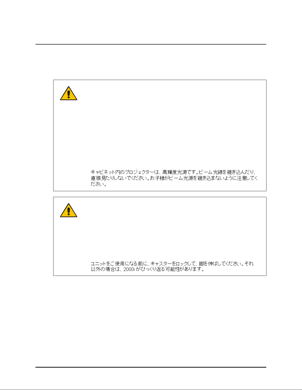
The projector inside the unit is a high brightness light source. Do not look directly
into the beam of light. Prevent children from staring directly into the beam of light.
Le projecteur qui se trouve à l’intérieur de l’armoire est une source de lumière à
luminosité élevée. Ne fixez pas et ne regardez pas dans la direction du faisceau
lumineux. Empêchez les enfants de regarder dans la direction du faisceau
lumineux.
El proyector que se encuentra en el interior de la cabina es una fuente de luz de
alta luminosidad. No mire fija ni directamente al haz de luz. Evite que los niños fijen
la vista en el haz de luz.
Der Projektor im Schrank stellt eine Lichtquelle mit hoher Intensität dar. Blicken Sie
nicht direkt in den Lichtstrahl. Verhindern Sie, dass Kinder direkt in den Lichtstrahl
blicken.
Lock the casters and extend the anti-tip feet before you use the unit. Otherwise, the
2000i could tip over.
Bloquez les roulettes et étendez les pieds avant d’utiliser l’appareil. Autrement, le
2000i risque de basculer et de tomber.
Bloquee las ruedas y extienda los pies ajustables antes de utilizar la unidad. De no
hacerlo, la pantalla 2000i podría volcarse.
Sichern Sie die Rollenbremsen und fahren Sie die Sicherheitsstützen aus, bevor
Sie das Gerät verwenden. Andernfalls könnte das 2000i umkippen.
Important Information i
Page 5
WARNING
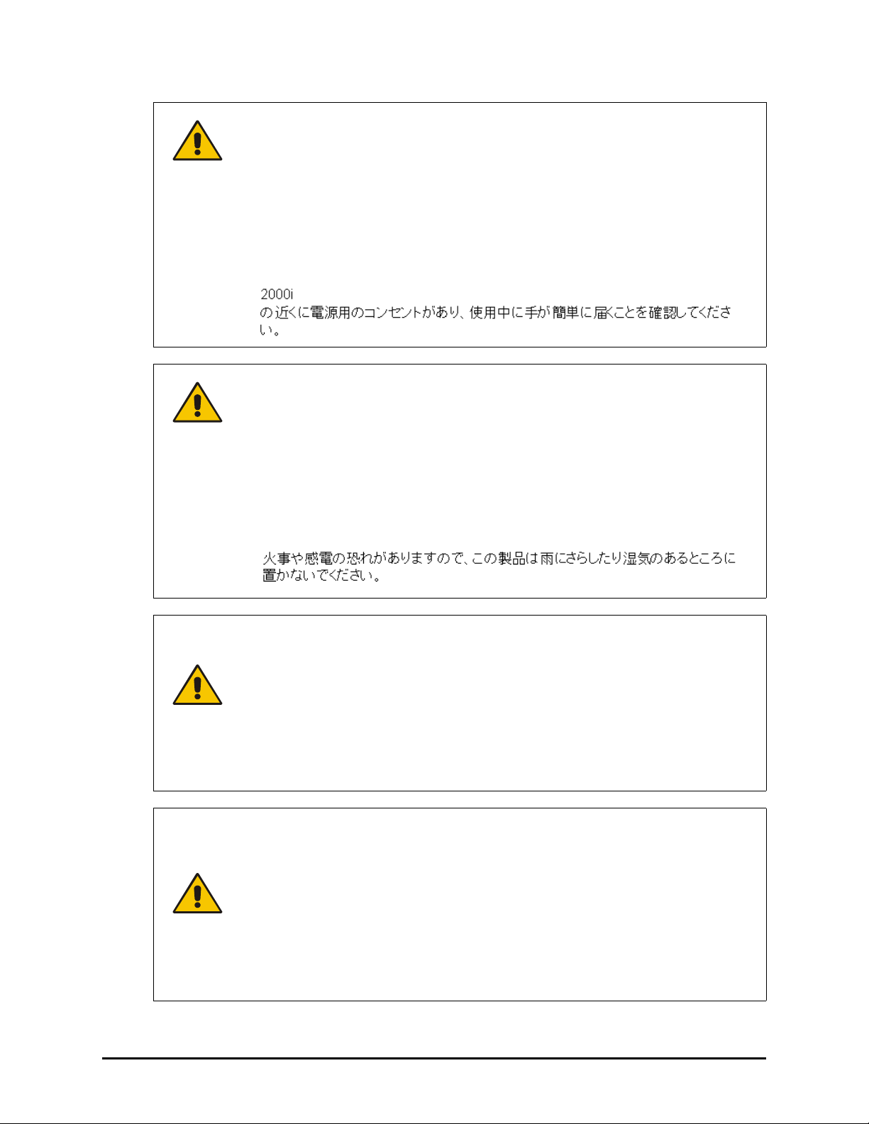
Make sure an AC socket outlet is near the 2000i and remains easily accessible
during use.
Assurez-vous qu’une prise secteur se trouve à proximité du 2000i et demeure
facilement accessible durant l’utilisation.
Asegúrese de que hay una toma de corriente alterna cerca del 2000i y que es
fácilmente accesible para su uso.
Stellen Sie sicher, dass sich in der Nähe des 2000i eine Steckdose befindet und sie
während der Verwendung auch leicht zugänglich bleibt.
WARNING
To reduce the risk of fire or electric shock, do not expose this product to rain or
moisture.
Pour réduire le risque d'incendie ou de choc électrique, évitez d'exposer ce produit
à la pluie ou à l'humidité.
Para reducir el riesgo de incendio o de descarga, no exponga este producto a la
lluvia o la humedad.
Um das Risiko eines Feuers oder eines Stromschlags zu reduzieren, darf das
Produkt weder Regen noch Nässe ausgesetzt werden.
WARNING
FOR EUROPEAN
CUSTOMERS
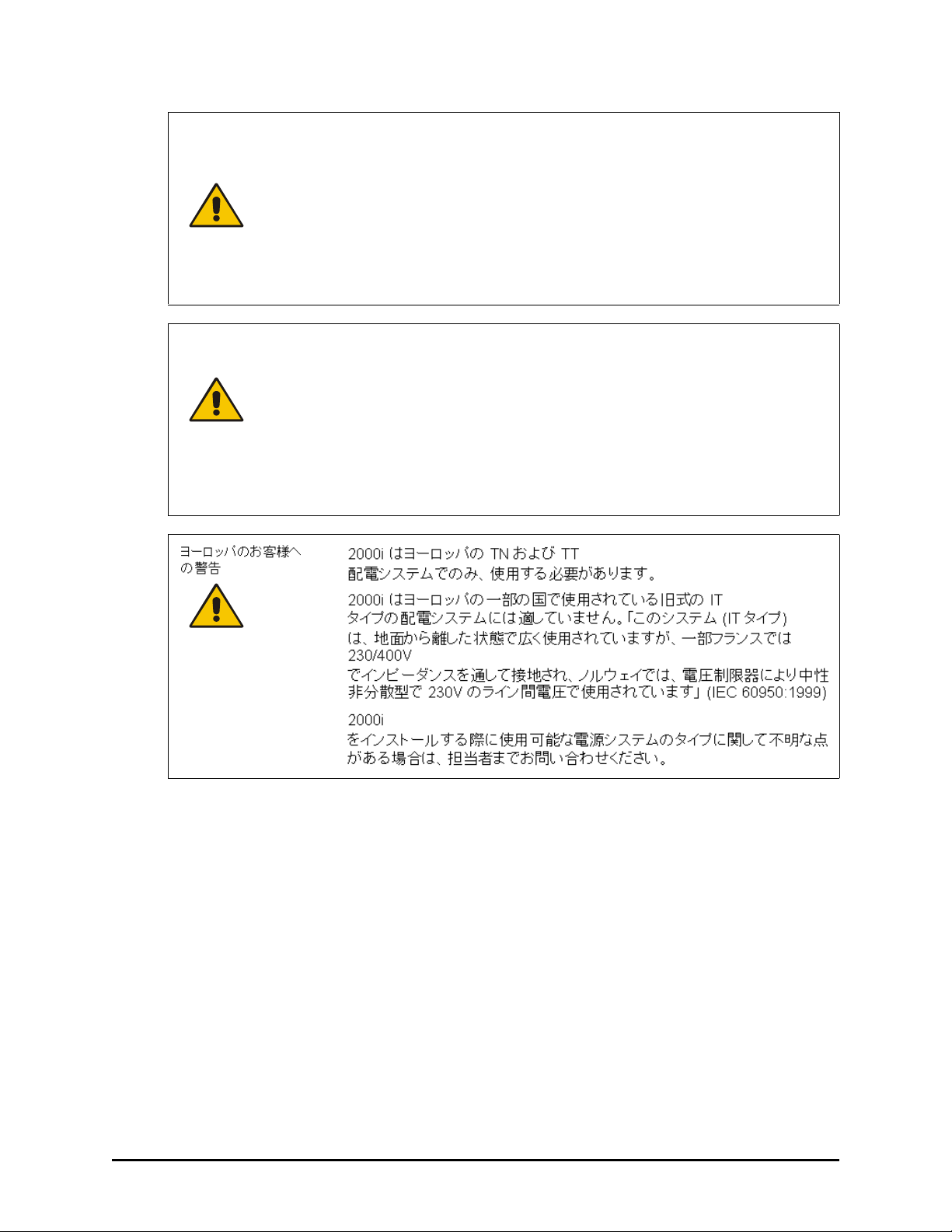
The 2000i should be used only with European TN and TT power distribution
systems.
The 2000i is not suitable for older, IT-type power distribution systems found in
some European countries. “This system (IT-type) is widely used isolated from
earth, in some installations in France, with impedance to earth, at 230/400V,
and in Norway, with voltage limiter, neutral not distributed, at 230V line-toline.” (IEC 60950:1999)
Contact qualified personnel if you're uncertain of the type of power system
available where you’re installing your 2000i.
AVERTISSEMENT
POUR LES
CLIENTS
EUROPÉENS
Le 2000i doit être utilisé uniquement avec les systèmes de distribution
d’alimentation européens TN et TT.
Le 2000i ne convient pas aux systèmes de distribution d’alimentation plus
anciens de type IP utilisés dans certains pays européens. “Ce système (type
IT) est largement utilisé isolé de la terre, dans certaines installations en
France, avec une impédance à la terre, à 230/400V, et en Norvège, avec
limiteur de tension, neutre non distribué, à 230V ligne à ligne.”(IEC
60950:1999)
Si vous avez des doutes sur le type de système d’alimentation disponible lors
de l’installation de votre 2000i, contactez un personnel qualifié.
ii Important Information
Page 6
ADVERTENCIAS
PARA LOS
CLIENTES
EUROPEOS
La 2000i sólo se podrá utilizar con los sistemas eléctricos TN y TT europeos.
Este modelo no está disponible para antiguos sistemas eléctricos de tipo IT
que aún se utilizan en algunos países europeos. “Este sistema (IT) tiene una
utilización muy extendida como núcleo aislado de tierra; en algunas
instalaciones en Francia, con impedancia de tierra, a 230/400 V; y en
Noruega, con limitador de tensión, a 230 V entre conductores.” (CEI
60950:1999)
Si no está seguro del tipo de sistema eléctrico que posee, póngase en
contacto con personal cualificado a la hora de instalar su modelo 2000i.
WARNUNG FÜR
EUROPÄISCHE
KUNDEN
Das 2000i darf nur mit europäischen TN- und TT-Netzverteilern verwendet
werden.
Das 2000i eignet sich nicht für ältere Netzverteiler vom Typ IT, die in manchen
europäischen Ländern zu finden sind. “Dieses System (IT-Typ) wird, von der
Erdung isoliert, in einigen Installationen in Frankreich mit Impedanz zu Erde
bei 230/400 V und in Norwegen mit Spannungsbegrenzer, neutral, nicht
verteilt, bei 230 V Leitung zu Leitung verwendet.” (IEC 60950:1999)
Wenden Sie sich an qualifiziertes Personal, wenn Sie sich nicht sicher sind,
welches Stromsystem dort zur Verfügung steht, wo Sie Ihr 2000i installieren.
Important Information iii
Page 7
CAUTION
The projector inside the 2000i has been designed for use under normal operating
conditions only. Normal operating conditions are defined as product use that does
not exceed 8 hours per day and 260 days per year. Exceeding these operating
conditions could cause projector damage. Damage caused by such extended use
will not be covered by the product warranty.
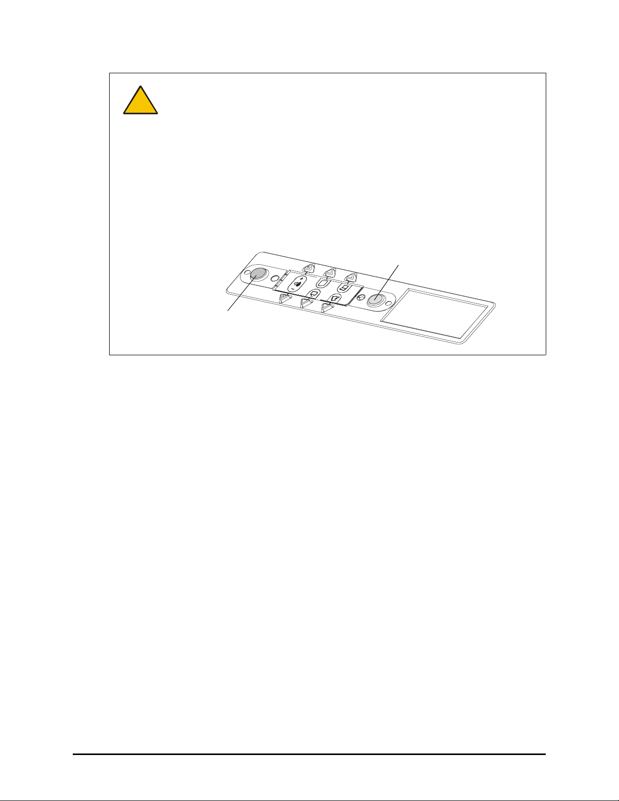
To maintain normal operating conditions, make sure the projector is in standby
mode outside of normal, daily (8 hour) operation. In standby mode, the lamp is
powered down, while the projector remains on. Be sure to press the Lamp Off
button in the Control Panel at the end of the day, and your projector will remain in
standby mode until you press the Lamp On button the next day.
NOTE: You can also configure the computer’s power management settings so that
it stops sending out a video signal after a period of idle time (page 27). This also
turns off the projector.
Lamp Off Button
(Press for Standby Mode)
Lamp On Button
(Press to Resume Operation)
Other Precautions
For operating safety and to avoid damage to the cabinet and its parts, please read the following
information carefully.
• Move the unit with care. Quick stops, excessive force and uneven surfaces can overturn the
unit.
• When you transport the 2000i, only ship it in an upright position and never lay the interactive
whiteboard face down. In addition, ensure that the projector is secure, or remove and
repackage it in the original projector’s packaging.
• If you transport the 2000i over a distance, we strongly urge you to completely repackage it
using the original packaging. This packaging was designed with optimal shock and vibration
protection. If the original packaging is no longer available, pack all components with as much
padding as reasonably possible to ensure that they are not exposed to excessive vibration or
shock.
• Clean the interactive whiteboard surface regularly so dust doesn’t build up on the surface and
adversely affect the operation of the 2000i.
• Do not touch the rear surface of the screen or apply isopropyl alcohol, water or acetone. If any
of these fluids come into contact with this surface, the diffusion coating will be damaged,
resulting in a permanent deterioration in display quality.
• If you inadvertently smudge the rear surface of the screen, dab it carefully with a soft cloth and
alcohol-free glass cleaner. Do not spray glass cleaner directly on the back of the screen; spray
it lightly on the cloth, and then gently dab the rear surface until the marks are removed.
• The 2000i uses digital cameras located inside the screen frame. Do not allow excess glass
cleaner to flow into the crack between the frame and the writing surface, because the cleaner
could damage these cameras.
iv Important Information
Page 8

• Avoid setting up and using the 2000i in an area with excessive levels of dust, humidity or
smoke.
• Lock the casters after you set up the cabinet so it remains stationary while in use.
• Avoid exposing the 2000i to extreme heat or cold. The operating temperature range is from
41°F to 84°F (5°C to 29°C) with up to 80% humidity (non-condensing). The shipping and
storage range is from 14°F to 95°F (-10°C to 35°C) with up to 80% humidity (non-condensing).
• If possible, unplug the unit before thunderstorms. However, do not touch the unit or the unit’s
power plug during a thunderstorm as there is a risk of electrical shock.
• Unplug the unit if you won’t use it for an extended period.
• Use safe practices when you’re plugging in the power cable. For example, make sure your
hands are dry and don’t insert the plug into a dusty outlet. Unplug the cabinet before you
install or service any components.
• This product has a three-wire grounding-type plug, which will only fit into an AC groundingtype power outlet. Make sure an AC socket outlet is near the 2000i and remains easily
accessible during use. If you are unable to insert the plug into the outlet, have your electrician
replace the obsolete outlet. Do not circumvent the safety features of the grounding-type plug.
Do not modify the power cord.
• Handle the power cord carefully and avoid excessive bending. Route the power cord so it’s
unlikely to be walked on or pinched by items placed upon or against it. If you must run a cable
over the floor, lay it in a flat, straight line and secure it to the floor with tape or a cable
management strip of contrasting color.
• If you require replacement parts, ensure the service technician uses replacement parts that
are specified by SMART Technologies Inc., or parts with the same characteristics as the
original.
Important Information v
Page 9

vi Important Information
Page 10

Contents
Important Information .............................................................................................................. i
Other Precautions ................................................................................................................... iv
About the 2000i ....................................................................................................................... 1
Features ................................................................................................................................... 1
Getting to Know Your 2000i .....................................................................................................2
Pen Tray Features ...................................................................................................................3
The NEC VT470 and VT670 Projectors ................................................................................... 4
Projector Settings ..................................................................................................................... 5
Adjusting Projector Focus ........................................................................................................5
Control Panel ...........................................................................................................................6
Setting Up Your 2000i ............................................................................................................. 9
Positioning the 2000i ................................................................................................................ 9
Installing a Computer ............................................................................................................. 10
Turning on the 2000i .............................................................................................................. 12
Installing the Videoconferencing/Laptop Shelf ....................................................................... 13
Connecting a Guest Laptop ................................................................................................... 14
Connecting a VCR and/or a DVD Player ...............................................................................14
Connecting an External Sound System ................................................................................. 19
Connecting an External Monitor or Projector ......................................................................... 19
Finalizing the Installation ..................................................................................................... 21
Adjusting the Projected Image ...............................................................................................21
Configuring the Computer Settings ........................................................................................ 27
Installing SMART Board Software .......................................................................................... 29
Configuring the Interactive Whiteboard .................................................................................. 29
Orienting the Interactive Whiteboard ...................................................................................... 31
Basic Operations .................................................................................................................. 33
Starting Up the 2000i ............................................................................................................. 33
Startup Scenarios ................................................................................................................... 34
Putting the 2000i into Standby Mode ..................................................................................... 35
Adjusting the Height of the Interactive Whiteboard ................................................................36
Adjusting the Volume ............................................................................................................. 37
Fine-Tuning the Projected Image ........................................................................................... 37
Changing the Display Source for the Internal Projector ......................................................... 38
Using the SMART Board Interactive Whiteboard ................................................................... 39
Enabling/Disabling Multiple Touch Mode ............................................................................... 41
Maintenance and Troubleshooting ..................................................................................... 43
Cleaning the Interactive Whiteboard and other Components ................................................ 43
Cleaning the Projector ............................................................................................................ 43
vii
Page 11

Replacing the Projector Lamp and Filter ................................................................................ 44
Lens Ring ............................................................................................................................... 48
Adjusting the Orientation Precision ........................................................................................ 48
Calibrating the Cameras ........................................................................................................49
Waste Electrical and Electronic Equipment Regulations ................................................. 51
Customer Support ................................................................................................................ 53
Contacting SMART Technical Support .................................................................................. 53
General Inquiries .................................................................................................................... 53
Returning Defective Merchandise .......................................................................................... 53
Registration ............................................................................................................................ 54
Sending Feedback ................................................................................................................. 54
Obtaining More Information on SMART Products .................................................................. 54
Index ....................................................................................................................................... 55
viii
Page 12

About the 2000i
The Rear Projection SMART Board 2000i interactive whiteboard is a height adjustable, rear
projection system with an integrated LCD projector and a 66" (167.6 cm) diagonal interactive
screen.
To enable rear projection capability, a mirror system reflects the projected image from your
computer, VCR, DVD player or guest laptop onto the back of the interactive whiteboard screen,
eliminating the distracting shadows that sometimes occur with a front projection system. You can
then perform any normal computer operation, such as opening or closing an application, scrolling
through a file, or opening your browser, just by touching the screen. If you’ve purchased the
X-Port™ 20 option, you can switch between different projector input sources (host computer, VCR,
DVD player and guest laptop) with the press of a control panel button.
SMART’s DViT™ (Digital Vision Touch) technology uses digital cameras to track objects on the
interactive whiteboard. Each camera is calibrated to recognize the position of a pen tray tool or
your finger and to send this information to the computer, which translates it to mouse clicks or
digital ink.
Features
• A touch sensitive, rear projection interactive whiteboard that enables you to do everything you
can do at a computer workstation—open files, conference with others, work on documents,
visit websites, play video clips, and more—simply by touching the screen. You can also write
over any application in digital ink using a pen tray pen or your finger, and then save these
notes to a Notebook™ file for future reference and distribution.
• An integrated 2,000 ANSI lumens, SVGA (800 × 600) NEC VT470 projector with short-throw
lens (2000i-DVS)
OR
An integrated 2,100 ANSI lumens, XGA (1024 × 768) NEC VT670 projector with short-throw
lens (2000i-DVX)
• An audio system
• A pen tray (including four pens and an eraser)
• A control panel with easily accessible projector, volume and source switching controls. The
control panel also provides button-press access to Notebook software and the Floating Tools.
• A videoconferencing/laptop shelf
• A height adjustment handle that raises and lowers the screen from 69" (175.3 cm) to 83"
(210.8 cm)
• Audio jacks at the rear of the unit let you connect the audio output from a laptop, VCR, DVD
player or room audio system
• Minimal floor space requirements. The 2000i fits easily through any standard doorway for
room-to-room mobility.
About the 2000i 1
Page 13
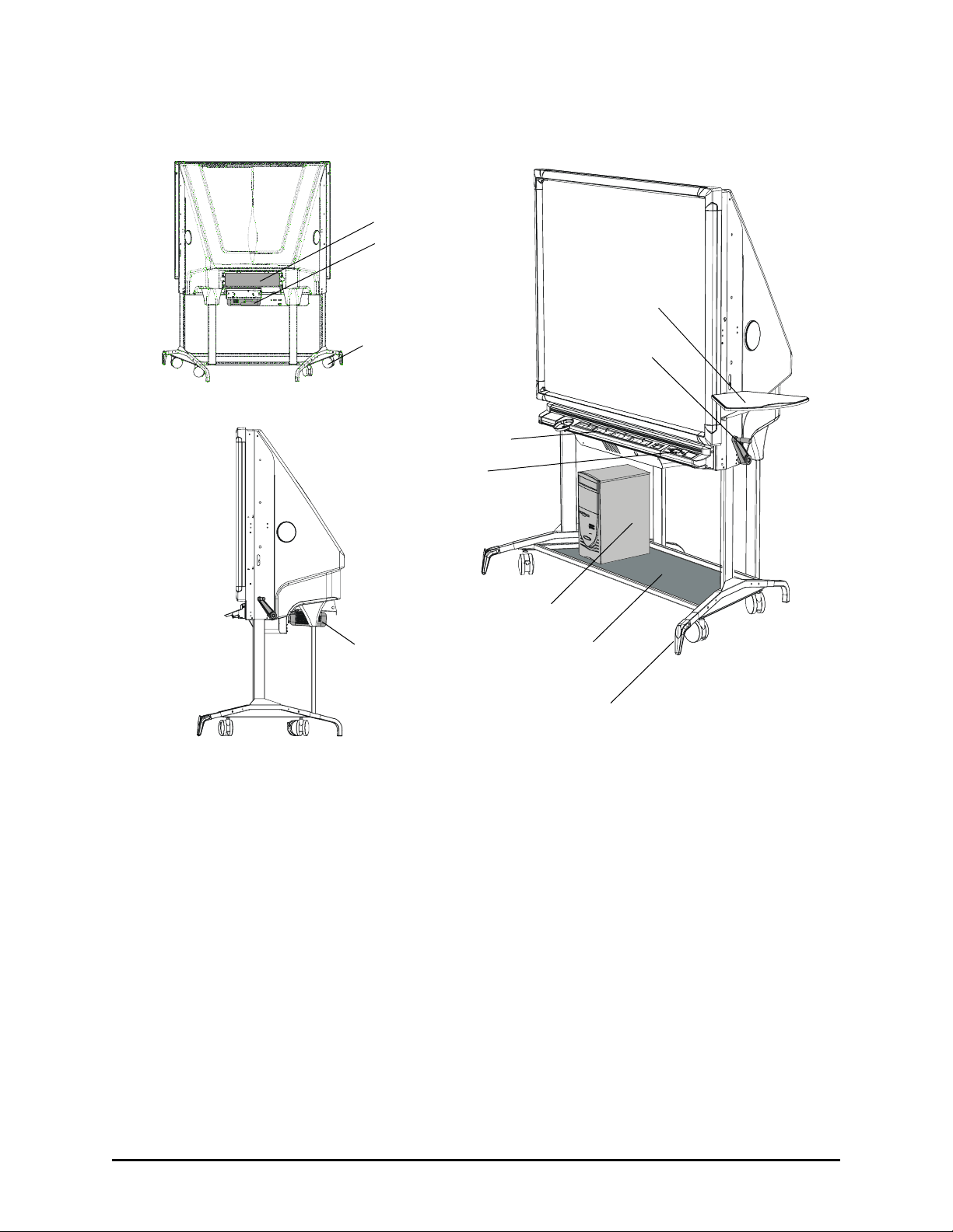
Getting to Know Your 2000i
Removable View Port
Projector
Laptop Shelf
Lockable Casters (
SMART Pen Tray
Control Panel
Your Computer
Projector
Extendable Anti-Tip Feet (
×4)
Storage Tray
Height
Adjustment
Handle
×4)
2 About the 2000i
Page 14

Pen Tray Features
Eraser
Black Pen
Blue Pen
Red Pen
Green Pen
Pen Tray Buttons
Using a Pen Tray Pen
To write over the computer image with digital ink, just pick up a pen from the pen tray and write on
the screen.
You can use SMART Board software to change any of these pens to highlighters, assign a new
color, or alter their width. You can also change the size of the area erased by the pen tray eraser.
To reconfigure the pens or eraser, press the SMART Board icon in the system tray (Windows
computers) or in the Dock (Macintosh computers), select Control Panel, and select Pen Tray
Settings.
NOTE: The provided pens have black tips because the digital cameras can more readily detect
dark objects. If you need to use a different pen, choose one with a dark tip.
Using the Pen Tray Buttons
Press the top pen tray button to make the SMART Keyboard appear for on-screen typing and
handwriting recognition. Press the bottom button to make the next contact with the interactive
whiteboard a right-click.
You can reconfigure these buttons to perform any of the following functions:
• print the current page
• move to the previous or next Notebook page
• clear all notes from the current Notebook page
• produce a floating mouse
To reconfigure the pen tray buttons, press the SMART Board icon in the system tray (Windows
computers) or in the Dock (Macintosh computers), select Control Panel, and select Pen Tray
Settings.
About the 2000i 3
Page 15
The NEC VT470 and VT670 Projectors
CAUTION
Do not move the ring that surrounds the short-throw, customized projector lenses,
even though the NEC VT470/570/670 User’s Manual states that you should use
this ring to obtain the best focus. You must disregard this information. If you move
the ring, you may cause the lenses to separate.
Instead, use the Zoom lever on the projector, which has been modified to adjust the
image focus. Again, contrary to the NEC VT470/570/670 User’s Manual, the Zoom
lever will not adjust the image size on the screen.
Two NEC projectors are featured in the 2000i line of rear projection cabinets: an NEC VT470
projector in the 2000i-DVS, and an NEC VT670 projector in the 2000i-DVX. The two projectors
have different lenses and differ in brightness and native resolution: the VT470 projector has SVGA
resolution (800 × 600) and a 2,000 lumens lamp, and the VT670 projector features XGA resolution
(1024 × 768) and a 2,100 lumens lamp. In every other respect, the two projectors are identical.
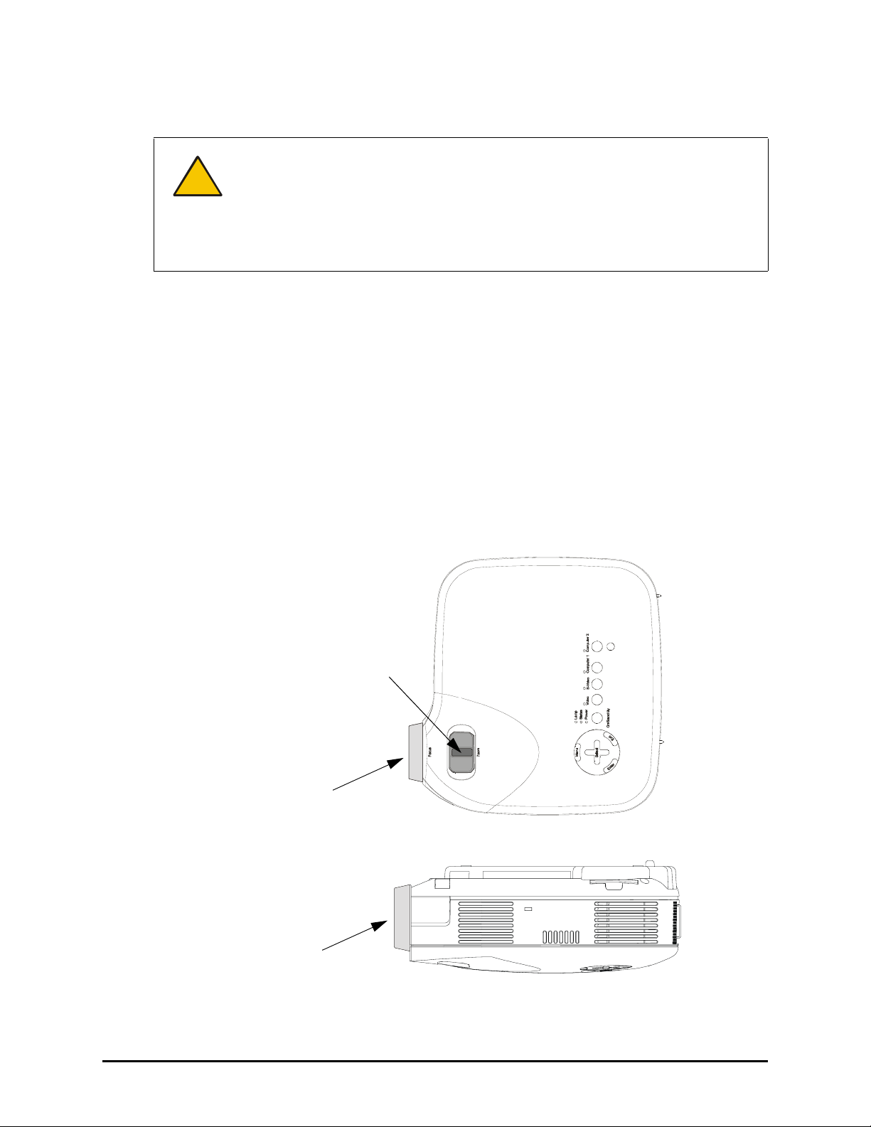
The NEC VT470/VT670 projector is secured upside-down on the projector platform. The projector
is adapted for use in the 2000i, and its behavior differs in two significant ways from the description
in the NEC VT470/570/670 User’s Manual:
• The Zoom lever does not change the size of the projected image. Instead, it adjusts image
focus.
• The ring no longer adjusts focus, and you should not move it under any circumstances.
Moving this ring may cause the lenses to separate.
Adjust focus with this lever
Do not move this ring!
Bottom View (Upside-Down)
Do not move this ring!
Side View
NOTE: See page 21 for information on adjusting the projected image.
4 About the 2000i
Page 16
Projector Settings
We’ve configured your projector settings for optimal performance with the 2000i. However, if these
settings are accidentally altered, follow the procedure below to restore them.
To set or restore the optimal settings for the NEC VT470/670 projector
1. Press the Menu button on the projector remote control or on the projector.
NOTE: The Menu button is on what is effectively the underside of the projector, which is
suspended upside down from the projector mount).
2. Select Setup > Orientation > Ceiling Rear Projection to orient the projected image for rear
projection.
3. Select Image > Auto Keystone > Off to ensure optimal image quality.
4. Select Advanced > Fan Mode > Auto.
NOTE: Although this is a default setting, it’s important enough to warrant special mention.
5. Select Advanced > Page2 > Auto Adjust > Normal to automatically determine the best
resolution for the current RGB input signal, compensating for resolution differences among
various input devices (such as guest laptops).
6. Click OK.
NOTE: All other settings are the NEC factory default settings. See pages 40–50 of the NEC
VT470/570/670 User’s Manual for a full description of all default settings.
For information on projector maintenance and instructions on replacing the projector lamp and
filter, turn to page 44.
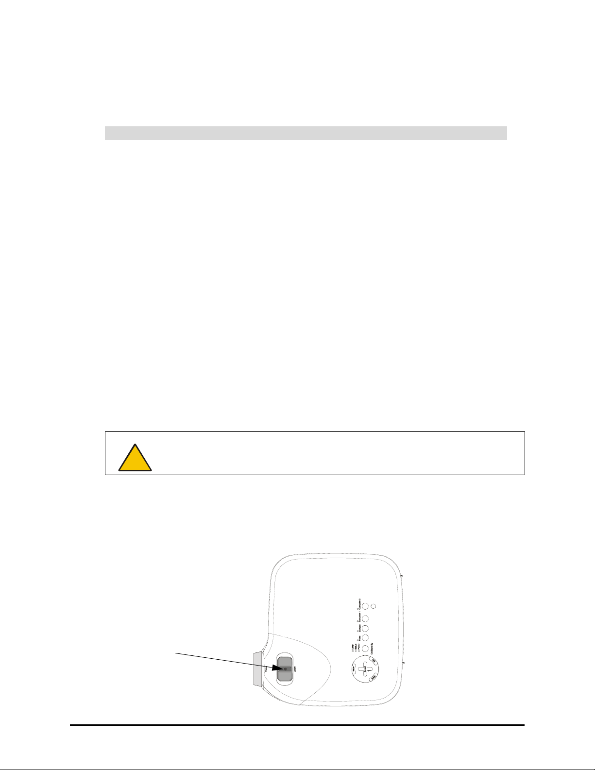
Adjusting Projector Focus
CAUTION
1. Locate the focus lever, at the bottom of the upside-down projector.
NOTE: Use this lever rather than the focus ring to adjust focus.
2. Using a 5/32" or 3/16" flat screwdriver, loosen the slot-head screw in the center of the focus
lever.
Do not move the ring that surrounds the short-throw, customized projector lens. If
you move the ring, you may cause the lenses to separate.
Loosen this screw,
adjust focus and then
tighten
About the 2000i 5
Page 17
3. Adjust the focus by moving the lever, and then tighten the slot-head screw you loosened in the
previous step.
CAUTION
Do not over-tighten the screw.
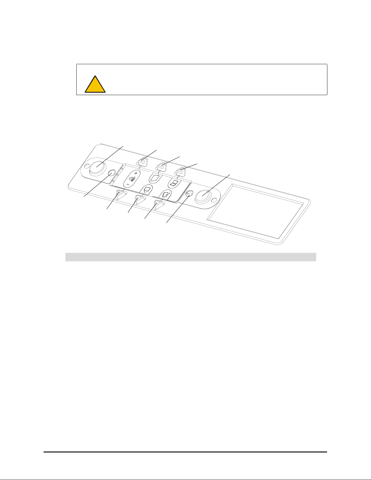
Control Panel
Use the control panel to turn the projector lamp on and off, change the display source for the
projector, open Notebook software, and adjust the volume of the internal sound system.
On LED
Volume Down
Lamp On
VCR/DVD
Player
Notebook
Software
Volume Up
Internal Computer
Guest Laptop
Lamp Off
Off LED
The Lamp On and Lamp Off Buttons
During normal operation, you should keep the projector turned on all the time. However, to
conserve the lamp, put the projector into standby mode at the end of your session (or at the end of
the day). In standby mode, the projector lamp is turned off, but the projector itself remains on.
To put the projector into standby mode, press the Lamp Off button on the control panel. For the
next three minutes, the lamp is in a reversible standby mode. The screen appears black, even
though the projector lamp remains on, allowing you to quickly restore the display by pressing any
button on the control panel.
After three minutes, the lamp cools down for 60 seconds and is then turned off.
You can skip this three-minute reversible standby period by pressing and holding the Lamp Off
button for three seconds. To turn on the projector lamp, press the Lamp On button.
6 About the 2000i
Page 18
CAUTION
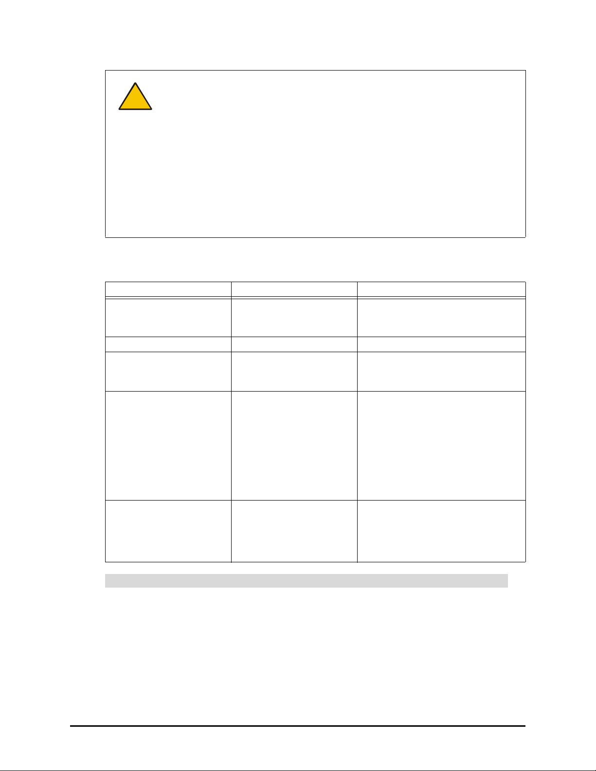
For the current status of the lamp, check the LEDs beside the Lamp On and Lamp Off buttons, and
then check the table below.
Lamp On LED Lamp Off LED Lamp Status
Flashing moderately quickly Off Lamp is turning on. During this 60-
Solid Off Lamp is turned on.
Flashing occasionally (short
flashes followed by long
pauses)
Off Flashing very quickly Lamp is in three-minute reversible
Off Flashing slowly Lamp is cooling down. This 60-
The projector inside the 2000i has been designed for use under normal operating
conditions only. Normal operating conditions are defined as product use that does
not exceed 8 hours per day and 260 days per year. Exceeding these operating
conditions could cause projector damage. Damage caused by such extended use
will not be covered by the product warranty.
To maintain normal operating conditions, make sure the projector is in standby
mode outside of normal, daily (8 hour) operation. In standby mode, the lamp is
turned on, while the projector remains on. Be sure to press the Lamp Off button in
the control panel at the end of the day, and your projector will remain in standby
mode until you press the Lamp On button the next day.
NOTE: You can also configure the computer’s power management settings so that
it stops sending out a video signal after a period of idle time (page 27). This also
turns off the projector.
second period, the Lamp On and Off
buttons are disabled.
On Lamp is off.
standby mode. In this mode, the
screen appears black but the
projector lamp remains on, allowing
you to quickly restore the display by
pressing any button on the control
panel. After three minutes, the lamp
cools down for 60 seconds before
powering off.
second cool-down follows the threeminute reversible standby period.
During this time, all control panel
buttons are disabled.
Volume Control Buttons
Press the Volume Up (+) button to increase the volume and the Volume Down (-) button to
decrease the volume.
The default volume is 0. To restore this default, press the Volume Up (+) and Volume Down (-)
buttons simultaneously.
About the 2000i 7
Page 19
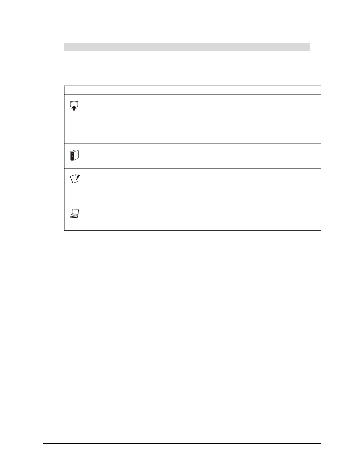
Source Buttons
Use the source buttons to switch the video and audio sources for the projector and cabinet audio
amplifier. Please note that switching sources takes a few seconds, and all buttons on the control
panel are disabled during that time.
Button Source
VCR/DVD player
If both a VCR (composite RCA connection) and a DVD player (S-video
connection) are connected to the projector, press this button to switch between
the two display sources. Note there is a three-second delay before the alternate
display source appears. If you switch to another source (such as the internal
computer) and then press this button, the last active video source is displayed.
Internal computer
Notebook software. The internal computer source must be active. For
information on using Notebook software, see page 40.
Press this button and hold it down for three seconds to open the Floating Tools.
For information on using the Floating Tools, see page 40.
Guest laptop
NOTE: You can switch to a connected guest laptop only if your system includes
the optional X-Port 20 switch option.
8 About the 2000i
Page 20
Setting Up Your 2000i
This section of the manual describes how to:
• position the 2000i (this page)
• install and connect the host computer (page 10)
• install the videoconferencing/laptop shelf (page 13)
• connect a guest laptop (page 14)
• connect a VCR or DVD player (page 14)
• connect an external sound system (page 19)
• connect an external projector or monitor (page 19)
No matter what peripherals you install, you must finalize your installation before you can use the
2000i. Read the next section of this guide (page 21) for information on finalizing your installation.
Positioning the 2000i
1. Remove the unit from its shipping carton. (To do this, follow the Unpacking Instructions.)
2. Unpack the remaining contents of the shipping carton and wheel the unit to a location that’s
within reach of a power source.
NOTE: Leave enough space around the unit to comfortably perform the following assembly
and connection procedures.
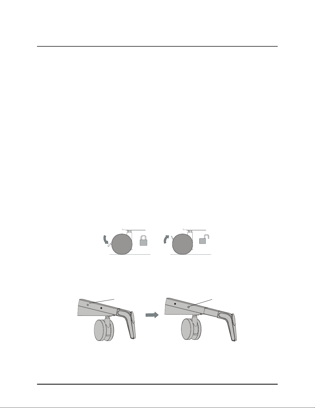
3. Lock the casters by pressing down on the caster-lock tab, as shown in the figure below.
NOTE: You can unlock the casters by pressing up on this tab.
A Locked and Unlocked Caster
4. Extend all four of the anti-tip feet. You’ll see two holes on the outer side of each leg. To extend
the feet, depress the locking ball in the inner hole, and then pull the leg out until the locking
ball engages in the outer hole.
Locking Ball in the
Inner Hole
Locking Ball in the
Outer Hole
Extending an Anti-Tip Foot
Setting Up Your 2000i 9
Page 21
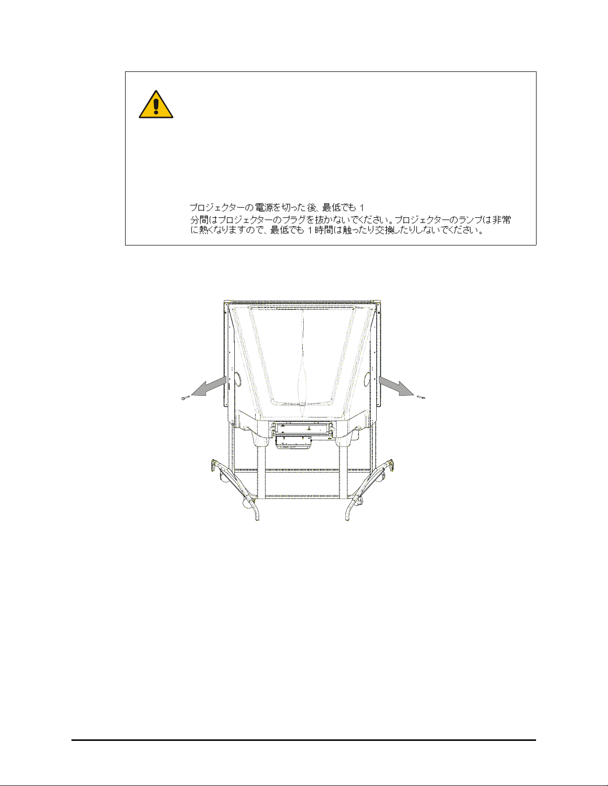
WARNING
5. Remove the bag that surrounds the projector.
6. Remove the locking pins from either side of the 2000i.
Lock the casters and extend the anti-tip feet before you use the unit.
Otherwise, the 2000i could tip over.
Bloquez les roulettes et étendez les pieds avant d’utiliser l’appareil. Autrement,
le 2000i risque de basculer et de tomber.
Bloquee las ruedas y extienda los pies ajustables antes de utilizar la unidad.
De no hacerlo, la pantalla 2000i podría volcarse.
Sichern Sie die Rollenbremsen und fahren Sie die Sicherheitsstützen aus,
bevor Sie das Gerät verwenden. Andernfalls könnte das 2000i umkippen.
Installing a Computer
When you install the internal computer, use the cable extensions that are bundled in the cabinet
along with the computer’s AC power cable.
Set your computer on the storage tray, where you’ll see straps that you can use to hold the
computer in place during normal operation or when you’re moving the 2000i from room to room.
NOTE: These straps won’t secure the computer during cabinet shipment, so if you need to
transport the 2000i, remove the computer before you ship it.
10 Setting Up Your 2000i
Page 22

The data connection for the internal computer is an RS-232 serial cable. If your computer has USB
ports, use the SMART USB adapter in the accessory box. Connect the DB9 end of this adapter to
the Computer 1 Serial cable and the USB end to your computer.
To connect a computer
1. Slide the computer into place on the bottom storage shelf, above the computer straps, and
then secure the straps around the computer.
2. Locate the bundle of labeled cables (to the right of the projector) hanging down towards the
storage tray.
Computer 1 Audio
Computer 1 Video Out (male)
2000i AC (male)
(connect to female country-specific AC Cable)
Computer 1 Serial (Female)
3. Connect the Computer 1 Video Out cable to the computer’s Monitor Video connector.
4. Connect the Computer 1 Audio cable to the computer’s Audio Line OUT connector.
5. Connect the Computer 1 Serial cable to an available serial port on the computer.
NOTE: If your computer has no available serial port, connect the SMART USB adapter
between the Computer 1 Serial cable and the computer’s USB port.
6. Connect the Mouse and Keyboard cables (not supplied) to the PS/2 mouse port and the PS/2
keyboard port on the computer.
To connect the power cables
1. Connect the Computer AC power cable to an available power outlet or power bar (not
supplied).
2. Connect the 2000i AC power cord to the country-specific AC cord in the accessory box. Then
connect this AC cord to an available power outlet or power bar (not supplied).
Setting Up Your 2000i 11
Page 23

Turning on the 2000i
1. If the projector is not on, press the main power switch on the projector.
NOTE: The projector in the figure below is shown upside down, just as it’s installed in the
2000i.
Main Power Switch
2. Turn on the computer.
3. Turn on the projector lamp by pressing the Lamp On button on the control panel (to the right of
the pen tray).
The LED indicator beside this button flashes quickly for 60 seconds, and then remains steadily
illuminated when the projector lamp has powered up.
On LED
Lamp On
Button
When an image displays, adjust the computer power settings and the image alignment on the
interactive screen. Then install SMART Board software, configure the COM port, and perform
a brief orientation procedure. All these procedures are described in Finalizing the Installation
on page 21.
NOTE: You should leave the computer and the projector on at all times (so the projector is
either in use, with the lamp illuminated, or in standby mode). However, you can set the
computer to save power during periods of inactivity (see page 27 for details).
12 Setting Up Your 2000i
Page 24

Installing the Videoconferencing/Laptop Shelf
You can position the videoconferencing/laptop shelf just above the height-adjustment handle (for
laptop use), or higher up on the frame (for use with a videoconferencing camera). You can install
the shelf on either side of the unit.
Videoconferencing
Height
Laptop
Height
To install the videoconferencing/laptop shelf
1. Remove the plastic hole covers at the location where you want to mount the shelf.
Setting Up Your 2000i 13
Page 25

2. Hook the shelf to the keyholes, and then push the shelf firmly down.
Keyholes
Captive
Thumbscrew
3. Push the captive thumbscrew at the bottom of the shelf into the thumbscrew hole and tighten.
Connecting a Guest Laptop
You can connect and control a laptop presentation by touching the interactive screen only if you:
• purchase and install the X-Port 20 switch option for the 2000i
OR
• install and run LinQ™ software
The X-Port 20 unit is an RS-232 serial switch for establishing a serial connection with the laptop,
enabling the laptop user to both write over the displayed laptop image with a pen tray pen and
control the laptop by touching the screen. In addition, it allows you to switch between the laptop,
the resident computer and a VCR/DVD player using the control panel at the front of the 2000i. If a
guest laptop requires a USB connection to the 2000i, purchase the optional USB-ADP cable from
SMART Technologies to convert USB to serial. Complete instructions for installing the X-Port 20
switch and connecting a guest laptop are in the X-Port 20 Switch Installation Guide that comes
with the X-Port 20 option kit.
LinQ software enables you to link your 2000i to a laptop on the same network. For more
information on LinQ software, see www.smarttech.com/support/product/sb/guides.asp.
Connecting a VCR and/or a DVD Player
You can connect both a VCR and DVD player to the projector, provided you use a composite video
connection for the VCR and an S-video connection for the DVD player. With each press of the
VCR/DVD Player button, the projector alternates between the two players.
Although there is only a single external audio connection, you can “daisy chain” the audio
connections: Connect the DVD player’s RCA audio cables to the VCR, and then the VCR’s RCA
audio cables to the external audio jacks at the back of the 2000i. This linked audio connection
makes the audio source switch automatically when you switch the video sources.
14 Setting Up Your 2000i
Page 26

NOTE: There is a three-second delay before the alternate display source appears. Also, when you
switch to another source (such as the internal computer), and then press the VCR/DVD Player
button, the last active video source will always appear.
You’ll need the following cables to connect a VCR or DVD player to the 2000i:
• an RCA composite video cable or an S-video cable
• standard red and white RCA stereo audio cables
To connect a VCR to the 2000i (composite video connection)
1. Turn off the projector.
2. Connect the yellow RCA video connector on an RCA composite video cable (not provided) to
the Video Output jack on the VCR/DVD player. This jack may be labeled “To Monitor”.
3. Plug the other end of the cable into the Video IN connector on the projector.
Video IN
Composite Video Cable
from VCR
NOTE: If you're using an S-video cable, connect it to the S-video OUT connector on the VCR/
DVD player, and then plug the other end directly into the S-video IN connector on the
projector. Of course, if you connect the VCR to the projector’s S-video IN connector, you won’t
be able to use an S-video cable to connect a DVD player.
Setting Up Your 2000i 15
Page 27

4. Connect standard red and white RCA stereo audio cables (not provided) from the RCA Audio
(or Audio OUT) outputs on the VCR to the two Auxiliary Audio IN jacks on the rear of the
2000i. Keep your right and left channel connections correct for stereo sound.
Computer 2
Auxiliary
Audio
Audio In
Computer 2
Auxiliary
Audio
Audio
Audio In
Out
Audio
Out
Connect red and white RCA
audio cables here
NOTE: You can’t connect the audio cables from both a VCR and a DVD player to the
Connection Panel. The panel can accommodate only one external audio source at a time.
However, you can link the DVD player and VCR audio connections as described on page 18.
5. Connect the power cable to an available outlet or power bar (not supplied).
6. Turn on the projector.
7. Press the VCR/DVD Player button on the control panel.
VCR/DVD Player Button
8. Turn on the VCR and press the Play button.
To connect a DVD player to the 2000i (S-video connection)
1. Turn off the projector.
2. Connect an S-video cable (not provided) to the S-video OUT port on the DVD player.
16 Setting Up Your 2000i
Page 28

3. Plug the other end of the cable into the S-video IN connector on the projector.
S-video IN
S-video Cable
from DVD
Player
4. Connect standard red and white RCA stereo audio cables (not provided) from the RCA Audio
(or Audio OUT) outputs on the DVD player to the two Auxiliary Audio IN jacks on the rear of
the 2000i. Keep your right and left channel connections correct for stereo sound.
Computer 2
Auxiliary
Audio
Audio In
Computer 2
Auxiliary
Audio
Audio
Audio In
Out
Audio
Out
Connect red and white RCA
audio cables here
NOTE: You can’t connect the audio cables from both the VCR and a DVD player to the
Connection Panel. The panel can accommodate only one external audio source at a time.
However, you can link the audio connections of the DVD player and VCR as described on
page 18.
5. Connect the power cable to an available outlet or power bar (not supplied).
6. Turn on the projector.
7. Press the VCR/DVD Player button on the control panel.
VCR/DVD Player Button
Setting Up Your 2000i 17
Page 29

8. Turn on the DVD player, insert a DVD and press the Play button.
To link VCR and DVD player audio connections
NOTE: Make sure there is no tape in the VCR before you proceed.
1. Connect standard red and white RCA stereo audio cables (not provided) from the RCA Audio
(or Audio OUT) outputs on the DVD player to the RCA Audio (or Audio IN) inputs on the
VCR. Keep your right and left channel connections correct for stereo sound.
To Auxiliary Audio IN
jacks on rear of
2000i
RCA Outputs
DVD Player
RCA Inputs
RCA Outputs
VCR
2. Connect standard red and white RCA stereo audio cables (not provided) from the RCA Audio
(or Audio OUT) outputs on the VCR to the two Auxiliary Audio IN jacks on the rear of the
2000i. Keep your right and left channel connections correct for stereo sound.
Computer 2
Auxiliary
Audio
Audio In
Computer 2
Auxiliary
Audio
Audio
Audio In
Out
Connect red and white RCA
audio cables here
Audio
Out
When you switch video sources, the audio source for the cabinet speakers will also switch.
18 Setting Up Your 2000i
Page 30

Connecting an External Sound System
To deliver preamplified (or line level) sound to an external room sound system
Connect standard red and white RCA audio cables (not provided) from the RCA Audio inputs on
the external sound system to the two Audio OUT jacks on the rear of the 2000i. Keep your right
and left channel connections correct for stereo sound.
Computer 2
Auxiliary
Audio
Audio In
Computer 2
Auxiliary
Audio
Audio
Audio In
Out
Connect RCA audio cables from the
external sound system here
Audio
Out
Connecting an External Monitor or Projector
To direct the RGB output from the host computer or guest laptop to an external
projector or monitor
Connect an HD DB15 video cable (not provided) from the external projector or monitor to the
Monitor OUT port on the back of the projector. This connection is for RGB output only.
Setting Up Your 2000i 19
Page 31

20 Setting Up Your 2000i
Page 32

Finalizing the Installation
With your computer and projector on, finish setting up your 2000i by:
• adjusting the projected image (this page)
• configuring the computer settings (page 27)
• installing SMART Board software on any connected computer (page 29)
• configuring the computer port (page 29)
• orienting the interactive whiteboard (page 31)
After you’ve made these adjustments and configurations, your 2000i is ready to use.
Adjusting the Projected Image
CAUTION
You may need to adjust the projector to obtain a focused image that fits on the screen. Complete
the four adjustment procedures that follow only as required. For the first three, (adjusting image
roll, adjusting the image laterally, and adjusting the image size), you must watch the image on the
back of the screen while making adjustments. You’ll also need to remove the view port cover
(attached with hook-and-loop fastener strips) to access the adjustment hardware at the rear of the
unit.
Do not adjust the ring that surrounds the short-throw, customized projector lenses,
even though the NEC VT470/570/670 User’s Manual states that you should use
this ring to obtain the best focus. You must disregard this information. If you move
the ring, you may cause the lenses to separate.
Rather, use the Zoom lever on the projector, which has been modified to adjust the
image focus. Again, contrary to the NEC VT470/570/670 User’s Manual, the Zoom
lever will not adjust the image size on the screen.
View Port Cover
For the final procedure (adjusting the image vertically), adjust the image while watching it from the
front of the unit.
Finalizing the Installation 21
Page 33

To remove the view port cover
Grasp the view port cover in the middle of each short edge, and then pull it away from the unit.
Lift from here Lift from here
You can now access the projector to perform the following image-adjustment procedures.
To adjust the image roll
1. Crouch behind the projector and look at the projected image through the view port.
22 Finalizing the Installation
Roll Adjustment
Page 34

2. While carefully observing the bottom edge of the image at the right side, use the supplied
7/16" nut driver to loosen or tighten the nut that’s located on the right side of the projector
plate, as required (see the following figure).
To adjust the image laterally
1. Crouch behind the projector and look at the projected image through the view port.
Image Side-to-Side
Adjustment
Finalizing the Installation 23
Page 35

2. Using the supplied 7/16" nut driver, loosen the two nuts located on the left side of the projector
plate.
3. Slide the projector plate to the right or left, and then tighten the two nuts.
To change the image size
1. Crouch behind the projector and look at the projected image through the view port.
Image Size Adjustment
2. Using the security key (TR20 TORX® tamper-recess key) from the accessory kit, loosen the
three TORX M4 security screws that secure the projector to the projector plate.
IMPORTANT
You’ll find these screws on top of the projector plate: one at the back of the
projector and two at the front. You’ll access the screws through one slot at the
back of the plate and two holes at the front, as shown in the two figures below.
24 Finalizing the Installation
Page 36

1
×
NOTE: To access the two screws at the front of the projector, you must reach through the view
port to the front of the projector, and maneuver the security key through the two access holes
in the projector cover (see the following figure).
NOTE: Screen removed for clarity
NOTE: As you maneuver the security key through these two access holes, watch it from the
back to see when it engages with the screws.
3. Slide the projector backward or forward to alter the image size.
4. When the image is the correct size, tighten the three screws.
Finalizing the Installation 25
Page 37

To move the image vertically
1. Move to the front of the unit and crouch down, facing the screen.
Move Image Up or Down
2. Look underneath the pen tray and locate the electronics tray. You’ll see a large access hole
covered with a plastic cap on the right side of the electronics tray.
Electronics Tray
3. Remove the plastic cap that covers the access hole. If the cap seems tight, insert the
screwdriver into the small opening at the top of the cap and carefully pry the cap off.
4. Loosen and tighten the nut inside the access hole with the supplied 7/16" nut driver to adjust
the image vertically.
CAUTION
Do not turn the nut more than two full turns in a clockwise direction. Turning the
nut too far clockwise may crush the spring that is an essential part of the
adjustment mechanism.
5. Replace the plastic cap you removed in step 3.
6. If the image requires further fine adjustment (1/4" or less), perform the procedure immediately
below.
26 Finalizing the Installation
Page 38

To further adjust the image up or down
NOTE: Perform this procedure only if the preceding procedure failed to raise or lower the image
sufficiently. This procedure will only raise or lower the image by about a 1/4" (0.6 cm).
1. Crouch behind the projector and look at the projected image through the view port.
2. Access the fine-adjustment bolt through the slot in the middle of the projector platform (shown
in the figure below).
3. Using the supplied 7/16" nut driver, turn the fine-adjustment nut to the right to raise the image,
and to the left to lower it.
NOTE: Turning this nut will only raise or lower the image by 1/4" (0.6 cm).
CAUTION
Do not remove the fine-adjustment nut. If this nut is removed, the projector
may swing down from the platform and sustain damage.
Configuring the Computer Settings
For optimal configuration, use these recommended settings for the computer inside the 2000i.
With these settings, you can balance ease of use while conserving energy and preserving the
projector’s lamp life.
For example, you can configure the power management and energy saving settings of your
computer so that it stops sending out a video signal and turns off the hard drive(s) after a period of
inactivity. Your projector then goes into standby mode if it doesn’t receive a video signal for 30
minutes. Even though the projector and the 2000i are in standby mode, you can press the Lamp
On button to quickly return both units to their normal operating states.
Finalizing the Installation 27
Page 39

Recommended Settings
You should keep the internal computer on all the time, but set it to turn off the monitor after 1 hour
of inactivity, and to put the hard disk(s) into standby mode after 2 hours. This extended period
avoids an unexpected computer shutdown during presentations, video-conferences or lengthy
meetings with gaps in computer activity.
When the computer is the 2000i’s active display source, the computer stops sending an RGB
video signal to the projector after the period of inactivity. This triggers the projector to wait for 30
minutes and then go into standby mode.
NOTE: If the input source for the projector is the video source (either composite or S-video), the
projector will not go into standby mode.
To change the settings on a Windows computer, access the Properties dialog box for your display
and adjust the energy saving features and the power management properties. For Macintosh
computers, adjust the settings in your System Preferences application. For precise instructions
on changing these settings, read the documentation that came with your operating system.
TIP
If you decide to keep your computer on all the time, you should occasionally restart
it to reload the operating system.
NOTE: You can’t adjust the power settings on Windows NT 4.0 systems, so you must leave the
computer on with full power, or shut it down at the end of the day and start it up again.
Matching the Computer Resolution to the Projector Resolution
It’s very important that the computer and projector resolutions match so the projected image
properly fills the screen. The projector resolution is either 800 × 600 (SVGA) or 1024 × 768 (XGA)
and you must ensure the computer’s resolution matches this.
NOTE: If the computer resolution is set to anything other than this optimal resolution, you may not
see the entire image, or the image may be too small to fill the screen, even with further
adjustments.
Use the information here as a guideline when you adjust your computer. For precise instructions,
read the documentation for your operating system. Also, if the image on the interactive whiteboard
is too distorted to see, use a computer monitor to adjust this setting.
To adjust the resolution setting for your Windows computer
1. Open the Windows Control Panel and press Display.
2. In the Display Properties dialog box, press the Settings tab.
3. Move the slider to a screen resolution of 800 × 600 (for a 2000i-DVS) or 1024 × 768 (for a
2000i-DVX) and then press OK.
28 Finalizing the Installation
Page 40

To adjust the resolution setting for your Macintosh computer (Mac OS X
operating system)
1. Press the System Preferences icon in the Dock.
2. Double-press Displays.
3. Select 800 × 600 (for a 2000i-DVS) or 1024 × 768 (for a 2000i-DVX) and close the dialog box.
Installing SMART Board Software
The 2000i comes with a SMART Board software CD so you can install SMART Board software on
any computer.
IMPORTANT
The SMART Board tools are open if you can see the SMART Board icon in the system tray
(Windows computers) or in the Dock (Macintosh computers).
During the installation process, you should select the option to start the SMART
Board tools automatically when you start your computer. This ensures that the
interactive whiteboard is fully functional whenever you start your computer.
To install SMART Board software
1. If you haven’t already done so, turn on the computer and the projector. To turn on the
projector, press the Lamp On button on the control panel.
NOTE: If the projector is off, press the projector’s Power button.
IMPORTANT
2. Close all open applications on the computer.
Insert the SMART Board software CD into your CD drive.
If you’re using a USB adapter and your computer can’t find the appropriate
driver for it, unplug the USB adapter from your computer, install SMART Board
software and then reconnect your USB adapter.
If the Found New Hardware wizard appears, point the wizard to the SMART
Board software CD for it to locate the correct driver.
On Windows® computers, the installation starts automatically. Follow the on-screen
instructions.
If the CD doesn’t start automatically on a Windows computer, select Start > Run and enter
x:\autorun.exe (where x: is your CD drive).
For Macintosh computers, double-click the SMART Board Install CD icon that appears on the
desktop. A Finder window will open. Double-click the SMART Board Software icon and follow
the on-screen instructions. (You may require an administrator’s password to complete the
installation.)
Configuring the Interactive Whiteboard
Normally, the internal computer’s serial or USB port is automatically detected by SMART Board
software, but you may need to manually configure the COM port if:
• the Windows operating system you’re running does not perform plug and play (for example,
the Windows NT 4.0 or Me operating system)
Finalizing the Installation 29
Page 41

• the Windows operating system fails to detect the new hardware
30 Finalizing the Installation
Page 42

To select a COM port for the interactive whiteboard
1. Click the SMART Board icon in the system tray (Windows computers) or in the Dock
(Macintosh computers), and select Control Panel.
2. Select SMART Board Settings.
The SMART Board Settings dialog box appears.
3. Click the Add SMART Board arrow and select Manually choose COM port.
The Select COM Port dialog box appears.
4. If you know which port you connected the interactive whiteboard to, select it from the list, and
click Select.
OR
If you’re unsure of the correct port, click the Detect SMART Hardware button. SMART Board
software locates the correct port for the attached interactive whiteboard.
The Ready Light in the pen tray will change to green to indicate that the interactive whiteboard
is now touch sensitive.
Orienting the Interactive Whiteboard
Before it can accurately respond to a finger or pen tray tool touch, the computer needs to know the
exact location of the projected image on the screen. You give the computer this information when
you orient the interactive whiteboard. Orienting is a very simple process of precisely touching a
grid of red crosses. With the correct orientation, the pointer appears directly beneath your finger
when you touch the interactive whiteboard.
You can also increase the orientation level for even greater touch precision.
To orient your interactive whiteboard (default 9-point orientation)
1. Press the SMART Board icon in the system tray (Windows computers) or in the Dock
(Macintosh computers), and select Orient.
The orientation screen appears.
NOTE: You can also start the orientation by pressing and holding both pen tray buttons
simultaneously.
2. Follow the on-screen instructions, pressing your finger squarely on each cross.
If required, you can redo a particular orientation point by pressing the Right-Click button or
the Left Arrow key on the keyboard. You won’t lose any previously established orientation
points. Alternatively, you can redo the entire procedure by pressing the ESC key on the
keyboard.
NOTE: If you press on the crosses out of sequence or inaccurately, a Bad Orientation Point
dialog box appears. Use the mouse to click OK, because touch awareness isn’t available.
3. When the orientation screen disappears, test the orientation by moving your finger across the
interactive whiteboard. The pointer should track your finger very closely, and appear directly
beneath the center of your fingertip.
NOTE: If the pointer doesn’t accurately track your finger, you may need to calibrate the digital
cameras (page 49).
Finalizing the Installation 31
Page 43

To orient using the Fine (20-point) or Quick (4-point) orientation levels
1. Press the SMART Board icon in the system tray (Windows computers) or in the Dock
(Macintosh computers), and select Control Panel.
2. Select SMART Board Settings.
3. Select Alignment/Orientation Precision from the list.
4. Press Quick (4 points) or Fine (20 points).
5. Press OK.
6. Perform the 4-point or 20-point orientation.
NOTE: This setting will remain in effect for all subsequent orientations until you restore the
default, 9-point orientation or otherwise change the orientation level.
32 Finalizing the Installation
Page 44

Basic Operations
This section shows you how to:
• Start up the 2000i (this page)
• Put the 2000i into standby (page 35)
• Adjust the height of the interactive whiteboard (page 36)
• Adjust the volume (page 37)
• Change the projector display source (page 38)
• Use the interactive whiteboard (page 39)
Starting Up the 2000i
You should keep the projector on at all times. However, to conserve the projector lamp, press the
Lamp Off button on the control panel at the end of your session (or at the end of the day). For
ease of operation, you should also keep the computer on all the time. By doing this, you can start
up the 2000i by restoring power to the projector lamp (by pressing the Lamp On button on the
control panel) and then entering your user name and password at the logon screen.
NOTE: To preserve the computer’s hard drive(s) and the projector lamp, you may want to put the
computer hard drive and the monitor (interactive screen) into standby mode. Refer to page 27 for
instructions.
To start up the 2000i
1. If the screen is black, press the Lamp On button on the control panel to turn on the projector
lamp. The Lamp On LED indicator should blink quickly for approximately 60 seconds and then
remain illuminated after the lamp has turned on.
Lamp On
Lamp On LED
2. If you see a logon screen, use the connected keyboard to enter your logon ID and password,
and then press the OK button.
OR
If the screen turns from black to blue—and no logon screen appears—you may need to turn
on the computer or restore it from a standby setting. Turn the computer on or press the reset
button (if required).
See the next page for possible startup scenarios.
Basic Operations 33
Page 45

Startup Scenarios
If more than one person uses the 2000i, you may occasionally find that another user has turned
the unit off completely rather than placed it in standby mode. The following table describes what
you may need to do to restore the 2000i to a fully operational state.
What You See What You Should Do
• Screen is black
The projector is in standby mode (with the lamp off).
• On LED is blinking
intermittently (short
flashes between long
pauses)
• Blue “No Input” screen
• On LED is steadily
illuminated
• Screen is black
• On LED is blinking
slowly
• Screen is black
• Off LED is blinking
rapidly
• Logon Screen The projector lamp is still on, so you can log on as usual (using the
• Lamp On LED
continues to blink
intermittently, even
though it’s been
pressed to start the
system
• The Lamp Off and On
LEDs are both
flashing constantly
Press the Lamp On button on the control panel. The Lamp On LED
indicator blinks quickly as the lamp warms up, and, after
approximately 60 seconds, either a blue “No Input” screen appears
(see below) or the screen is restored to its last active state.
The projector lamp is on, but the computer is either off or in standby
mode, or you’ve selected an inactive display source.
Press a key on the connected keyboard to activate the computer. The
logon screen appears.
OR
Press a source button on the control panel to change to an active
source. If the blue “No Input” screen remains, turn the computer on (or
press the computer’s reset button) and log on as usual (using the
connected keyboard).
No action is necessary. The projector lamp is turning on, and the logon
screen will appear after approximately 60 seconds.
The projector lamp is in reversible standby mode. If you don’t press a
button to restore the image, after three minutes the On LED indicator
will blink slowly for 60 seconds as the lamp turns off and cools down.
At this point, follow the first set of instructions in this table to restore
the 2000i to an operational state.
connected keyboard).
Projector problems are preventing a normal projector lamp warm-up.
Examine the projector status LED indicator, and then consult the
troubleshooting section of the NEC VT470/570/670 User’s Manual.
The system can’t detect a projector. Check the NEC VT470/570/670
User’s Manual to make sure the projector is connected properly.
34 Basic Operations
Page 46

Putting the 2000i into Standby Mode
For normal operation, you don’t need to turn off the computer or the projector at the end of a
session or at the end of the day. Just log off the computer (for security) and then turn off the
projector lamp (to conserve its life) by pressing the Lamp Off button on the control panel.
CAUTION
NOTE: If you won’t use the 2000i for an extended period, you should turn off the computer and the
projector.
The projector inside the 2000i has been designed for use under normal operating
conditions only. Normal operating conditions are defined as product use that does
not exceed 8 hours per day and 260 days per year. Exceeding these operating
conditions could cause projector damage. Damage caused by such extended use
will not be covered by the product warranty.
To maintain normal operating conditions, make sure the projector is in standby
mode outside of normal, daily (8 hour) operation. In standby mode, the lamp is
turned off, while the projector remains on. Be sure to press the Lamp Off button in
the control panel at the end of the day, and your projector will remain in standby
mode until you press the Lamp On button the next day.
NOTE: You can also configure the computer’s power management settings so that
the computer stops sending a video signal after a period of idle time, turning off the
projector lamp (see page 27 for more information).
To put the 2000i into standby mode
1. Log off by selecting Start > Shut Down.
NOTE: Logging off enhances system security. It also gives users a consistent initial
interface—the system logon screen—when they turn on the projector lamp.
2. Press the Lamp Off button to put the projector into reversible standby mode for three minutes.
Lamp Off
Although the screen appears black, the projector lamp remains on for three minutes so you
can immediately restore the image (if necessary) by pressing any button on the control panel.
After three minutes have elapsed, the lamp cools down for 60 seconds and then turns off.
To skip the three-minute reversible standby period, press and hold the Lamp Off button for
three seconds. Release the button. The lamp cools down for 60-seconds and then turns off.
Basic Operations 35
Page 47

Perform this procedure at the end of a meeting or presentation and at the end of the day. If you
prefer, you can also shut down the computer. However, for greater ease of use, we
recommend simply logging off rather than turning off the computer.
To power down the projector (if unused for an extended period)
1. Log off (as described above) and turn off the computer.
2. Press the Lamp Off button on the control panel.
The Lamp Off LED indicator blinks rapidly for three minutes (reversible standby), and then
slowly for approximately 60 seconds while the lamp cools down. When the lamp is off, the
Lamp On LED indicator blinks very slowly.
OR
Press and hold the Lamp Off button for three seconds. The lamp immediately turns off and
enters a 60-second cool-down period.
3. When the cooling fan stops, flip the power switch on the back of the projector.
4. Disconnect the 2000i power cable from the wall power outlet.
Adjusting the Height of the Interactive Whiteboard
It’s easy to raise or lower the interactive whiteboard to accommodate users of different heights—
even while the system is in operation. The 2000i has a height adjustment range of 14" (35.6 cm)
so that anyone can comfortably touch or write on the screen.
To gauge the height of the unit as you turn the height adjustment handle, or to adjust it to a
particular height, watch the height finder located on the side of the unit, just above the handle.
Height Finder
NOTE: If the computer on the storage tray is unusually tall, be careful not to lower the interactive
whiteboard on top of it.
36 Basic Operations
Page 48

To adjust the height of the interactive whiteboard
Turn the height adjustment handle clockwise to raise the screen. The maximum height is 83"
(210.8 cm).
Turn the height adjustment handle counterclockwise to lower the screen. The minimum height is
69" (175.3 cm) from the floor. Be careful not to lower the unit on top of your computer.
Turn clockwise to
raise the screen
Height
Adjustment
Handle
Turn counterclockwise
to lower the screen
Adjusting the Volume
Volume adjustments are made for the active display source and are made independently of other
sources. When you switch to another input source, the 2000i retains settings you made for the first
input source (for when you switch back).
To adjust the volume
1. Press and hold the Volume Up ( +) button on the control panel to increase the volume for
the current source.
2. Press and hold the Volume Down ( –) button on the control panel to decrease the volume
for the current source.
To restore default volume level (no sound)
Press and hold both Vol ume buttons simultaneously.
Fine-Tuning the Projected Image
When you first connect the projector, you may need to fine-tune the image.
Basic Operations 37
Page 49

To fine-tune the projected image
To automatically optimize the image in RGB mode, press the Auto Adjust button on the projector
remote control. This will eliminate vertical banding, flickering, video noise, dot interference and
cross talk.
Changing the Display Source for the Internal Projector
You can change the video and audio input source for the internal projector and cabinet audio
amplifier using the three source buttons on the control panel. Choose from the host computer, a
connected guest laptop or external computer (X-Port 20 option only) and a VCR or DVD player.
When the internal computer source is active, you can also make Notebook software or the Floating
tools appear by pressing the Notebook software button on the control panel.
Internal Computer
Guest Laptop
VCR/DVD Player
Notebook Software
NOTE: Switching sources takes a few seconds, and all the buttons on the control panel are
disabled during that time.
To switch to the connected VCR or DVD player
Press the VCR/DVD Player button on the control panel.
If both a VCR (composite RCA connection) and a DVD player (S-video connection) are connected
to the projector, pressing this button switches the display between the two. Press once for the
VCR; press again for the DVD player. There is a three-second delay before the alternate display
source appears.
When you switch to another source (such as the internal computer) and then press the VCR/DVD
Player button, the video source that was last active appears. For example, if you were viewing a
DVD, and then switched to the computer, the DVD player will be the display source the next time
you press the VCR/DVD Player button.
To switch to the internal computer
Press the Internal Computer button on the control panel.
38 Basic Operations
Page 50

To switch to a guest computer (X-Port 20 switch option only)
Press the Guest Laptop button on the control panel.
NOTE: You can switch to a connected guest laptop or external computer by pressing the Guest
Laptop button only if you have the X-Port 20 switch installed. For complete details regarding guest
laptop connections and switching, see the X-Port 20 Installation Guide, which is included in the kit.
Alternatively, you can link to your laptop using LinQ software (page 41).
You must have the X-Port 20 switch installed to switch to a connected guest laptop or external
computer. For complete details regarding guest laptop connections and switching, see the X-Port
20 Installation Guide, which is included in the kit.
To launch Notebook software
Press the Notebook button on the control panel.
NOTE: This button works only when SMART Board software is installed and running on the
internal computer (see page 29). The internal computer source must also be the active source. For
information on using Notebook software, see Using Notebook Software on page 40.
To open Floating Tools
Press the Notebook button and hold for three seconds.
OR
Press the SMART Board icon and select Floating Tools.
NOTE: You can launch Floating Tools in this way only when SMART Board software is installed
and running on the internal computer (see page 29) The internal computer source must also be
the current active source. For more information on using the Floating Tools, see Using the Floating
Tools on page 40.
Using the SMART Board Interactive Whiteboard
Touch control is enabled when you’ve connected your computer to the 2000i and installed SMART
Board software. However, to get the most from your 2000i, open the SMART Board tools. You’ll
know that the tools are active if you can see the SMART Board icon in the system tray (Windows
computers) or the Dock (Macintosh computers). With SMART Board software, you can also
customize the pen tray tools. This includes changing the eraser size and the color and
transparency of the pen tools. For more information on customizing the pen tray tools, read the
applicable Help topic, which you can access in the SMART Board Control Panel by pressing the
Help button.
SMART Board Tools
The SMART Board tools provide all the SMART Board functionality beyond basic touch control
and pen tray button use. Specifically, the SMART Board tools provide you with pen and toolconfiguration capabilities, as well as SMART Video Player, SMART Recorder, and the on-screen
keyboard.
Basic Operations 39
Page 51

Note that the SMART Board tools must be running to use the pen tray pens and eraser. In other
words, if you want to write on your interactive whiteboard with a pen tray pen, make sure the
SMART Board icon appears in the system tray (Windows computers) or Dock (Macintosh
computers).
To summarize, the SMART Board tools include:
• Notebook software, an application for organizing and sharing your notes
• SMART Recorder, an application for recording a video file of everything you do on a computer
• SMART Video Player, a Windows-only application for making notes over video and graphics
• Keyboard, a virtual keyboard for entering text in an application
• the Floating Tools, a virtual palette of pen and presentation tools
• the SMART Board Control Panel, a utility that lets you configure the interactive whiteboard,
including the pen tray tools
SMART Notebook Software
Notebook software lets you create a variety of notes and import graphics, text, clip art and entire
files from any other application into your Notebook file. But Notebook software is much more than
just an electronic flip chart for displaying presentations or capturing notes in a brainstorming
session. It can also store anything you write on the interactive whiteboard over any application.
Before you begin writing notes over another application, select Screen Capture Toolbar from
Notebook software’s View menu and then minimize the Notebook software window. A three-button
Screen Capture toolbar will float on top of all your applications. Now, after writing over the top of
the other application, you can capture your notes with a press of a button: The captured image is
automatically placed on a new page of the current Notebook file. Macintosh computer users can
access the same note-capture capability from the SMART Board Tools menu.
To write into Notebook software, leave the Notebook window open and maximized. If you want an
even larger area for writing or brainstorming, select Full Screen from the View menu.
Using the Floating Tools
The Floating Tools are a virtual version of the pen tray tools. Press the Pen button, for example,
and the next time you touch and drag on the screen, you’ll produce a line of digital ink. The
Floating Tools also include a number of tools that you won’t find in your pen tray, such as tools for
producing a spotlight, capturing your notes and restoring cleared notes. You can edit the default
palette of tools and save this customized palette in a user profile that you can activate each time
you use the interactive whiteboard.
The Undo/Redo and Screen Capture Buttons
The Undo/Redo button is a great reason to keep the Floating Tools open. When you write
something on the interactive whiteboard, the button is in its Undo state; as soon as you delete
your notes, the button changes to Redo.
40 Basic Operations
Page 52

Let’s say you’ve written an important note, but your elbow grazes the interactive whiteboard as you
turn towards your audience: the note disappears. Just press the Redo button and your note
reappears. If you haven’t activated the Floating Tools, don’t worry. Press the SMART Board icon,
select Floating Tools, and then press the Redo button. The last cleared group of notes—in this
case, the note you accidentally lost—reappears.
LinQ Software
Using LinQ software, you can breeze into your next meeting and link your laptop to a SMART
interactive product without connecting cables or configuring hardware. After you establish the
connection, use LinQ software to show your laptop’s video output on the interactive screen.
After this minimal setup, you can begin your presentation from your seat or the interactive product.
Because you navigate through your own computer, you can find files and run a presentation
without having to familiarize yourself with a different computer. And because you can take
advantage of the 2000i’s interactive tools, you can deliver a dynamic, interactive presentation.
To establish a communication link between the 2000i and the laptop, you must:
• install and run LinQ software on your laptop computer
• be connected to the same network as the 2000i’s resident computer
• run the mobile device manager software on the 2000i’s resident computer
For more information on LinQ software and the mobile device manager, see www.smarttech.com/
support/product/sb/guides.asp.
Enabling/Disabling Multiple Touch Mode
When Multiple Touch mode is enabled, two people can write on the interactive screen
simultaneously. After the first person picks up a pen tray pen, the other person can use their finger
to write in the same color.
To enable/disable Multiple Touch Mode
1. Press the SMART Board icon in the system tray (Windows computers) or in the Dock
(Macintosh computers), and select Control Panel.
2. Select SMART Board Settings.
The SMART Board Control Panel opens.
3. Select Mouse Settings from the list.
4. Select the Multiple Touch Mode check box.
Basic Operations 41
Page 53

42 Basic Operations
Page 54

Maintenance and Troubleshooting
Cleaning the Interactive Whiteboard and other Components
Clean the interactive whiteboard surface regularly. Otherwise, dust may build up, diminishing the
performance of the 2000i.
Do not spray glass cleaner directly onto the screen surface. Instead, spray the cleaner lightly on a
cloth and then gently wipe the screen surface. The 2000i uses digital cameras located inside the
frame. If you allow excess glass cleaner to flow into the crack between the frame and the writing
surface, the fluid could damage the cameras.
Before you clean the interactive whiteboard, log off the computer. If you touch the screen when the
computer is in any other state (e.g., with a program open or at the desktop), you may activate
program components or scramble desktop icons. After you log off, put the projector into standby
mode so you can easily see dirt and streaks.
Remove marks made with a permanent marker by completely covering them with the ink from a
dry-erase marker (not a low-odor marker). Then wipe with a soft cloth. Dry-erase ink contains
solvents that work to remove permanent ink. If any trace of the original permanent ink remains,
spray standard glass or whiteboard cleaner lightly on a cloth and then gently wipe the screen.
The back of the interactive whiteboard screen is well protected from handling by its location on the
inside of the unit. However, if it must be dusted, or if a mark has been made on its surface, dab it
gently with a soft cloth that’s sprayed with standard, alcohol-free glass cleaner. Do not apply the
cleaner directly to the surface.
Periodically dust the mirrors and unit components using a soft cloth. To clean the mirrors, use a
standard, alcohol-free glass cleaner.
CAUTION
Do not, under any circumstances, apply isopropyl alcohol, water or acetone to the
rear surface of the interactive screen. Any of these fluids could damage the
diffusion coating, resulting in a permanent deterioration in display quality.
Cleaning the Projector
Unplug the projector before you clean it.
Periodically clean the projector casing with a damp cloth. If it is heavily soiled, you can use a mild
detergent. Don’t use strong detergent or a solvent, such as alcohol or thinner. Use a blower or lens
paper to clean the lens, being careful not to scratch or mar the lens.
Cleaning the Filter and Clearing the Filter-Cleaning Message
Clean the air-filter sponge with a vacuum after every 100 hours of operation (more often in dusty
conditions), as described on page 51 of the NEC VT470/570/670 User’s Manual.
A “Please Clean Filter” message from the projector will appear on the bottom of the screen after
every 100 hours of operation. However, this message doesn’t disappear automatically after you’ve
cleaned the filter. You must use the projector remote control to clear the filter usage meter, as
follows:
Maintenance and Troubleshooting 43
Page 55

1. Press the Menu button on the projector remote control.
2. Select Default > Clear Filter Usage.
The meter returns to zero. You won’t receive a “Please Clean Filter” message for 100 hours.
Replacing the Projector Lamp and Filter
Even though the lamp may still be working, you should replace your projector lamp after 2,000
hours of normal mode operation or 3,000 hours of eco-mode operation to maintain optimal
performance. At the same time, replace the air filter with the new one that comes with the
replacement lamp.
Order the NEC VT75LP (for the 2000i-DVS) or NEC VT70LP (for the 2000i-DVX) standard lamp
from NEC. Alternatively, you can order the same lamps from your SMART dealer. Ask for SMART
P/N 01-00161 (for the 2000i-DVS) or SMART P/N 01-00162 (for the 2000i-DVX). Do not use any
other lamps.
NOTES:
• The projector will turn off and go into standby mode after 2,100 hours (3,100 hours in eco
mode). If this happens, you should replace the lamp immediately.
• Always replace the lamp when you see this message: “The lamp has reached the end of its
usable life. Please replace the lamp.”
To find out how many hours of lamp use remain, press the Menu button on the projector or its
remote control and select Information > Page 1 > Remaining Lamp Time. Replacing the used
lamp with a new lamp clears the lamp usage hours automatically.
To replace the lamp and filters, follow the instructions below. When you finish, you should reset the
lamp hour meter as described on page 50 of the NEC VT470/570/670 User’s Manual.
WARNING
To avoid an electric shock, do not remove any screws except the two lamp-case
screws.
Pour éviter tout risque de choc électrique, ne retirez aucune vis, à l’exception des
deux vis d’accès aux lampes.
Para evitar descargas eléctricas, no quite ningún tornillo excepto los de las dos
lámparas.
Um einen elektrischen Schlag zu vermeiden, dürfen Sie mit Ausnahme der beiden
Lampengehäuseschrauben keine Schrauben entfernen.
44 Maintenance and Troubleshooting
Page 56

To replace the projector lamp
1. If you need better access to the rear of the cabinet, retract the anti-tip feet and unlock the
wheels by raising the caster tab locks on each wheel. Then roll the unit away from the wall,
press the caster tab locks down to lock the wheels, and extend the anti-tip feet.
2. Using the height-adjustment handle, raise the unit to allow easier access to the projector.
3. Shut down the computer. Press and hold the Lamp Off button on the control panel for
approximately three seconds. The screen will turn black. Release the button and the projector
lamp turns off in 60 seconds.
Lamp Off Button
WARNING
After you turn off the projector, allow at least one minute to elapse before you
unplug it. Do not touch or replace the projector lamp (which will be very hot) for
at least an hour.
Après avoir éteint le projecteur, attendez au moins une minute avant de le
débrancher. Attendez au moins une heure avant de toucher ou de remplacer la
lampe du projecteur (qui sera très chaude).
Stecken Sie den Projektor für mindestens eine Minute nach dem Abschalten
nicht aus. Berühren oder ersetzen Sie die Projektorlampe (die sehr heiß sein
wird) nicht vor Ablauf einer Stunde.
4. Unplug the 2000i from the power outlet.
Maintenance and Troubleshooting 45
Page 57

5. Detach the power cable labeled Projector AC from the AC IN socket, the 8 pin Mini DIN cable
labeled PC Control from the PC Control port and the HD DB15 video cable labeled RGB 1 IN
from the Computer IN port of the projector’s connection panel.
Projector AC
NOTE: The
projector is
shown upside
down, as
installed.
PC Control
RGB 1 IN
The diagram above shows the connectors as installed at the factory. When you reconnect the
cables, you can return each cable to its correct port as indicated by its label. However, your
configuration will be different if you have installed other equipment.
Use the following table on the next page to keep track of each cable’s port.
• The first column lists the port’s type and label as it appears on the projector and the port
type
• The second column shows the label of the cable that was originally connected to that port
at the factory
• The third column is for you to note which cable you have connected to each port. To do
this, write the name of each cable on a piece of masking tape and attach each piece of
tape to the corresponding cable. Then, using column three, note to which port each cable
connects.
46 Maintenance and Troubleshooting
Page 58

Port Label (Type)
Cable Label (Factory
Setting)
Your Current
Configuration
Power (custom) AC IN
Video IN (RCA - F)
Audio L/Mono (RCA - F)
Audio R (RCA - F)
Unlabeled (RCA -F)
Computer 1 IN (DB 15 - F) RGB 1 IN
Audio (RCA - F)
Computer 2 IN (DB 15 - F)
S-video IN (S-video - F)
Audio L/Mono (RCA -F)
Audio R (RCA -F)
Audio OUT (RCA -F)
Monitor OUT (DB 15 - F)
PC Control (8 pin mini DIN - F)PC Control
6. Grasp the view port cover in the middle of each short edge and pull it away from the unit.
Lift from here Lift from here
7. Using a pencil, mark the projector plate with the current position of the three screws that attach
the projector to the plate.
8. Loosen but do not remove these three screws using the TORX key in the accessory kit.
Carefully pull the projector towards you and then tighten the three screws.
9. Note the lettered and numbered positions of the two thumbscrews on the left side.
Maintenance and Troubleshooting 47
Page 59

10. While a second person supports the projector, remove the two thumbscrews and carefully
allow the projector to swing down. Keep the two thumbscrews nearby, as you’ll need them
later.
Thumbscrew (×2)
11. Replace the filter as described on page 51 of the NEC VT470/570/670 User’s Manual.
12. Replace the projector lamp as described on page 53 of the NEC VT470/570/670 User’s
Manual.
13. Replace the projector by reversing steps 1 through 10.
Lens Ring
The lens ring that surrounds the short-throw, customized projector lenses is gray. Warnings
included in the 2000i installation guide on pages 4, 5 and 21 state that the ring is blue.
Adjusting the Orientation Precision
The following procedure explains how to change the orientation level in the latest version of
SMART Board software and replaces the information given on page 31 of the 2000i installation
guide.
To orient using the Fine (20-point) or Quick (4-point) orientation levels
1. Press the SMART Board icon in the system tray (Windows computers) or in the Dock
(Macintosh computers), and select Control Panel.
2. Select SMART Board Settings.
3. Select Alignment/Orientation Precision from the list.
4. Press Quick (4 points) or Fine (20 points).
5. Press OK.
6. Perform the 4-point or 20-point orientation.
NOTE: This setting will remain in effect for all subsequent orientations until you restore the
default, 9-point orientation or otherwise change the orientation level.
48 Maintenance and Troubleshooting
Page 60

Calibrating the Cameras
The following procedure explains how to calibrate the cameras in the latest version of SMART
Board software and replaces the information given on pages 49-50 of the 2000i installation guide.
To calibrate the cameras
1. Press the SMART Board icon in the system tray (Windows computers) or in the Dock
(Macintosh computers), and select Control Panel.
2. Press SMART Board Settings.
3. Select Advanced Settings from the list.
The Edit Advanced Board Settings dialog appears.
4. In DViT Settings, press the Calibrate button.
The 4-point calibration screen appears.
5. Press the center of each target and hold until the target moves.
After you press the final target, the orientation screen appears.
6. Complete the 4-point orientation.
7. Press OK.
Maintenance and Troubleshooting 49
Page 61

50 Maintenance and Troubleshooting
Page 62

Waste Electrical and Electronic Equipment Regulations
This document contains information about your SMART product and the Waste Electrical and
Electronic Equipment Regulations that apply to all electrical and electronic equipment within the
European Union.
When you dispose of any electrical or electronic equipment, including SMART products, we
strongly encourage you to contact your local WEEE recycling agency for recycling and disposal
advice.
Your SMART product required the extraction and use of natural resources for its production. It may
contain hazardous substances. By disposing of electrical and electronic equipment appropriately,
you lower the impact of these substances upon health and the environment and reduce the
pressure on natural resources. Recycling agencies can reuse or recycle most of the materials from
your product.
Please think about how you intend to dispose of any product that has a WEEE symbol or
accompanying WEEE guidelines.
If you need more information on the collection, reuse and recycling of electrical and electronic
equipment, please contact your local WEEE recycling agency.
Alternatively, contact your local reseller or SMART Technologies for information on the
environmental performance of our products.
Waste Electrical and Electronic Equipment Regulations 51
Page 63

52 Waste Electrical and Electronic Equipment Regulations
Page 64

Customer Support
Contacting SMART Technical Support
SMART’s Technical Support team welcomes your call. However, you may first want to contact your
local reseller if you experience any difficulty with your 2000i, as they may be able to solve the
problem without delay.
All SMART products include free telephone, fax and e-mail support.
Telephone: 1.866.518.6791 (toll-free in Canada/U.S) or +1.403.228.5940 (all other countries)
(Available 7 a.m. – 6 p.m. Mountain time from Monday to Friday)
Fax: +1.403.802.1256
E-mail: support@smarttech.com
Web Site: www.smarttech.com/support
When you phone Technical Support, it will be helpful if you have access to your 2000i during the
call. The support representative may ask you for the following information:
• the serial number of the unit
• the version of the software that’s causing the problem and the version of your computer’s
operating system (if applicable)
General Inquiries
Main Switchboard: 1.888.42.SMART (toll-free in Canada/U.S.) or +1.403.245.0333 (all other
countries)
Fax: +1.403.228.2500
E-mail: info@smarttech.com
Address: SMART Technologies Inc.
1207 – 11 Avenue SW, Suite 300
Calgary, AB T3C 0M5
CANADA
Returning Defective Merchandise
Your Rear Projection SMART Board 2000i interactive whiteboard (including the integrated
projector) is covered by a two-year limited equipment warranty. To return defective merchandise,
call SMART Technical Support. You will receive the appropriate Return of Merchandise
authorization and instructions for transporting your 2000i to an authorized service center.
Warranty Shipping Charges
Transportation charges that are incurred from warranty service are paid as follows: You are
responsible for transporting the system to the service center, and SMART pays return shipping via
ground service on any product that‘s returned for service within the warranty period. If you request
a rush order, any associated charges are billed to you. Read the warranty that was included with
your 2000i for details.
Customer Support 53
Page 65

NOTE: After the warranty period, you are responsible for transporting the product to and from the
service center.
Registration
A User Registration card was included with your 2000i. To help us serve you, fill in and mail this
card to SMART Technologies Inc. or register online at www.smarttech.com/registration.
Sending Feedback
You can help us improve our technical documentation by e-mailing your comments to
TechnicalDocumentation@smarttech.com.
Obtaining More Information on SMART Products
Visit www.smarttech.com/support to:
• download PDF versions of our user guides, installation instructions and more
• read technical bulletins, FAQs and tips
• troubleshoot a problem
• explore our resource centers to learn about conferencing and room control systems
54 Customer Support
Page 66

Index
Numerics
2000i
About
1
Features 1
Getting to Know 2
Positioning 9
Putting the 2000i on Standby 35
Setting Up 9
Starting Up 33
Turning On 12
A
Adjusting
Height of the Interactive Whiteboard
Image 21
Image Roll 22
Lateral Image 23
Projector Focus 5
Resolution Setting for a Macintosh Computer
29
Resolution Setting for a Windows Computer 28
Volume 37
36
B
Bad Orientation Point 31
Basic Operations 33
Buttons
Lamp Off Buttons
Lamp On Button 6
Restore/Clear Annotations Button 40
Screen Capture Button 40
Source Buttons 8
6
C
Changing
Display Source for the Internal Projector
Image Size 24
Cleaning
Interactive Whiteboard
Other Components 43
Projector 43
Computer Settings
Configuring
Recommended Settings 28
27
43
38
Configuring
Computer Settings
Interactive Whiteboard 29
Connecting
Computer
DVD Player 14
External Monitor 19
External Projector 19
External Sound System 19
Guest Laptop 14
Power Cables 11
VCR 14
Contacting SMART Technical Support 53
Control Panel 6
Customer Support 53
11
27
D
Detect SMART Hardware 31
Digital Vision Touch Technology 1
Disabling Multipointer Mode 41
Display Source
Changing for the Internal Projector
DVD Player
Connecting
Interlinking VCR and DVD Player Audio
Connections
Switching to 38
DViT Technology 1
14
18
38
E
Enabling Multipointer Mode 41
External Monitor
Connecting
External Projector
Connecting
External Sound System
Connecting
19
19
19
F
Feedback 54
Finalizing the Installation 21
Floating Tools
Opening
Using 40, 41
39
Index 55
Page 67

G
O
General Enquiries 53
Getting to Know the 2000i 2
Guest Laptop
Connecting
Switching to 39
14
I
Image
Adjusting
Installation
Finalizing
Installing
Computer
Laptop Shelf 13
SMART Board Software 29
Videoconferencing Shelf 13
Interactive Whiteboard, see SMART Board
Interactive Whiteboard
Interlinking VCR and DVD Player Audio
Connections
Introduction 1
21
21
10
18
L
Lamp Off Button 6
Lamp On Button 6
Laptop Shelf
Installing
LinQ Software 14, 41
Lowering the Screen 37
13
M
Maintenance 43
Matching the Computer Resolution to the
Projector’s Resolution
Monitor Settings 28
Multipointer Mode
Disabling
Enabling 41
41
28
N
NEC VT470 4
NEC VT670 4
Notebook Software
Switching to
Using 40
39
Opening Floating Tools 39
Orienting the Interactive Whiteboard 31
P
Pen Tray Buttons 3
Pen Tray Features 3
Pen Tray Pen 3
Port
Selecting
Positioning the 2000i 9
Projector
Adjusting the Focus
Changing the Display Source 38
Cleaning 43
Introduction 4
Optimal Projector Settings 5
Replacing the Filter 44
Replacing the Projector Lamp 44
Restoring Optimal Projector Settings 5
Settings 5
Turning Off 36
Putting the 2000i on Standby 35
31
5
R
Raising the Screen 37
Recommended Computer Settings 28
Registration 54
Removing
View Port Cover
Replacing the Filter 44
Replacing the Projector Lamp 44
Resolution
Adjusting the Resolution for a Macintosh
Computer
Adjusting the Resolution for a Windows
Computer
Matching the Computer Resolution to the
Projector’s Resolution
Restore/Clear Annotations Button 40
Restoring
Default Volume Levels
Optimal Projector Settings 5
Returning Merchandise 53
22
29
28
28
37
S
Screen
Lowering
Raising 37
37
56 Index
Page 68

Screen Capture Button 40
Selecting a Port 31
Setting Up the 2000i 9
SMART Board Interactive Whiteboard
Adjusting the Height
36
Cleaning 43
Configuring 29
Orienting 31
Using 39
SMART Board Software 29
Installing 29
SMART Board Tools 29, 39
SMART Technical Support
Contacting
53
Source Buttons 8
Standby
Putting the 2000i on Standby
35
Starting Up the 2000i 33
Startup Scenarios 34
Switching to
DVD Player
38
Guest Laptop 39
Notebook Software 39
VCR 38
X
X-Port 20 Option 1, 39
T
Tools
Floating Tools
40, 41
Opening Floating Tools 39
SMART Board Tools 29, 39
Troubleshooting 43
Turning Off the Projector 36
Turning On the 2000i 12
U
Using the SMART Board Interactive Whiteboard 39
V
VCR
Connecting
Interlinking VCR and DVD Player Audio
Connections
Switching to 38
Videoconferencing Shelf
Installing
Volume
Adjusting
Restoring Default Settings 37
14
18
13
37
Index 57
Page 69

58 Index
 Loading...