

Page 1
Installation Guide
In-Wall Rear Projection SMART Board
Interactive Whiteboard
™
Page 2

Registration Benefits
If you register your SMART product, we’ll notify you of new features and
software upgrades.
Register online at
www.smarttech.com/registration.
Keep the following information available in case you need to contact
Technical Support:
Serial Number
Date of Purchase
FCC Warning
This equipment has been tested and found to comply with the limits for a Class A digital device, pursuant to Part 15 of the FCC Rules.
These limits are designed to provide reasonable protection against harmful interference when the equipment is operated in a commercial
environment. This equipment generates, uses and can radiate radio frequency energy and, if not installed and used in accordance with the
manufac turer’s instruc tions., may cause harmful interference to radio communications. Operation of this equipment in a residential area is
likely to cause harmful interference in which case the user will be required to correc t the interference at his own expense.
Trademark Notice
SMART Board, Notebook, DViT, LinQ, X-Por t, smartte ch and the SMART logo are trademarks or regis tered trad emarks of
SMART Technologies ULC in the U.S. and/or other countries. Windows and Windows NT are either registered trademarks or trademarks
of Microsoft Corporation in the U.S. and/or other countries. Macintosh is a trademark of Apple Computer Inc., registered in the U.S. and
other countries. NEC is a trademark of NEC Corporation. All other third-party product and company names may be the trademarks of their
respective owners.
Copyright Notice
© 1992–2008 SMART Technologies ULC. All rights reserved. No part of this publication may be reproduced, transmitted, transcribed,
stored in a retrieval system or translated into any language in any form by any means without the prior writ ten consent of
SMART Technologies ULC. Information in this manual is subject to change without notice and does not represent a commitment on
the part of SMART.
Portions of the software that ships with this product are copyrighted by Intel Corporation.
Portions of the software that ships with this product are copyrighted by ParaGraph, a business unit of Vadem. CalliGrapher® Copyright©
1997–2005 ParaGraph, a business unit of Vadem.
Patent No. US5 448263; US6141000; US6326954; US6337681; US6741267; US6747636; US6803906; US6919880; US6947032; US6954197;
US6972401; US7151533; US7184030; US7236162; C A2058219; EP1297488; ES2279823; CN1310126; and DE60124549. Other patents pending.
Printed in Canada 01/200 8
Page 3
Important Information
Please read this manual carefully before installing, setting up and using the In-Wall Rear
Projection SMART Board™ interactive whiteboard.
WARNING
WARNING
CAUTION
CAUTION
The projector behind the screen is a high brightness light source. Don’t look directly
into the beam of light. Prevent children from staring directly into the beam of light.
To reduce the risk of fire or electric shock, don’t expose this product to rain or
moisture.
Don’t remove the protective cover from the rear surface of the SMART Board
interactive whiteboard until you have completely installed it in the wall opening. If
this cover is accidentally removed, don’t leave any fingerprints on the rear surface.
If you do smudge the rear of the screen, spray a soft cloth with alcohol-free glass
cleaner, and then gently and carefully dab the surface until the marks are removed.
Don’t spray the cleaner directly onto the rear of the screen.
Never, under any circumstances, apply isopropyl alcohol, water or acetone to the
rear surface of the interactive whiteboard. These fluids could damage the diffusion
coating, resulting in a permanent deterioration in display quality.
If your interactive whiteboard includes a mirror stand, be very careful if you have to
move or adjust the mirror stand after you’ve removed the cross braces. Don’t apply
pressure to any part of the screen opening and in particularly to the upper corners.
Avoid pushing the mirror stand because excessive pressure may cause it to lose its
square shape. If you do move or adjust the stand, either lift it from the bottom or
push it at the bottom.
CAUTION
If your interactive whiteboard includes an NEC VT676 projector, please note that
this projector has been designed for use under normal operating conditions only.
Normal operating conditions are defined as product use that does not exceed eight
hours per day and 260 days per year. Exceeding these operating conditions could
cause projector damage. Damage caused by such extended use is not covered by
the product warranty.
Other Precautions
For operating safety and to avoid damage to the interactive whiteboard and its parts, please read
the following information carefully.
• Move the interactive whiteboard and its components with care.
• If you transport the interactive whiteboard over a distance, completely repackage it using the
original packaging. This packaging was designed with optimal shock and vibration protection.
If the original packaging is no longer available, pack all components with as much padding as
reasonably possible to ensure that they are not exposed to excessive vibration or shock.
99-00479-03 REV B0 Important Information i
Page 4

• Clean the interactive whiteboard surface regularly so dust doesn’t build up on the surface and
adversely affect the operation of the interactive whiteboard.
• The interactive whiteboard uses digital cameras that are located inside the screen frame.
Don’t allow excess glass cleaner to flow into the crack between the frame and the writing
surface, because the cleaner could damage these cameras.
• Avoid setting up and using the interactive whiteboard in an area with excessive levels of dust,
humidity or smoke.
• Avoid exposing the interactive whiteboard to extreme heat or cold. The operating temperature
range is from 41°F to 85°F (5°C to 29°C) with up to 80% humidity (non-condensing). The
shipping and storage range is from 14°F to 95°F (-10°C to 35°C) with up to 80% humidity (noncondensing).
• If possible, unplug the unit before thunderstorms. However, don’t touch the unit or the unit’s
power plug during a thunderstorm, as there is a risk of electrical shock.
• Unplug the unit if you won’t use it for an extended period.
• Use safe practices when you’re plugging in the power cable. For example, make sure your
hands are dry, and don’t insert the plug into a dusty power outlet. Unplug the power cable
before you install or service any components.
• This product has a three-wire grounding-type plug, which will only fit into an AC groundingtype power outlet. Make sure an AC power outlet is near the interactive whiteboard and
remains easily accessible during use. If the power outlet can’t accommodate the plug, have
your electrician replace the obsolete power outlet. Don’t circumvent the safety features of the
grounding-type plug. Don’t modify the power cable.
• Handle the power cable carefully and avoid excessive bending. Route the power cable so it’s
unlikely to be walked on or pinched by items placed upon or against it. If you must run a cable
over the floor, lay it in a flat, straight line and secure it to the floor with tape or a cable
management strip of contrasting color.
• If your SMART product requires replacement parts, use parts that are specified by SMART
Technolo
gies.
If your interactive whiteboard includes a mirror stand:
• Move the mirror stand with care. Avoid quick stops, excessive force and movement over
uneven surfaces that could overturn the stand.
• Lock the casters after you set up the mirror stand so that it remains stationary while in use.
ii Important Information 99-00479-03 REV B0
Page 5

Important Information i
Other Precautions .............................................................................................................................i
Overview 1
Preparing to Install Your Interactive Whiteboard 3
Removing the Mirror Stand from the Pallet (2876 and 2976 only) .................................................. 3
Installing SMART Board Software................................................................................................... 3
Creating the Wall Opening 5
Dual Installation............................................................................................................................... 7
Installing Your Interactive Whiteboard 9
Attaching Mounting Brackets to the Interactive Whiteboard ........................................................... 9
Install the Interactive Whiteboard in the Wall Opening.................................................................. 10
Creating a Wall Opening for the Cables........................................................................................ 13
Mounting the Pen Tray on the Wall...............................................................................................14
Installing the Mirror Stand (2876 and 2976 Only).......................................................................... 16
Connecting the Cables 19
Setting up the Projector 21
Installing a Projector...................................................................................................................... 21
Installing the VT676 Projector into the Mirror Stand (2876 and 2976 only)................................... 21
Making Fine Adjustments to the Projected Image......................................................................... 24
Using the Interactive Whiteboard 29
Configuring SMART Board Software ............................................................................................ 29
Starting SMART Board Software...................................................................................................29
Calibrating the Cameras ............................................................................................................... 29
Orienting SMART Board Software ................................................................................................ 30
Starting the System Components..................................................................................................30
Shutting Down the System Components ...................................................................................... 30
Maintaining the Interactive Whiteboard 33
Cleaning the Interactive Whiteboard .............................................................................................33
Cleaning the Projector................................................................................................................... 34
Cleaning a Filter ............................................................................................................................ 34
Replacing the Projector Lamp and Filter in an NEC VT676 Projector .......................................... 35
Appendix A: Specification Drawings 37
1710 Front and Side Views ........................................................................................................... 37
1710 Wall Opening........................................................................................................................ 38
1810 Front and Side Views .......................................................................................................... 39
1810 Wall Opening........................................................................................................................ 40
1910 Front and Side Views .......................................................................................................... 41
1910 Wall Opening........................................................................................................................ 42
2876 Views.................................................................................................................................... 43
2876 Distance from the Exterior Wall............................................................................................44
2876 Wall Opening........................................................................................................................ 45
99-00479-03 REV B0 iii
Page 6

2976 Views.................................................................................................................................... 46
2976 Distance from the Exterior Wall............................................................................................47
2976 Wall Opening........................................................................................................................ 48
Waste Electrical and Electronic Equipment Regulations 49
Customer Support 51
Training ......................................................................................................................................... 51
Contacting SMART Technical Support.......................................................................................... 51
General Inquiries........................................................................................................................... 51
Warranty........................................................................................................................................ 51
Registration ................................................................................................................................... 52
Sending Feedback ........................................................................................................................ 52
Obtaining More Information on SMART Products......................................................................... 52
Index 53
iv 99-00479-03 REV B0
Page 7

Overview
You can use your interactive whiteboard to do everything you can do at a computer workstation—
open files, conference with others, create new documents or edit existing ones, play video clips,
and so on—simply by touching the interactive whiteboard. You can also write over applications in
digital ink using your finger or a pen tray pen, and then save your notes in SMART Notebook™
software for future reference and distribution.
The In-Wall Rear Projection SMART Board interactive whiteboard is designed to be set into the
wall of a customized meeting room or classroom. Your projector casts a computer image directly
onto the screen from a rear projection room and because the image on the screen is
rear projected, you can stand in front of the interactive whiteboard without casting a shadow.
The interactive whiteboard uses DViT™ (Digital-Vision Touch) technology for touch and tool
recognition. This technology uses specialized digital cameras to track the position of a pen tray
tool or your finger and to communicate that position to a computer.
The current models of In-Wall Rear Projection SMART Board interactive whiteboards are:
• 1710 (66" diagonal (167.6 cm) screen)
• 1810 (71" diagonal (180.3 cm) screen)
• 1910 (84" diagonal (213.4 cm) screen)
• 2876 (71" diagonal (180.3 cm) screen with a mirror stand and a projector)
• 2976 (84" diagonal (213.4 cm) screen with a mirror stand and a projector)
NOTE: You can use any projector with the 1710, 1810 or 1910 interactive whiteboard. The 2876
and 2976 interactive whiteboards include an NEC VT676 projector.
You will need to create a wall opening and install the interactive whiteboard into this opening. The
In-Wall Rear Projection SMART Board interactive whiteboard is designed for use with a computer
and a projector, so you’ll need a projection room behind the interactive whiteboard to house the
projector and the computer. However, you can locate the computer in the same room as the
screen if that location is more convenient.
The installation process varies slightly if you have a model that comes with a mirror stand.
However, the major steps for all installations include:
• preparing to install the interactive whiteboard (page 3)
• creating the wall opening (page 5)
• installing the interactive whiteboard (page 9)
• connecting the cables (page 19)
• setting up the projector (page 21)
This guide also includes information on using (page 29) and maintaining (page 33) your interactive
whiteboard, and specification drawings for each model (pages 37 to 48).
NOTE: For more information on using the various tools and applications included with SMART
Board software, see the SMART Board software online Help.
99-00479-03 REV B0 Overview 1
Page 8

Note for 1710, 1810 and 1910 Owners
The size of your projection room will vary, depending on the distance required by your projector to
project an image of the appropriate size. For example, with an 1810, you might need to place the
projector 8' to 12' (2.4 m to 3.7 m) from the screen. If the distance required by the projector is
longer than your room, you can install one or two mirrors to project the correct image size onto the
screen. For more information, see the instructions supplied with your projector, or consult your
local reseller.
Note for 2876 or 2976 Owners
Both the 2876 and the 2976 include an NEC VT676 projector with a custom short-throw lens.
You’ll have to install the mirror stand (page 16) and install the projector into the mirror stand
(page 21). You must install the stand a short distance from the rear of the interactive screen.
• For the 2876, the maximum distance between the lower cabinet of the mirror stand and the
wall surface upon which you mount the interactive whiteboard is 3 1/4" (8.3 cm).
• For the 2976, you must allow at least 15" (38.1 cm) between the lower cabinet of the mirror
stand and the wall surface upon which the interactive whiteboard is mounted.
If you have a 2876 and you construct a room to house the mirror stand, make it approximately
4' (1.2 m) deep to provide room for projector maintenance access.
If you have a 2976 and you construct a room to house the mirror stand, make it approximately
5' (1.5 m) deep to provide room for projector maintenance access.
You’ll find some cleaning instructions for the VT676 projector on page 34. However, you should
also read the NEC VT676 User’s Manual that’s supplied with your projector for full details on use,
care and cleaning.
2 Overview 99-00479-03 REV B0
Page 9

Preparing to Install Your Interactive Whiteboard
Before you install the screen in the wall opening, complete the following tasks:
• remove the mirror stand from the pallet (2876 and 2976 only)
• install SMART Board software
Removing the Mirror Stand from the Pallet (2876 and 2976 only)
If you ordered a 2876 or 2976 interactive whiteboard, you also received an NEC VT676 projector
and a mirror stand. Follow the instructions below to remove the mirror stand from the pallet.
To remove the mirror stand from the pallet
1. Remove the two wing nuts on the rear brackets that hold the unit to the pallet.
2. Remove the bolts that hold the brackets to each corner of the pallet. To do this, use one of the
two 9/16" combination wrenches that you’ll find on the right side of the mirror stand with the
other hardware.
3. Roll the mirror stand down the pallet ramps.
Installing SMART Board Software
Before you install and connect your interactive whiteboard, you need to install SMART Board
software. SMART Board software contains the tools you need to control any computer application
and write over it. For complete details on this software, refer to the SMART Board software online
Help.
CAUTION
Don’t connect the SMART USB adapter cable to the computer until after you’ve
installed SMART Board software.
If you do this by accident, the Found New Hardware wizard appears. Click the
Cancel button in the wizard, unplug the SMART USB adapter cable from the
computer and then install SMART Board software.
To install SMART Board software
• Insert the SMART Board software CD into your CD drive.
• Follow the on-screen instructions.
If the installation program doesn’t start automatically, navigate to the installation folder on the
CD, double-click the setup.exe file, and follow the on-screen instructions.
99-00479-03 REV B0 Preparing to Install Your Interactive Whiteboard 3
Page 10

4 Preparing to Install Your Interactive Whiteboard 99-00479-03 REV B0
Page 11
Creating the Wall Opening
To install your In-Wall Rear Projection SMART Board interactive whiteboard, you need to create a
rectangular opening in your wall and finish it with wood stud framing. The wall opening must have
vertical studs running from the floor to the ceiling.
CAUTIONS
If you’re not sure how to create an opening in your wall, consult with a professional
familiar with the structure of your room.
Use appropriate tools to create the opening.
If you’re installing a 2876, your wall thickness can’t be greater than 3 1/4" (8.3 cm).
Otherwise the optics of the mirror stand will adversely affect the projected image.
NOTE: If you’re constructing a room to house the projector and its stand, ensure you make the
room deep enough to provide access for projector maintenance.
• If you have a 2876 and you construct a room to house the mirror stand, make it approximately
4' (1.2 m) deep to provide room for projector maintenance access.
• If you have a 2976 and you construct a room to house the mirror stand, make it approximately
5' (1.5 m) deep to provide room for projector maintenance access.
You’ll find the dimensions and specifications for your model in Appendix A on page 37. While the
dimensions in this section are the suggested minimum, you should make your opening slightly
larger to accommodate shim material, thereby ensuring that your finished opening has rightangled corners.
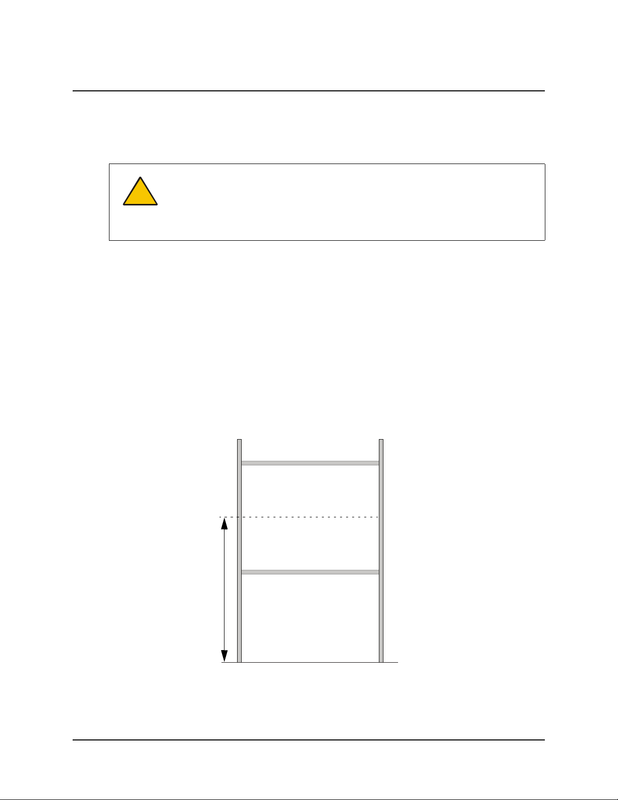
The optimal height from the floor to the center of the wall opening is 57 1/2" (146.1 cm).
The rough wall opening
should be larger than the
suggested minimum to
accommodate shim
material and to ensure the
finished wall opening has
Typically, the center
of the wall opening is
57 1/2" (146.1 cm)
from the floor.
99-00479-03 REV B0 Creating the Wall Opening 5
square corners.
Page 12
NOTE: Most measurements in this guide assume that your wall opening, and therefore the middle
of the screen, is at this height. For the 2876 or 2976, if you place the screen at a different height,
you’ll have to raise or lower the mirror stand so that the center of the projected image is aimed at
the center of the screen. In particular, the vertical center of the image should align with the center
of the screen.
CAUTION
Don’t remove the protective cover from the rear surface of the interactive
whiteboard until you’ve completely installed it in the wall opening.
To create the wall opening
1. Select an appropriate location for the opening. While this may be dictated by the location of
the projection room, an ideal site is a central area that is visible from all parts of the room, at a
comfortable height for writing. The optimal height of the wall opening, as measured from the
floor to the center of the wall opening, is 57 1/2" (146.1 cm).
2. Cut a rough hole through the wall at the appropriate height that, when finished with wood stud
framing, has the following minimum dimensions:
– For a 1710, the finished wall opening must measure at least 53 7/8" W × 43 1/4" H
(136.8 cm × 110.0 cm)
– For an 1810, the finished wall opening must measure at least 57 7/8" W × 46 1/4" H
(147.0 cm × 117.5 cm)
– For a 1910, the finished wall opening must measure at least 68 5/8" W × 54 3/8" H
(174.3 cm × 138.1 cm)
– For the 2876, the finished wall opening must measure at least 57 7/8" W × 46 1/4" H
(147.0 cm × 117.5 cm)
– For the 2976, the finished wall opening must measure at least 68 5/8" W × 54 3/8" H
(174.3 cm × 138.1 cm)
IMPORTANT
While these dimensions represent the minimum size for the opening, you
should make your opening 1/4" (0.6 cm) larger to accommodate shim
material and to ensure that your finished opening has right-angled corners.
6 Creating the Wall Opening 99-00479-03 REV B0
Page 13
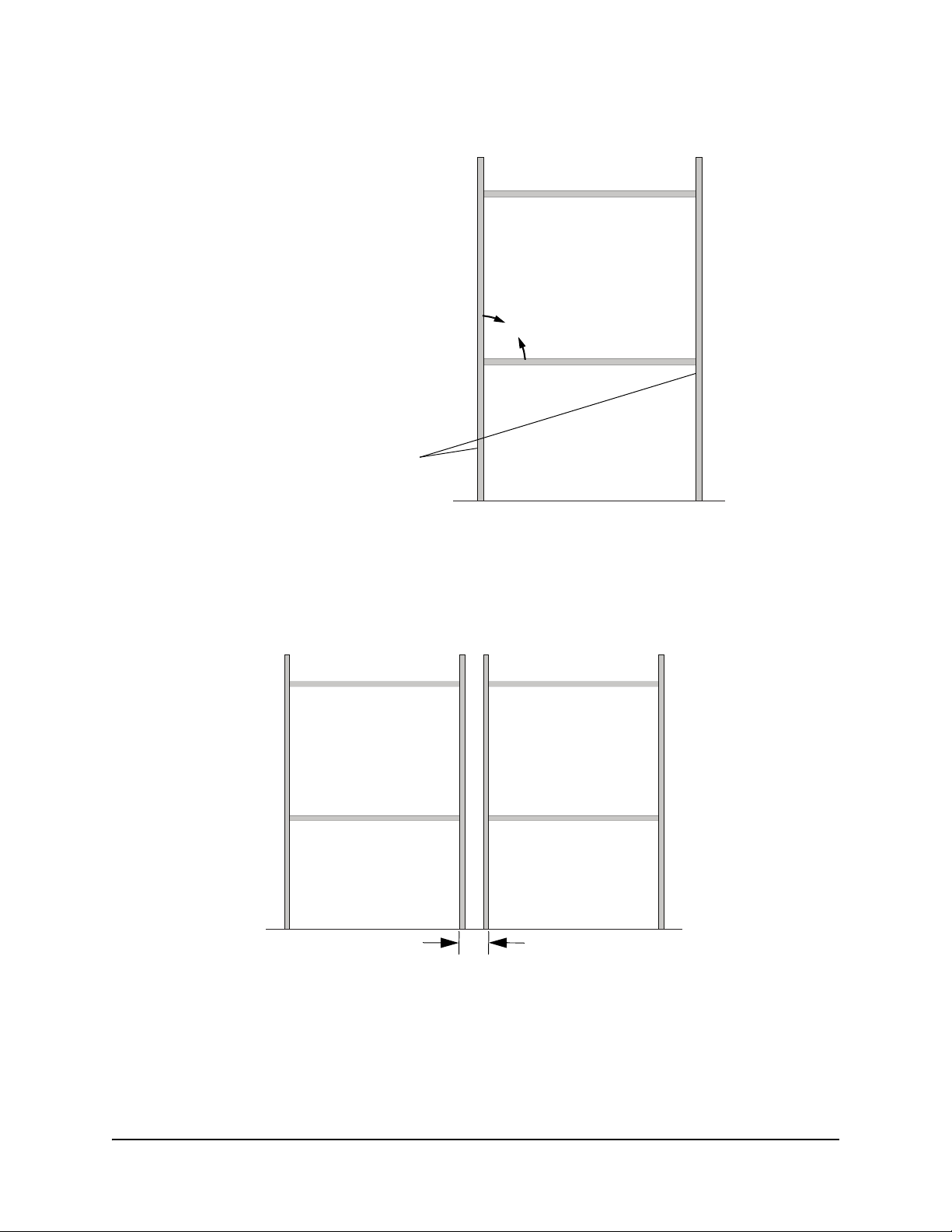
3. Frame the wall opening with vertical and horizontal wood framing.
The rough wall opening should be
larger than the suggested minimum to
accommodate shim material and to
ensure the finished wall opening has
square corners.
The rough wall opening must
have vertical studs running
from the floor to the ceiling.
90°
Dual Installation
If you want, you can install two in-wall units side by side. When you do this, you must leave a small
space between the interactive whiteboards. This space should be slightly greater than 1/4"
(0.6 cm), which means you must leave approximately 3 3/4" (9.5 cm) between the two wall
openings.
Leave approximately 3 3/4" (9.5 cm)
between the two wall openings.
99-00479-03 REV B0 Creating the Wall Opening 7
Page 14

8 Creating the Wall Opening 99-00479-03 REV B0
Page 15
Installing Your Interactive Whiteboard
In this section, you’ll:
• attach mounting brackets to the interactive whiteboard (this page)
• install the interactive whiteboard into the wall opening (page 12)
• create a wall opening for the cables (page 13)
• mount the pen tray assembly on the wall (page 14)
• (2876 or 2976 only) install the mirror stand in the projection room (page 17)
IMPORTANT
When you install the interactive whiteboard, make sure you can also remove it from
the wall opening, in case you need to service it later.
CAUTION
Don’t remove the protective cover from the rear surface of the SMART Board
interactive whiteboard until you have completely installed it in the wall opening. If
this cover is accidentally removed, don’t leave any fingerprints on the rear of the
screen. If you do smudge this surface, spray a soft cloth with alcohol-free glass
cleaner, and then gently and carefully dab the surface until the marks are removed.
Don’t spray the cleaner directly onto the rear of the screen.
Never, under any circumstances, apply isopropyl alcohol, water or acetone to the
rear surface of the interactive whiteboard. These fluids could damage the diffusion
coating, resulting in a permanent deterioration in display quality.
Attaching Mounting Brackets to the Interactive Whiteboard
Before you can mount the interactive whiteboard into the opening in your wall, you must attach the
L-shaped mounting brackets to both sides of the SMART Board interactive whiteboard.
The short side of the “L” (the narrow flange) attaches to the frame of the interactive whiteboard,
while the long side (the wide flange) projects from it. When you install the unit into the opening,
you’ll secure the long side (wide flange) of the bracket to the vertical wood framing.
Before you complete the following procedure, obtain the four hex screws, the four split
lockwashers and the 3/16" hex key from the accessory kit. You’ll also need the two mounting
brackets.
99-00479-03 REV B0 Installing Your Interactive Whiteboard 9
Page 16
To attach the mounting brackets to the interactive whiteboard
1. Place foam or a soft cloth onto a smooth, flat surface upon which you can rest the frame of the
interactive whiteboard.
2. Carefully place the interactive whiteboard face down on the foam or soft cloth. Take care to not
bend the interactive whiteboard.
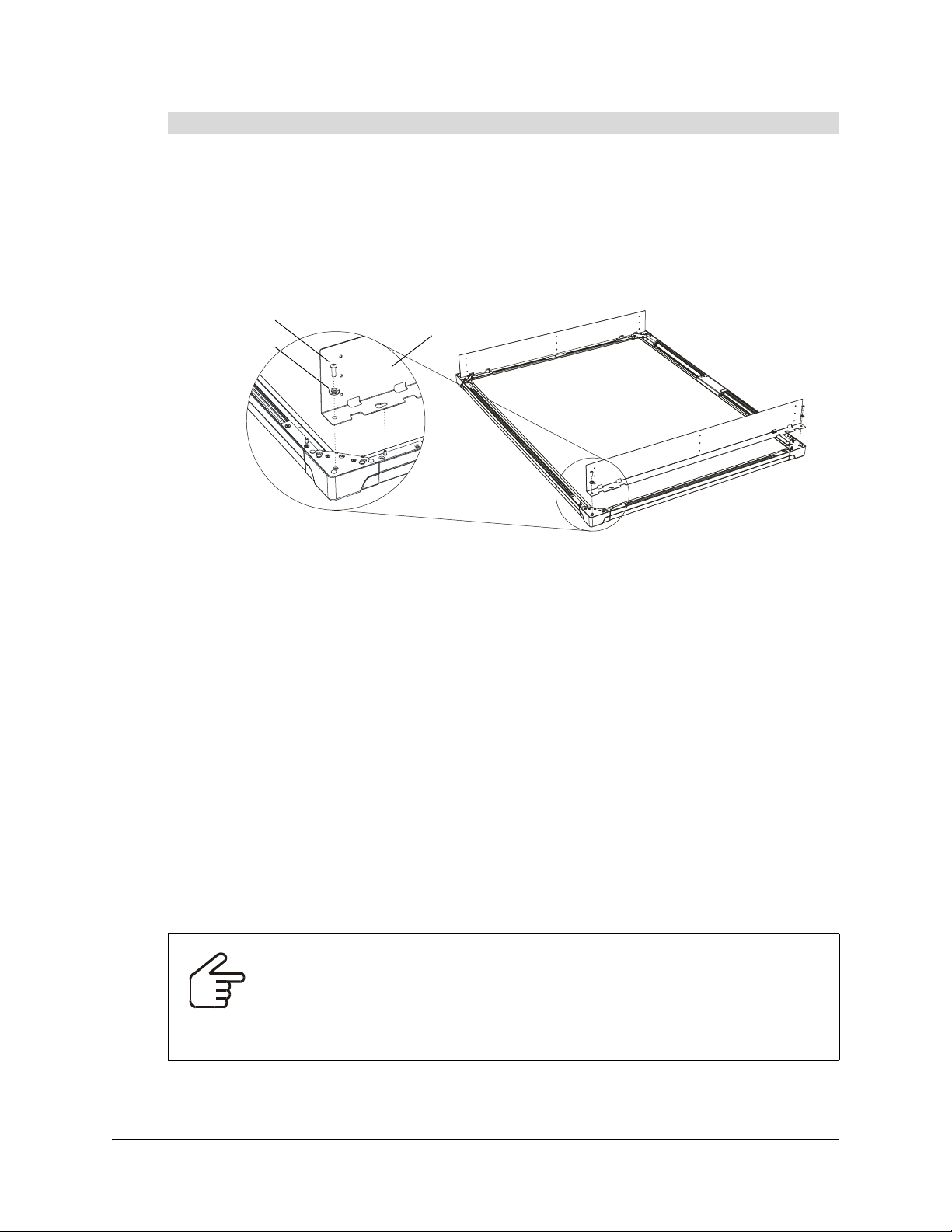
3. Position each L-shaped mounting bracket against the frame, as shown below. Align the screw
hole and post in each corner of the frame with the screw hole and keyhole in the bracket.
Screw
Lockwasher
Mounting
Bracket
4. Slip each of the four screws through a split lockwasher, and then insert them into the
appropriate bracket holes at the top and bottom of each bracket.
5. Tighten all screws with the supplied hex key so that the mounting brackets are securely
attached to the frame of the interactive whiteboard.
Install the Interactive Whiteboard in the Wall Opening
When you have attached the mounting brackets to the interactive whiteboard, you can install it into
the wall opening. You’ll need the No. 10 wood screws from the accessory kit and a Phillips® No. 2
screwdriver (not supplied).
NOTE: You’ll have screws left over when you’ve finished the installation.
For a perfectly flush fit, you can make shallow depressions or indentations in the drywall or
wallboard material at the edge of the wall opening. These indentations will accommodate the
screw heads and posts that protrude from the rear of the frame. When the unit is installed, you
won’t see these indentations, because the frame will cover them. To achieve this flush installation,
make three depressions on each side (six in total), with each depression approximately 1/2"
(1.3 cm) in diameter and 3/8" (1.0 cm) deep.
IMPORTANT
Before you install the interactive whiteboard into the wall, check that the wall is
even.
If you fit a large interactive whiteboard into an uneven wall, it is important that you
don’t flex the interactive whiteboard by forcing it to fit flush with the wall. The
interactive whiteboard has to be flat (not twisted or warped) for its digital cameras
to work correctly.
10 Installing Your Interactive Whiteboard 99-00479-03 REV B0
Page 17
Mounting
Bracket
Make three depressions
in the wallboard material
on each side for flush
installation.
Wallboard
Frame of Interactive
Whiteboard
Stud
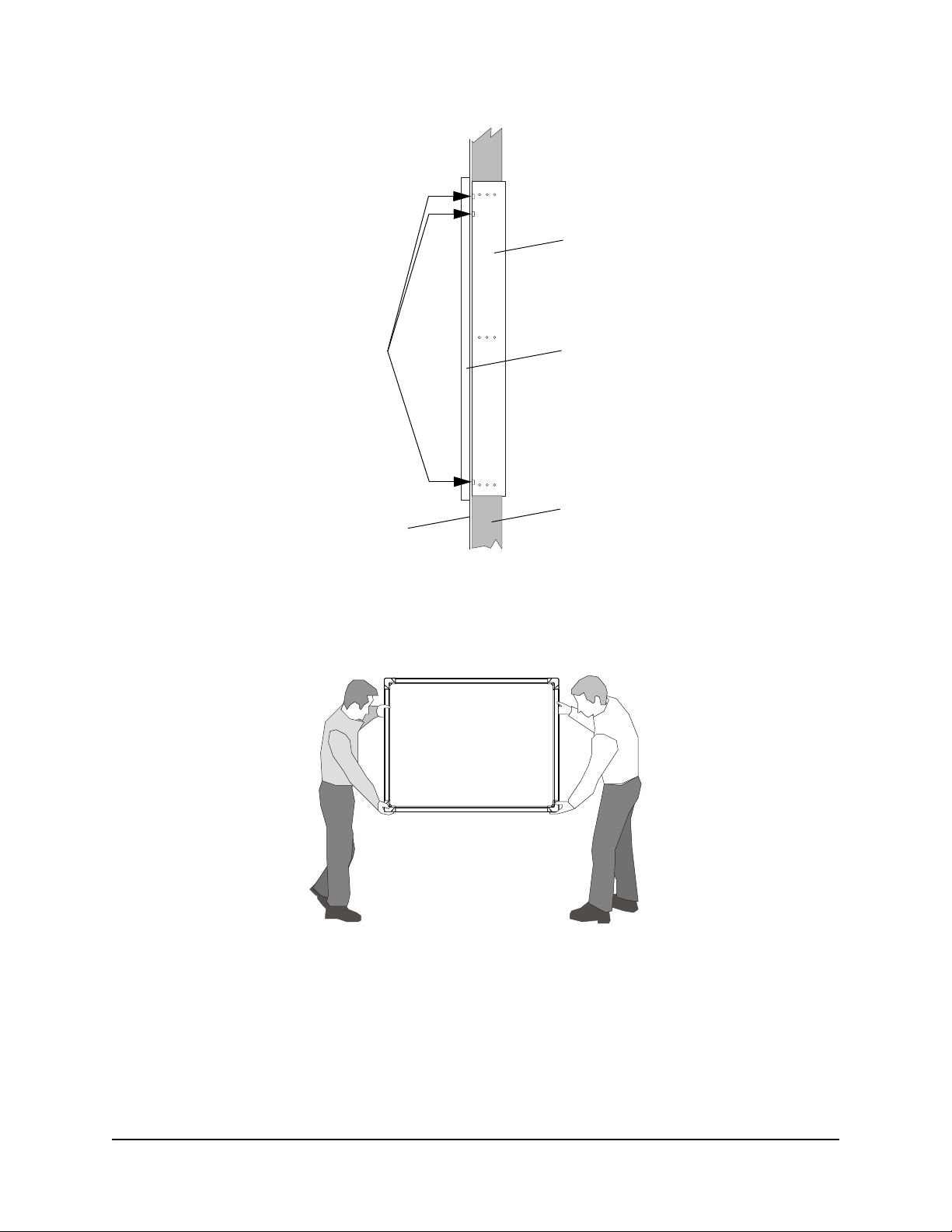
For safety, lift the interactive whiteboard with the assistance of another person. You and your
assistant should stand at either side of the screen, supporting its weight at the bottom corners
while balancing the top with your other hand. Your assistant should continue to hold the interactive
whiteboard in place while you secure the mounting brackets to the wood framing.
99-00479-03 REV B0 Installing Your Interactive Whiteboard 11
Page 18
To install the interactive whiteboard in the wall opening
CAUTION
If you’re installing the interactive whiteboard in an uneven wall, never push the
interactive whiteboard to ensure it is flush with the wall. Instead, allow the
interactive whiteboard to hang naturally, and then insert the screws, as this will
ensure that the interactive whiteboard is flat.
1. Lift the SMART Board interactive whiteboard with the mounting brackets attached, and place it
into the prepared wall opening. Shim as necessary.
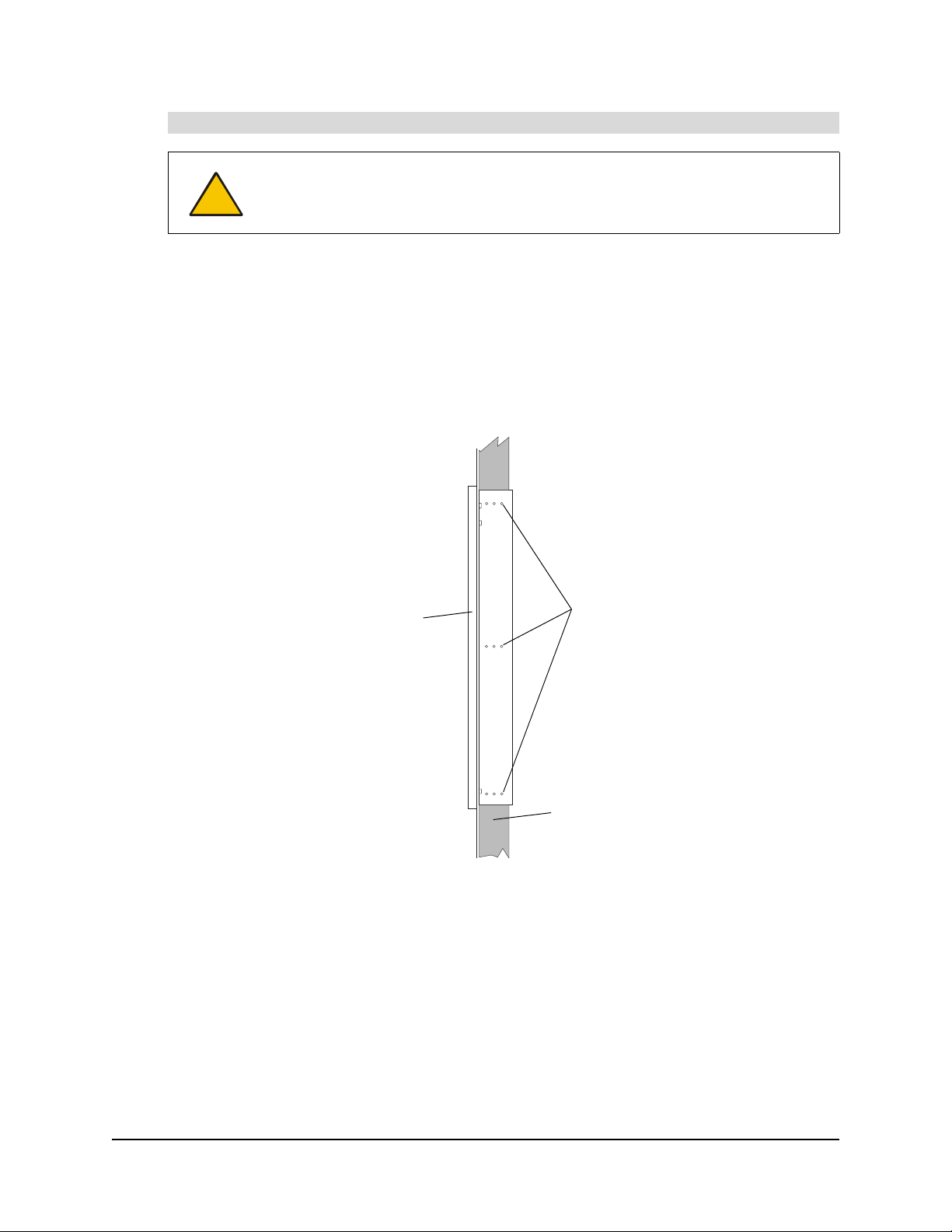
2. From the projection room side, insert one screw through the top row of holes in each mounting
bracket.
3. From the projection room side, insert one screw through the middle row and another through
the lower row of holes in each mounting bracket and into the vertical wood framing.
4. From the projection room side, if possible, insert an additional screw through each row of
holes in each mounting bracket.
Front Side of SMART Board
Interactive Whiteboard
Frame of Interactive Whiteboard
Projection Room Side
Insert a screw into each row
of holes in each bracket
Stud
5. Remove the covering from the rear surface of the interactive whiteboard.
12 Installing Your Interactive Whiteboard 99-00479-03 REV B0
Page 19
Creating a Wall Opening for the Cables
To create an opening in the wall for the cables, you’ll need the SMART Pen Tray Wall-Mount
Tem pl at e from the accessory kit. You’ll also need a measuring tool, a level and the appropriate
tools for creating a wall opening.
To create a wall opening for the cables
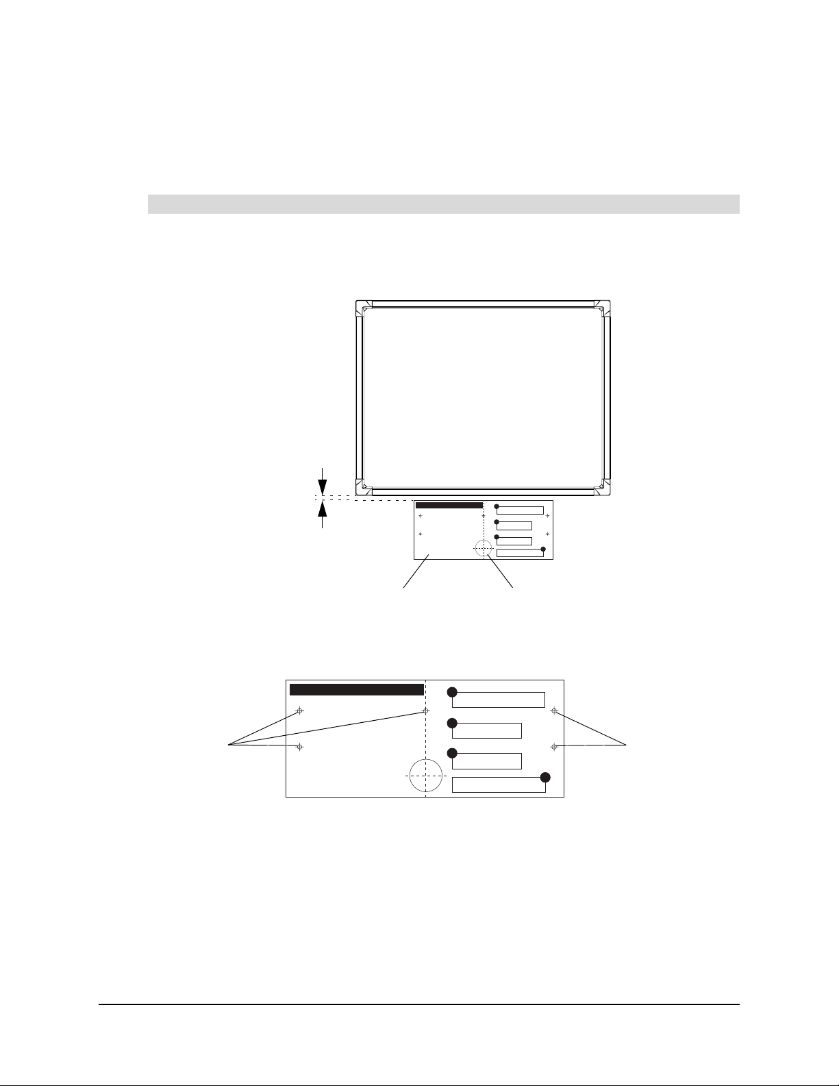
1. Position the top edge of the SMART Pen Tray Wall Mount Template 1" (2.5 cm) below the
bottom edge of the interactive whiteboard frame, making sure the template is level and aligned
with the center of the interactive whiteboard.
NOTE: The illustration
is not to scale.
SMART Board Interactive Whiteboard
(Front View)
Center the template
1" (2.5 cm) below the
interactive whiteboard
SMART Pen Tray Wall-Mount Template
Temp lat e
Cable Opening Location
2. Use the template to mark the center of a 2 3/8" (6.0 cm) diameter hole for the cables on the
wall, as well as five drywall anchor locations. Later, you will use these drywall anchor locations
to attach the pen tray to the wall.
SMART Pen Tray Wall-Mount Template
Anchor
Locations
SMART Pen Tray Wall-Mount Template
Anchor
Locations
NOTE: The illustration
is not to scale.
NOTE: The locations for these screws probably won’t be at the wall studs. However, if they
are, you can use a No. 8 × 1 1/2" wood screw (not supplied) or a self-drilling metal screw (not
supplied) without a drywall anchor at each location.
3. Remove the template.
4. Create a hole in the wall for the cables using the appropriate tool.
5. Insert a plastic grommet into each side of this wall opening.
99-00479-03 REV B0 Installing Your Interactive Whiteboard 13
Page 20

Mounting the Pen Tray on the Wall
When your interactive whiteboard is in place, you need to attach the pen tray to the wall.
To perform this procedure, you’ll need the following items from the accessory kit:
• five E-Z insert drywall anchors
• five No. 8 × 1 1/4" screws
• the pen tray, with its wall-mount bracket and the IR receiver attached (they’re inside a bag for
protection from electrostatic discharge)
• the USB adapter or 20' (6.1 m) serial cable (if you ordered it)
• the wireless keyboard
• four pens
• the eraser barrier and the eraser
You’ll also need a Phillips No. 2 screwdriver (not supplied).
To mount the pen tray
1. Using a Phillips No. 2 screwdriver, insert the drywall anchors into the marked locations. You
made these marks when you were creating the wall opening for the cables.
NOTE: The marked locations probably won’t be at the wall studs. However, if they are, you
can use a No. 8 × 1 1/2" wood screw (not supplied) or a self-drilling metal screw (not supplied)
without a drywall anchor at each location.
2. Partially insert a screw into each of the top three drywall anchors using the Phillips
screwdriver. Leave at least 1/8" (0.3 cm) of the screw protruding, so you can hang the pen tray
mounting bracket.
NOTE: The illustration
is not to scale.
Insert a screw into the top
three drywall anchors.
Leave at least 1/8" (0.3 cm)
of the screw protruding.
Wall Opening for Cables
14 Installing Your Interactive Whiteboard 99-00479-03 REV B0
Page 21

3. Connect the modular communication cable to the modular jack at the back of the pen tray.
4. The procedure for connecting the pen tray to your computer varies, depending on whether
you’re connecting the pen tray to a USB or serial connector on your computer. Your interactive
whiteboard comes with a SMART USB adapter cable. However, you can order an optional
DB9-to-DB9 serial cable if you need to connect to a serial connector on your computer. Either:
– connect one end of the supplied USB adapter to the DB9 connector at the back of the pen
tray
– if you ordered the DB9 serial cable, connect it to the DB9 connector at the back of the pen
tray
5. Slide the three keyholes in the pen tray mounting bracket onto the protruding screws on the
wall.
Keyholes
Modular Jack
DB9 Connector
Pen Tray
Pen Tray Mounting Bracket
6. Try to move the pen tray to check its stability. If it moves too freely, take it off the wall, tighten
the screws slightly, and then return it to the wall.
7. Using the Phillips screwdriver, insert screws into the two holes in the mounting bracket
underneath the pen tray. These screw locations line up with the drywall anchors that you
inserted earlier.
8. Ensure the IR receiver is in its slot. If the computer is in the projection room, feed the IR
receiver cable through the wall opening for the cables. Run this cable to the computer but
don’t connect it. You will connect this cable to the computer later.
9. Snap the eraser wall into place. Put the eraser and the four pens in their appropriate slots on
the pen tray. Place the wireless keyboard on the keyboard bracket.
Eraser
Eraser
Wall
10. Slide the other ends of the communication cable and the USB adapter through the wall
opening for the cables. You connected both of these cables to the pen tray earlier.
99-00479-03 REV B0 Installing Your Interactive Whiteboard 15
Page 22

Installing the Mirror Stand (2876 and 2976 Only)
If you’re installing a 2876 or a 2976, you need to install the mirror stand in the projection room
behind the interactive whiteboard.
CAUTION
Be very careful if you have to move or adjust the mirror stand after you’ve removed
the cross braces (page 17). Don’t apply pressure to any part of the screen opening
and in particularly to the upper corners.
Avoid pushing the mirror stand because excessive pressure may cause it to lose its
square shape. If you do move or adjust the stand, either lift it from the bottom or
push it at the bottom.
Don’t Push at the Top or Sides
The optimal position for your mirror stand depends on your model of interactive whiteboard.
• For the 2876, the maximum distance between the lower cabinet of the mirror stand and the
wall surface upon which you mount the interactive whiteboard is 3 1/4" (8.3 cm).
• For the 2976, you must allow at least 15" (38.1 cm) between the lower cabinet of the mirror
stand and the wall surface upon which the interactive whiteboard is mounted.
You’ll also need to consider the thickness of your wall when you position the mirror stand.
When the mirror stand is in place, you must align its opening horizontally and vertically with the
interactive whiteboard. To do this, adjust the leveling legs, which are raised above the casters for
shipping. Once all the legs are adjusted, the casters should be approximately 1/2" (1.3 cm) above
the floor.
NOTE: If you didn’t install the interactive whiteboard at the recommended height (page 10),
position the mirror stand so the center of the projected image is aimed at the center of the screen.
16 Installing Your Interactive Whiteboard 99-00479-03 REV B0
Lift or Push at the Bottom
Page 23

You may have to readjust the leveling legs as you position the mirror stand. First, raise the stand to
the approximate height by adjusting the front legs, followed by the back legs. Finally, level the
mirror stand by making fine adjustments on the legs until the stand is perfectly level.
To adjust the legs, you’ll need a 1/2" (1.3 cm) flat or adjustable wrench, or you can use the 9/16"
wrench that comes with the mirror stand. You’ll also need two 15/16" flat or adjustable wrenches
for the leveling process.
To install the mirror stand
1. Wheel the mirror stand into the projection room and remove the cross braces from the screen
opening.
2. Remove the strap at the front of the mirror stand. You’ll have to position the mirror to adjust the
projected image when you set up the projector.
3. If you want the computer to be in the projection room, slide it into the mirror stand.
Slide the computer
into the mirror stand
NOTE: For ease of use, ensure you can access the computer’s power switch and drives. If
you have limited access at the front of the mirror stand, slide the computer into the mirror
stand with the front of the computer facing the rear of the mirror stand.
4. Align the opening of the mirror stand horizontally with the installed screen. Using the wall
brackets as your guide, lift or push at the bottom sides to center the mirror stand between the
brackets.
– For the 2876, the maximum distance between the lower cabinet of the mirror stand and
the wall surface upon which you mount the interactive whiteboard is 3 1/4" (8.3 cm).
– For the 2976, you must allow at least 15" (38.1 cm) between the lower cabinet of the
mirror stand and the wall surface upon which the interactive whiteboard is mounted.
5. Align the mirror stand vertically behind the installed screen by adjusting the leveling legs.
Raise the mirror stand so that the front opening is the same distance from the top edge of the
screen as it is from the bottom edge. Depending on your installation, the leveling legs may
raise the casters approximately 1/2" (1.3 cm) from the floor.
99-00479-03 REV B0 Installing Your Interactive Whiteboard 17
Page 24

i. Raise the jam nut on the leveling leg.
Jam Nut
Mirror Stand Base
ii. Using a 1/2" flat or adjustable wrench, grip one leveling leg in the 1/2" (1.3 cm) flat area
just above the foot.
The flat area just
above the foot
iii. Rotate the wrench and leg until the mirror stand reaches the appropriate height.
iv. Rotate the jam nut downward until it reaches the mirror stand base. Tighten it with a
15/16" flat or adjustable wrench.
Jam Nut
Mirror Stand Base
Rotate the jam
nut downward ...
... until it reaches the
mirror stand base
18 Installing Your Interactive Whiteboard 99-00479-03 REV B0
Page 25

Connecting the Cables
To enable communication between all the components in your In-Wall Rear Projection SMART
Board interactive whiteboard, you must connect the appropriate cables to the computer and the
interactive whiteboard. You also need to connect the interactive whiteboard to the supplied power
supply.
To connect the cables
1. If you haven’t done so already, shut down your computer before connecting any cables.
2. Connect one end of the modular cable to the interactive whiteboard’s communications hub
(see the illustration below). You’ve already connected the other end of this cable to the pen
tray.
3. Connect the power supply cable to the interactive whiteboard’s communications hub. This
cable is in your accessory kit.
Modular Jack
Power Connector
Communications
Hub
4. Connect the power cable to the power supply cable.
5. Connect the other end of the power cable to a power outlet.
6. The next step of these instructions depends on whether you’re connecting the pen tray to a
USB or serial connector on your computer. Your interactive whiteboard comes with a SMART
USB adapter cable that connects to a USB connector on your computer. However, you can
order an optional DB9-to-DB9 serial cable if you need to connect to a serial connector on your
computer.
99-00479-03 REV B0 Connecting the Cables 19
Page 26

– To connect the computer using the SMART USB adapter cable, connect the USB adapter
to a USB connector on the computer. You previously connected the other end of this
adapter when you mounted your pen tray to the wall (page 14).
CAUTION
Don’t connect the SMART USB adapter cable to the computer until after
you’ve installed SMART Board software (page 3).
– To connect the computer using the optional DB9 serial cable, connect the serial cable to a
DB9 serial connector on the computer. You previously connected the other end of this
cable when you mounted your pen tray to the wall (page 14).
NOTE: If your serial cable has a power port on the back of the DB9 connector, you don’t
need to use it. Power is supplied to the pen tray through its power supply. However, you
won’t damage anything if you connect the power supply to this port.
7. Attach the two PS/2 connectors from the IR receiver to the computer’s keyboard and mouse
connectors.
NOTES
– You can increase the length of the USB or serial cable by using a serial extension cable
(not supplied).
– You can increase the length of the PS/2 cable by using two 6' (1.8 m) extension cables.
20 Connecting the Cables 99-00479-03 REV B0
Page 27

Setting up the Projector
This section of the guide provides general guidelines for installing any projector (see below).
However, if you have a 2876 or a 2976, this section also includes detailed instructions on installing
an NEC VT676 projector.
After you’ve installed the projector and aligned its image with the center of the screen, you can
then make fine adjustments to the projected image (page 24).
Installing a Projector
The following general guidelines will help you install your projector. For specific information, see
the manufacturer’s instructions supplied with your projector.
To install a projector
1. Set the computer’s screen resolution to match the projector’s optimal resolution.
– For information on your projector’s optimal resolution, see the instructions supplied with
your projector.
– For information on how to change your computer’s screen resolution, see the instructions
supplied with your operating system.
2. Place the projector on a projector platform or stand:
– if you’re not using a mirror, point the lens of the projector at the center of the screen.
NOTE: To help center the image on the interactive whiteboard, place the projector
squarely on its stand, perpendicular to the screen.
– if you’re using a mirror, point the lens of the projector towards the center of the mirror.
3. Connect the projector to the computer and to a power outlet by following the instructions
supplied with your projector.
4. If you’re using one or two mirrors to project the correct image size onto the screen, adjust
them so that you have a square image on the screen.
5. If the image is reversed when you look at it from the front, switch the projector to rearprojection mode. For information on how to switch to rear-projection mode, see the
instructions supplied with your projector.
Installing the VT676 Projector into the Mirror Stand (2876 and 2976 only)
You must install the VT676 projector inside the mirror stand, and then connect it to the computer.
CAUTION
Never touch the rear of the screen or brush against it. If you do smudge this
surface, lightly spray alcohol-free glass cleaner onto a soft cloth and dab the
affected area to remove the marks. Never apply isopropyl alcohol, water or
acetone, as these fluids will damage the diffusion coating and permanently reduce
the display quality.
99-00479-03 REV B0 Setting up the Projector 21
Page 28

To install the VT676 projector into the mirror stand
1. Lift the projector into the cabinet. Lower it onto the projector plate so that the security screws
go through the keyhole slots. Carefully allow the projector to slide backwards until it comes to
a halt.
2. Tighten the three security screws using the TORX® key in the accessory kit.
3. Locate the projector mount adjustment block in the kit supplied with the projector. Also, look at
the top of the projector to find the optimum installation position sticker.
Approximate
location of
Projector Mount Adjustment Block
installation
sticker
NOTE: The installation sticker displays two settings. Use the 3000i setting.
4. Using the 7/16" nut driver that shipped with the projector, loosen the three locking bolts
indicated below.
22 Setting up the Projector 99-00479-03 REV B0
Page 29

5. Slide the projector mount adjustment block under each corner of the projector plate and adjust
the projector plate to the optimum installation position as indicated on the sticker. To adjust the
projector plate, loosen or tighten the knob in each corner.
6. Using the 7/16" nut driver, tighten the three locking bolts that you loosened in step 3.
7. Attach the projector’s RGB cable to the Computer 1 IN connector on the projector’s
connection panel.
8. Connect the projector’s power cable to the power adapter and connect the adapter to the AC
IN socket on the projector’s connection panel.
9. Connect the other end of the RGB cable to the computer.
10. Connect the other end of the power cable to a power outlet.
99-00479-03 REV B0 Setting up the Projector 23
Page 30

Making Fine Adjustments to the Projected Image
When you’ve properly positioned the projector or the mirror stand, you can make fine adjustments
to obtain a correctly projected image on the interactive whiteboard. An aligned image fits squarely
on the interactive screen with a margin of about 1/2" (1.3 cm) on all sides.
1/2" (1.3 cm)
Margin
Projected
Image
This section of the guide provides general guidelines for adjusting the projected image from any
projector (see below). However, if you have a 2876 or a 2976, this section also includes detailed
instructions on adjusting the projected image from an NEC VT676 projector (page 25).
NOTE: A keystone image occurs when the edges of your image are not parallel. Your projector
may have a feature for automatically correcting this issue. However, don’t use this feature. If the
edges of your projected image are not parallel, correct it using the methods detailed on the
following pages.
Projected
Image
Margin
Areas
To align and adjust the projected image
1. If the left and right edges of your projected image are not parallel, raise or lower the projector
at the front or back until the edges are parallel.
2. If the top and bottom edges are not parallel, turn the projector slowly until the edges are
parallel.
3. Adjust the projected image using small, slow movements until you’re satisfied with the image.
– Correct the image size by moving the projector forwards or backwards until the image
correctly fills the interactive screen.
– Correct the image’s horizontal and vertical position by adjusting the height and position of
the projector platform or stand.
– Create a clear image by adjusting the projector’s focus function.
NOTE: The method for changing the projected image depends on your projector. For more
information, see the instructions supplied with your projector.
24 Setting up the Projector 99-00479-03 REV B0
Page 31

To align and adjust the projected image on the 2876 or the 2976
1. To focus the image, adjust the Zoom lever on the projector which has been modified for this
purpose.
Zoom Lever
Do not move this ring
Do not move this ring
CAUTION
Don’t adjust the ring that surrounds the short-throw, customized projector
lenses, even though the NEC VT676/670/575/470/47 User’s Manual states
that you should use this ring to obtain the best focus. You must disregard this
information.
Rather, use the Zoom lever on the projector. Again, contrary to the NEC
VT676/670/575/470/47 User’s Manual, the Zoom lever will not adjust the
image size on the screen.
2. Using the 7/16" nut driver, loosen the three locking bolts identified in the figure below.
3. To adjust the image laterally, slide the projector to the left or right.
99-00479-03 REV B0 Setting up the Projector 25
Page 32

4. To adjust roll:
i. Tighten or loosen the knobs on the left of the projector plate until you have the required roll
adjustment. Adjust these knobs by the same amount or else you will change the vertical
adjustment of the image.
ii. If you can’t tighten the knobs on the left of the projector plate, adjust the roll by loosening
the knobs on the right of the projector plate
5. If you need to make large changes to the image size, you should move the mirror stand closer
to or farther from the interactive whiteboard. However, to make small changes to the image
size:
i. Loosen the three security screws in the projector plate using the TORX key in the
accessory kit.
ii. Slide the projector backward or forward.
iii. When your image is the correct size, tighten the security screws.
26 Setting up the Projector 99-00479-03 REV B0
Page 33

6. To move the image up or down:
i. Loosen the upper thumbscrews on both sides of the small mirror.
Loosen upper
thumbscrew on
each side.
Pivot
(do not loosen)
ii. Gently push the mirror away from you to lower the image, or pull it towards you to raise the
image.
iii. When the mirror is in position, there should be minimal keystone error. If there is a
significant keystone error, re-adjust the small mirror, even if this places the image too high
or too low on the screen. Tighten the thumbscrews.
iv. If the image is still too high or too low, tighten or loosen the knobs at the front of the
projector plate until you have the required vertical adjustment. Adjust these knobs by the
same amount or else you will change the roll adjustment of the image.
.
If you can’t tighten the front knobs any further, you can change the vertical adjustment by
loosening the knobs at the rear of the projector plate
v. If the image is still too high or too low, adjust the mirror stand’s feet to raise or lower the
image to the correct position (page 18).
99-00479-03 REV B0 Setting up the Projector 27
Page 34

7. Using the 7/16" nut driver, tighten the three locking bolts that you loosened in step 2.
28 Setting up the Projector 99-00479-03 REV B0
Page 35

Using the Interactive Whiteboard
When your interactive whiteboard is installed, you need to:
• configure SMART Board software
• start SMART Board software
• calibrate the cameras
• orient the interactive screen
This section also includes instructions on setting up your interactive whiteboard and basic
information on using SMART Board software. However, you should refer to the SMART Board
software online Help for detailed information on using all the software features.
Configuring SMART Board Software
After you install SMART Board software and connect the interactive whiteboard, your screen
becomes fully interactive. However, sometimes SMART Board software can’t locate the port that
your interactive whiteboard is connected to. If your screen isn’t touch sensitive, configure the port
in SMART Board software. If your interactive whiteboard is connected with a USB adapter, you’ll
have to disconnect the USB connector from your computer, and then reconnect it. For more
information, see the SMART Board software online Help.
Starting SMART Board Software
Start SMART Board software to access a wide range of software tools, such as Notebook
software, SMART Video Player, the SMART Keyboard and the Floating Tools.
When you start SMART Board software, the SMART Board icon appears in your system tray
(Windows computers) or in the Dock (Macintosh computers). Press this icon to view a menu of all
available software tools. For more information on using the tools in SMART Board software, see
the SMART Board software online Help.
• For Windows operating systems, select Start > Programs > SMART Board Software >
SMART Board Tools.
• For Macintosh computers, open the SMART Board Software folder and select SMART Board
Tools.
Calibrating the Cameras
Each digital camera in the interactive screen is calibrated to recognize the position of a pen tray
tool or your finger on the screen’s surface and to send this information to SMART Board software.
The software then interprets the information as mouse clicks or digital ink in the appropriate
location.
If the cameras become misaligned for any reason, you may notice gaps in your writing or an area
of the screen may become unresponsive to your touch. Fortunately, this problem is easily fixed by
performing a simple calibration procedure. For more information, see the SMART Board software
online Help.
99-00479-03 REV B0 Using the Interactive Whiteboard 29
Page 36

Orienting SMART Board Software
Although SMART Board software assigns a default orientation, you may want to perform an
orientation to ensure the greatest possible level of accuracy as the computer accurately tracks
your contact with the screen. For more information, see the SMART Board software online Help.
NOTE: You can start the orientation by pressing and holding both pen tray buttons simultaneously.
Starting the System Components
Your system consists of the interactive whiteboard, the projector and the computer. Your
interactive whiteboard is always ready to use but you may have to start the other components.
To start up the projector
If you purchased a projector separately from your interactive whiteboard, start up the projector
following the manufacturer’s instructions supplied with your projector.
If you received an NEC VT676 projector with your interactive whiteboard, start up the projector as
follows:
1. If you have not done so already, connect the projector’s power cable to a power outlet and turn
on the projector’s Main Power switch.
2. Press and hold the POWER ON button on the projector’s remote control for a minimum of two
seconds.
To start up the computer
1. Turn on your computer.
2. When the computer desktop appears on the interactive whiteboard, touch the screen.
– If the pointer appears and it tracks the movement of your finger, your interactive
whiteboard is ready to use.
– If the pointer appears but it doesn’t track the movement of your finger, you must configure
the COM port. For more information, see the SMART Board software online Help.
Shutting Down the System Components
Depending on your system preferences, you may choose to shut down your computer when the
interactive whiteboard isn’t in use. Similarly, you may choose to put the projector into standby
mode or shut it down when it’s not in use.
CAUTION
If your interactive whiteboard includes an NEC VT676 projector, please note that
this projector has been designed for use under normal operating conditions only.
Normal operating conditions are defined as product use that does not exceed eight
hours per day and 260 days per year. Exceeding these operating conditions could
cause projector damage. Damage caused by such extended use is not covered by
the product warranty.
30 Using the Interactive Whiteboard 99-00479-03 REV B0
Page 37

To shut down the computer
1. Close any open computer programs.
2. Shut down the computer.
To put the projector into standby mode
If you purchased a projector separately from your interactive whiteboard, put the projector into
standby mode by following the manufacturer’s instructions supplied with your projector.
If you received an NEC VT676 projector with your interactive whiteboard, put the projector into
standby by following the instructions below.
1. Press the POWER OFF button on the projector’s remote control.
The Power Off message appears.
2. Press the POWER OFF button on the projector’s remote control to confirm.
To shut down the projector
Shut down the projector following the manufacturer’s instructions supplied with your projector.
CAUTION
Don’t unplug the projector’s power cable or turn off the projector’s Main Power
switch until the fans have stopped and the Power indicator glows orange. Wait
several minutes for the projector’s fans to cool the lamp.
99-00479-03 REV B0 Using the Interactive Whiteboard 31
Page 38

32 Using the Interactive Whiteboard 99-00479-03 REV B0
Page 39

Maintaining the Interactive Whiteboard
This section includes instructions on cleaning the In-Wall Rear Projection SMART Board
interactive whiteboard. This section also explains how you can clean an NEC VT676 projector and
replace its projector lamp and filter.
Cleaning the Interactive Whiteboard
After writing on the screen, you may notice marks that appear to be scratches. These marks are
plastic residue that’s left when someone presses a pen very hard on the screen. Remove these
marks with your thumbnail, and then clean the area with whiteboard cleaner.
Avoid using abrasive erasers that may scratch the surface.
Periodically dust your In-Wall Rear Projection SMART Board interactive whiteboard. If your unit
has a mirror stand, dust the stand and the mirrors using a soft cloth. If you need to, use a standard,
alcohol-free glass cleaner.
Avoid using cleaning materials that may scratch the surface.
CAUTION
The cameras are well protected from dust and dirt, so you should only clean the lenses
occasionally. When you do so, don’t spray glass cleaner directly onto the lens. Instead, spray the
cleaner onto a cotton-tipped swab and rub it gently on the lens. If you allow excess glass cleaner
to flow into the crack between the frame and the screen, the fluid could damage the cameras.
If there is permanent marker ink on your screen, you can remove it by completely covering it with
the ink from a dry-erase marker (but not a low-odor marker), and then wiping the screen with a soft
cloth. If any trace of the original permanent ink remains, spray the area with standard, alcohol-free
glass or whiteboard cleaner, and wipe clean.
You can also use whiteboard cleaner, such as Expo
this product, cover the ink with the solvent, let it dry, and then erase the ink.
Don’t touch the rear of the screen. If you do smudge this surface, spray alcoholfree glass cleaner lightly on a soft cloth, and then gently dab the rear surface until
the marks are removed. Don’t spray the glass cleaner directly onto the rear of the
screen.
Don’t, under any circumstances, apply isopropyl alcohol, water or acetone to the
rear surface of the interactive whiteboard. These fluids could damage the diffusion
coating, resulting in a permanent deterioration in display quality.
®
Board Doctor. To remove permanent ink with
99-00479-03 REV B0 Maintaining the Interactive Whiteboard 33
Page 40

Cleaning the Projector
Clean the projector and its lens periodically.
If you purchased a projector separately from your interactive whiteboard, clean the projector and
its lens following the manufacturer’s instructions supplied with your projector.
If you have a 2876 or a 2976, clean your NEC VT676 projector and lens following the instructions
below.
To clean an NEC VT676 projector
1. Shut down the computer and the projector (see page 31).
2. Wipe the projector’s casing with a damp cloth. If this is insufficient, use a mild detergent, but
don’t use a strong detergent or a solvent, such as alcohol or thinner.
3. Carefully wipe the lens with lens paper.
CAUTION
Be careful not to scratch or mark the lens.
Cleaning a Filter
After every 100 hours of operation, a “Please Clean Filter” message appears on the bottom of the
screen.
To clean the filter
1. Clean the filter with a vacuum, as described on page 48 of the NEC VT676 User’s Manual.
NOTE: If the projector room is dusty, clean the filter more often, but be careful not to touch the
rear surface of the screen.
2. To clear the “Please Clean Filter” message, reset the filter usage meter as follows.
i. Press the Menu button on the projector remote control.
ii. Press the down arrow to highlight the Default option.
iii. Press the Enter button.
iv. Press the down arrow to highlight the Clear Filter Usage option.
v. Press the Enter button.
A message appears asking for confirmation.
vi. Select Yes and press the Enter button.
vii. Press the Exit button twice to close the menu.
34 Maintaining the Interactive Whiteboard 99-00479-03 REV B0
Page 41

Replacing the Projector Lamp and Filter in an NEC VT676 Projector
When the lamp nears the end of its natural life, a message appears prompting you to replace it. If
the lamp reaches the end of its natural life, the projector automatically goes into Standby mode
and stays in Standby mode until you replace the lamp.
CAUTIONS
You can view the remaining lamp time as a percentage of its expected life and the length of time
the lamp has been in use.
Only replace the projector lamp with the NEC VT75LPE lamp. These lamps are
available from NEC or SMART. Don’t use any other lamps.
Never touch the rear of the interactive screen. If you do smudge this surface, lightly
spray alcohol-free glass cleaner onto a soft cloth and dab the affected area to
remove the marks. Never apply isopropyl alcohol, water or acetone, as these fluids
will damage the diffusion coating and permanently reduce the display quality.
To view the lamp hour meter
1. Press the Menu button on the projector remote control.
2. Press the down arrow to highlight the Information option.
The Information sub-menu displays the remaining lamp time as a percentage of its expected
life and the length of time the lamp has been in use.
3. Press the Exit button to close the menu.
To replace the projector lamp and filter
1. Shut down the computer and the projector (see page 31).
CAUTION
After you shut down the projector, wait at least one minute before you unplug it.
2. Disconnect all of the cables from the projector.
3. Using a pencil, mark the projector plate with the current position of the three screws that attach
the projector to the plate.
4. Loosen but do not remove these three security screws using the TORX key in the accessory
kit. Carefully allow the projector to slide backwards until it stops.
NOTE: Do not change the position of the four height adjustment knobs.
5. Reach into the cabinet, slide the projector forward, lift it off the plate and remove it from the
cabinet
6. Set the projector on a flat surface.
WARNING
7. Replace the lamp according to the instructions on page 50 of the NEC VT676 User’s Manual.
Do not touch or replace the projector lamp (which will be very hot) for at least
an hour after turning off the projector.
99-00479-03 REV B0 Maintaining the Interactive Whiteboard 35
Page 42

8. Replace the projector filter according to the instructions on page 48 of the NEC VT676 User’s
Manual. You’ll receive this filter with your replacement lamp.
9. Lower the projector onto the projector plate so that the screws go through the keyhole slots.
Carefully allow the projector to slide backwards until it comes to a halt.
10. Slide the projector forward until the three screws are in the three marked positions you made
in step 3. Tighten the three screws using the TORX key.
11. Connect all of the projector’s cables.
12. Start up the projector and the computer (see page 30).
To clear the lamp hour meter
1. Press the Menu button on the projector remote control.
2. Press the down arrow to highlight the Default option.
3. Press the Enter button.
4. Press the down arrow to highlight the Clear Lamp Hour Meter option.
5. Press the Enter button.
A message appears asking for confirmation.
6. Select Yes and press the Enter button.
7. Press the Exit button twice to close the menu.
36 Maintaining the Interactive Whiteboard 99-00479-03 REV B0
Page 43

Appendix A: Specification Drawings
NOTE: All dimensions within this chapter are ± 1/8" (0.3 cm).
1710 Front and Side Views
57 3/8" (145.8 cm)
Active Screen Area
52 3/4" W × 39 5/8" H
(134.0 cm × 100.7 cm)
(4:3 aspect ratio)
44"
(111. 8 cm)
Diagonal 66"
(167.6 cm)
NOTE: The illustration
is not to scale.
Pen Tray
NOTE: The illustration
is not to scale.
Typically
1"
(2.5 cm)
2 5/8"
(6.7 cm)
38 1/4" (97.2 cm)
Keyboard/IR
Receiver Bracket
Drywall
Mounting
Bracket
Pen Tray
(mounts to wall)
Stud
9 5/8"
(24.4 cm)
4 5/8"
(11.8 cm)
99-00479-03 REV B0 Appendix A: Specification Drawings 37
Page 44

1710 Wall Opening
i
Minimum
43 1/4"
(110.0 cm)
Typically, the middle
of the screen is
57 1/2" (146.1 cm)
from the floor.
Square-Finished Wall Opening
Minimum
53 7/8" (136.8 cm)
Rough wall opening should be 1/4" (0.6 cm)
larger than the suggested minimum to
accommodate shim material and to ensure
square-finished corners.
NOTE: The illustration
s not to scale.
Hole for Cables
(centered on wall opening)
2 3/8" (6.0 cm) diameter
27 1/2" (69.9 cm)
(based on 57 1/2" (146.1 cm)
to the middle of the screen)
The rough wall opening must have vertical
studs running from the floor to the ceiling.
38 Appendix A: Specification Drawings 99-00479-03 REV B0
Page 45

1810 Front and Side Views
61 3/8" (155.9 cm)
Active Screen Area
56 3/4" W × 42 5/8" H
(144.2 cm × 108.3 cm)
(4:3 aspect ratio)
NOTE: The illustration
is not to scale.
47"
(119.4 cm)
2 5/8"
(6.7 cm)
Diagonal 71"
(180.3 cm)
38 1/4" (97.2 cm)
Pen Tray
Keyboard/IR
Receiver Bracket
Drywall
Mounting
Bracket
NOTE: The illustration
is not to scale.
Typically
99-00479-03 REV B0 Appendix A: Specification Drawings 39
1"
(2.5 cm)
Pen Tray
(mounts to wall)
Stud
9 5/8"
(24.4 cm)
4 5/8"
(11.8 cm)
Page 46

1810 Wall Opening
Minimum
46 1/4"
(117.5 cm)
Typically, the middle
of the screen is
57 1/2" (146.1 cm)
from the floor.
Square-Finished Wall Opening
Minimum
57 7/8" (147.0 cm)
Rough wall opening should be 1/4" (0.6 cm)
larger than the suggested minimum to
accommodate shim material and to ensure
square-finished corners.
NOTE: The illustration
is not to scale.
Hole for Cables
(centered on wall opening)
2 3/8" (6.0 cm) diameter
26" (66 cm)
(based on 57 1/2" (146.1 cm)
to the middle of the screen)
The rough wall opening must have vertical
studs running from the floor to the ceiling.
40 Appendix A: Specification Drawings 99-00479-03 REV B0
Page 47

1910 Front and Side Views
72 1/4" (183.5 cm)
Active Screen Area
67 1/4" W × 50 3/8" H
(170.8 cm × 128.0 cm)
(4:3 aspect ratio)
NOTE: The illustration
is not to scale.
55 1/4"
(140.3 cm)
2 5/8"
(6.7 cm)
Diagonal 84"
(213.4 cm)
38 1/4" (97.2 cm)
Pen Tray
Keyboard/IR
Receiver Bracket
Drywall
Mounting
Bracket
NOTE: The illustration
is not to scale.
Typically
99-00479-03 REV B0 Appendix A: Specification Drawings 41
1"
(2.5 cm)
9 5/8"
(24.4 cm)
4 5/8"
(11.8 cm)
Pen Tray
(mounts to wall)
Stud
Page 48

1910 Wall Opening
Minimum
54 3/8"
(138.1 cm)
Typically, the middle
of the screen is
57 1/2" (146.1 cm)
from the floor.
Square-Finished Wall Opening
Minimum
68 5/8" (174.3 cm)
Rough wall opening should be 1/4" (0.6 cm)
larger than the suggested minimum to
accommodate shim material and to ensure
square-finished corners.
NOTE: The illustration
is not to scale.
Hole for Cables
(centered on wall opening)
2 3/8" (6.0 cm) diameter
The rough wall opening must have vertical
studs running from the floor to the ceiling.
22" (55.9 cm)
(Based on 57 1/2" (146.1 cm)
to middle of the screen)
42 Appendix A: Specification Drawings 99-00479-03 REV B0
Page 49

2876 Views
The figure below does not show the 1/2" (1.3 cm) gap between the casters and the floor. The
levelling legs have a ± 1/2" (1.3 cm) range of adjustment. If you adjust these legs, make a
corresponding adjustment to the height of the wall opening for the screen.
NOTE: These illustrations
are not to scale.
Front View
57 1/8" (145.1 cm)
43 5/8" (110.8 cm)28" (71.1 cm)
44" (111.8 cm)
48" (121.9 cm)
Rear View
78 3/4" (200.0 cm)
22 1/8" (56.2 cm)
28 1/4" (71.8 cm)
99-00479-03 REV B0 Appendix A: Specification Drawings 43
Page 50

2876 Distance from the Exterior Wall
The maximum distance between the lower cabinet of the mirror stand and the wall surface upon
which you mount the interactive whiteboard is 3 1/4" (8.3 cm).
If you construct a room to house the mirror stand, make it approximately 4' (1.2 m) deep to provide
room for projector maintenance access.
2 5/8" (6.7 cm)
Typically
1" (2.5 cm)
9 5/8" (24.4 cm)
Wall
NOTE: The illustration
is not to scale.
47" (119.4 cm)
4 5/8" (11.8 cm)
3 1/4" (8.3 cm)
44 Appendix A: Specification Drawings 99-00479-03 REV B0
25 1/2" (64.8 cm)
44 5/8" (113.4 cm)
Page 51

2876 Wall Opening
Minimum
46 1/4"
(117.5 cm)
Typically, the middle
of the screen is
57 1/2" (146.1 cm)
from the floor.
Square-Finished Wall Opening
Minimum
57 7/8" (147.0 cm)
Rough wall opening should be 1/4" (0.6 cm)
larger than the suggested minimum to
accommodate shim material and to ensure
square-finished corners.
NOTE: The illustration
is not to scale.
Hole for Cables
(centered on wall opening)
2 3/8" (6.0 cm) diameter
26" (66 cm)
(based on 57 1/2" (146.1 cm)
to the middle of the screen)
The rough wall opening must have vertical
studs running from the floor to the ceiling.
99-00479-03 REV B0 Appendix A: Specification Drawings 45
Page 52

2976 Views
The figure below does not show the 1/2" (1.3 cm) gap between the casters and the floor. The
levelling legs have a ± 1/2" (1.3 cm) range of adjustment. If you adjust these legs, make a
corresponding adjustment to the height of the wall opening for the screen.
NOTE: These illustrations
are not to scale.
Front View
57 1/8" (145.1 cm)
43 5/8" (110.8 cm)28" (71.1 cm)
44" (111.8 cm)
48" (121.9 cm)
Rear View
78 3/4" (200.0 cm)
22 1/8" (56.2 cm)
28 1/4" (71.8 cm)
46 Appendix A: Specification Drawings 99-00479-03 REV B0
Page 53

2976 Distance from the Exterior Wall
You must allow at least 15" (38.1 cm) between the lower cabinet of the mirror stand and the wall
surface upon which the interactive whiteboard is mounted.
If you construct a room to house the mirror stand, make it approximately 5' (1.5 m) deep to provide
room for projector maintenance access.
2 5/8" (6.7 cm)
Wall
NOTE: The illustration
is not to scale.
55 1/4" (140.3 cm)
Typically
1" (2.5 cm)
9 5/8" (24.4 cm)
4 5/8" (11.8 cm)
44 5/8" (113.4 cm)
15" (38.1 cm) 25 1/2" (64.8 cm)
99-00479-03 REV B0 Appendix A: Specification Drawings 47
Page 54

2976 Wall Opening
Minimum
54 3/8"
(138.1 cm)
Typically, the middle
of the screen is
57 1/2" (146.1 cm)
from the floor.
Square-Finished Wall Opening
Minimum
68 5/8" (174.3 cm)
Rough wall opening should be 1/4" (0.6 cm)
larger than the suggested minimum to
accommodate shim material and to ensure
square-finished corners.
NOTE: The illustration
is not to scale.
Hole for Cables
(centered on wall opening)
2 3/8" (6.0 cm) diameter
The rough wall opening must have vertical
studs running from the floor to the ceiling.
22" (55.9 cm)
(Based on 57 1/2" (146.1 cm)
to middle of the screen)
48 Appendix A: Specification Drawings 99-00479-03 REV B0
Page 55

Customer Support
Online Support
Visit www.smarttech.com/support to view and download user’s guides, “how-to” and
troubleshooting articles, software and more.
Training
Visit www.smarttech.com/trainingcenter for training materials and information about our
training services.
Contacting SMART Technical Support
SMART Technical Support welcomes your call. However, if you experience difficulty with your
SMART product, you may want to contact your local reseller first. Your local reseller may be able
to resolve the issue without delay.
All SMART products include online, telephone, fax and e-mail support:
Telephone: +1.403.228.5940 or
Toll Free 1.866.518.6791 (Canada/U.S.)
(Monday to Friday, 5 a.m. – 6 p.m. Mountain Time)
Fax: +1.403.806.1256
E-mail: support@smarttech.com
Website: www.smarttech.com/support
When you phone Technical Support, it will be helpful if you have access to your interactive
whiteboard during the call. The support representative may ask you for the following information:
• the serial number of the unit
• the version of the software that’s causing the problem and the version of your computer’s
operatng system (if applicable)
General Inquiries
Address: SMART Technologies
1207 – 11 Ave SW, Suite 300
Calgary, AB T3C 0M5
CANADA
Switchboard: +1.403.245.0333 or
Toll Free 1.888.42.SMART (Canada/U.S.)
Fax: +1.403.228.2500
E-mail: info@smarttech.com
99-00479-03 REV B0 Customer Support 49
Page 56

Warranty
Product warranty is governed by the terms and conditions of SMART’s “Limited Equipment
Warranty” that shipped with the SMART product at the time of purchase.
Registration
A User Registration card was included with your interactive whiteboard. to help us serve you, fill in
and mail this card to SMART Technologies, or register online at www.smarttech.com/registration.
Sending Feedback
You can help us improve our technical documentation by e-mailing your comments to
TechnicalDocumentation@smarttech.com.
Obtaining More Information on SMART Products
Visit www.smarttech.com/support to:
• download PDF versions of our user guides, installation instructions, and more
• read technical bulletins, FAQs, and tips
• troubleshoot a problem
99-00479-03 REV B0 Customer Support 50
Page 57

Waste Electrical and Electronic Equipment Regulations
Waste Electrical and Electronic Equipment (WEEE) regulations apply to all electrical and
electronic equipment sold within the European Union.
When you dispose of any electrical or electronic equipment, including SMART products, we
strongly encourage you to contact your local WEEE recycling agency for recycling and disposal
advice.
Your SMART product required the extraction and use of natural resources for its production. It may
contain hazardous substances. By disposing of electrical and electronic equipment appropriately,
you lower the impact of these substances upon health and the environment and reduce the
pressure on natural resources. Recycling agencies can reuse or recycle most of the materials from
your product.
Please think about how you intend to dispose of any product that has a WEEE symbol or
accompanying WEEE guidelines.
If you need more information on the collection, reuse and recycling of electrical and electronic
equipment, please contact your local WEEE recycling agency.
Alternatively, contact your local reseller or SMART Technologies for information on the
environmental performance of our products.
99-00479-03 REV B0 Waste Electrical and Electronic Equipment Regulations 51
Page 58

52 Waste Electrical and Electronic Equipment Regulations 99-00479-03 REV B0
Page 59

Index
Numerics
2876/2976
Adjusting the Image
Cleaning the Projector
Mirror Stand Installation
25
34
21
Replacing the Projector Lamp and Filter
A
Adjusting the Mirror Stand Legs 18
Aligning the Projected Image
24
C
Calibrating the Cameras 29
Cleaning
Interactive Whiteboard
Cleaning the Projector
Connecting the Projector
Contacting SMART Technologies
33
34
21
51
D
Distance from the Exterior Wall
44
2876
47
2976
Dual Installation
DViT Technology
7
1
I
Image
Adjusting for 2876/2976
Alignment
24
Inserting in Wall Opening
Installation
Dual Units
Mirror Stand
7
16, 21
Mounting Brackets
Pen Tray
Projector
14
21
SMART Board Software
Wall Opening
10, 12
25
10, 12
10
3
35
M
Mirror Stand
2876/2976
Adjusting the Legs
Installing the Mirror Stand
16
18
16
Installing the VT676 into the Mirror Stand
P
Pen Tray 14
Projector
Cleaning
Installation
34
21
Replacing the Lamp and the Filter
R
Rear-Projection Mode 21
S
SMART Board Software 3
SMART Board Tools
29
Specification Drawings
37
1710
39
1810
41
1910
43
2876
46
2976
Starting SMART Board Tools
Starting the Computer
Starting the Projector
30
30
29
T
Technical Support 51
W
Wall Opening
38
1710
40
1810
42
1910
45
2876
48
2976
Creating
5
21
35
99-00479-03 REV B0 Index 53
Page 60

54 Index 99-00479-03 REV B0
Page 61

Page 62

SMART Technologies
1207 – 11 Avenue SW, Suite 300
Calgary, AB T3C 0M5
CANADA
www.smarttech.com/support
www.smarttech.com/contactsupport
Support +1.403.228.5940
Toll Free 1.866.518.6791 (Canada/U.S.)
99-00479-03 REV B0
 Loading...