

Page 1
GridRouter™ User Guide
Deleted:
Deleted:
SmartSynch GridRouter CWZ
User Guide
Version P01
5
Copyright© 2012 SmartSynch™, Inc. All rights reserved.
1
09
Page 2

GridRouter™ User Guide
No part of this documentation may be reproduced transmitted, processed, or recorded by any means or
form, or be released to any third party without the express written consent of SmartSynch, Inc.
Trademarks
SmartSynch™, SmartSynch logo, and GridRouter are trademarks or registered trademarks of
SmartSynch, Inc. All other companies, brands, and product names listed herein are trademarks or
registered trademarks of their respective holders.
Document Revisions
SmartSynch, Inc. reserves the right to revise this publication and to make any modifications to its content,
at any time, without obligation to notify any party, person, or entity of such revisions or changes.
Occasionally, changes or variations exist in the product that are not reflected in the documentation.
Generally, if such changes or variations are known to exist and affect the product significantly, release
notes will accompany the documentation.
The information in this guide should not be considered as all-inclusive or covering all cases for events
that may occur. If further information is required, consult your technical support representative.
See the License Agreement contained in the product for complete license information.
Revision History
Guide Version Firmware Version Description of Changes
P03 660-200003-P01
P04 660-200003-P01
660-200004-P01
P05 660-200003-P01
660-200004-P01
2
• Initial Release.
• Added part number information.
• Updated SGR support information.
• Added Unit Information section.
• Added FRU specific LED information
Page 3

GridRouter™ User Guide
Table of Contents
1 ABOUT THIS GUIDE ........................................................................................................................................5
1.1
C
ONTACTING SMARTSYNCH
1.1.1 Technical Support ..................................................................................................................................5
1.1.2 Documentation Feedback ......................................................................................................................5
2 GETTING STARTED.........................................................................................................................................6
2.1
O
PERATIONS
2.2
P
RECAUTION
2.3
P
REREQUISITES
2.3.1 DNS Server Setup ..................................................................................................................................6
2.3.2 SNMP Server Setup................................................................................................................................6
3 PRODUCT OVERVIEW ....................................................................................................................................7
3.1
U
NIT INFORMATION
3.1.1 Serial Number ........................................................................................................................................7
3.1.2 Firmware Version ..................................................................................................................................7
3.1.3 Cellular IP Address ...............................................................................................................................7
3.1.4 Sales Order Number ..............................................................................................................................8
3.2
LED A
3.2.1 Generic LEDs ........................................................................................................................................9
3.2.2 Device Specific FRU LEDs ..................................................................................................................10
3.3
P
ORTS & SWITCHES
3.3.1 Power...................................................................................................................................................11
3.3.2 Ethernet ...............................................................................................................................................12
3.3.3 Serial....................................................................................................................................................12
3.4
M
OUNTING OPTIONS
4 INSTALLING ....................................................................................................................................................14
4.1
P
RELIMINARY INSPECTIONS
4.2
I
NSTALLATION PROCESS
4.2.1 Typical Installation Scenarios .............................................................................................................14
5 PROVISIONING THE GRIDROUTER .........................................................................................................15
5.1
C
5.2
6 CONFIGURATION ..........................................................................................................................................16
6.1
6.2
7 EXAMPLES .......................................................................................................................................................53
7.1
7.2
7.3
7.4
8 APPENDIX A: SPECIFICATIONS.................................................................................................................57
ELLULAR MODEM
D
YNAMIC
E
XPLANATION OF THE
W
EB INTERFACE
6.2.1 Info.......................................................................................................................................................18
6.2.2 Status ...................................................................................................................................................20
6.2.3 Log .......................................................................................................................................................27
6.2.4 System ..................................................................................................................................................34
6.2.5 Network................................................................................................................................................40
S
ERIAL PASSTHROUGH TO A SERIAL DEVICE
S
ERIAL DATA CONCENTRATOR TO
E
THERNET DATA CONCENTRATOR TO
E
NABLE AS WI-FI ACCESS POINT
...................................................................................................................................................6
...................................................................................................................................................6
............................................................................................................................................... 6
RRAY
...................................................................................................................................................9
DNS (
OPTIONAL
........................................................................................................................................... 17
...........................................................................................................................5
........................................................................................................................................7
......................................................................................................................................11
....................................................................................................................................13
.......................................................................................................................... 14
...............................................................................................................................14
......................................................................................................................................15
) .........................................................................................................................15
UCI........................................................................................................................... 16
................................................................................................ 53
NES.......................................................................................................54
NES..................................................................................................55
................................................................................................................. 56
3
Page 4

GridRouter™ User Guide
Deleted:
9 APPENDIX B: SNMP TRAPS .........................................................................................................................58
10 APPENDIX C: REQUIREMENTS AND COMPLIANCE............................................................................59
10.1 FCC G
10.2 C
10.3 W
10.4 RF R
10.5 U
10.6 I
RANT STATEMENT
OMPLIANCE STATEMENT (PART
ARNING (PART
ADIATION SAFETY GUIDELINES PER PART 2 OF
SER INFORMATION (PART
NDUSTRY CANADA STATEMENT
.............................................................................................................................59
15.19) ...................................................................................................... 59
15.21) ............................................................................................................................... 59
15.105) .............................................................................................................59
.................................................................................................................. 60
FCC R
ULES AND REGULATIONS
.................................59
4
1.1 C
1.1.1 Technical Support 5
1.1.2 Documentation Feedback 5
2 GETTING STARTED 6
2.1 O
2.2 P
2.3 P
2.3.1 DNS Server Setup 6
2.3.2 SNMP Server Setup 6
3 PRODUCT OVERVIEW 7
3.1 U
3.1.1 Serial Number 7
3.1.2 Firmware Version 7
3.1.3 Cellular IP Address 7
3.1.4 Sales Order Number 8
3.2 LED A
3.2.1 Generic LEDs 9
3.2.2 Device Specific FRU LEDs 10
3.3 P
3.3.1 Power 11
3.3.2 Ethernet 12
3.3.3 Serial 12
3.4 M
4 INSTALLING 14
4.1 P
4.2 I
4.2.1 Typical Installation Scenarios 14
5 PROVISIONING THE
GRIDROUTER 15
5.1 C
5.2 D
6 CONFIGURATION 16
6.1 E
6.2 W
6.2.1 Info 18
6.2.2 Status 20
6.2.3 Log 27
6.2.4 System 34
6.2.5 Network 40
7 EXAMPLES 53
7.1 S
D
7.2 S
NES 54
7.3 E
TO
7.4 E
P
8 APPENDIX A:
SPECIFICATIONS 57
9 APPENDIX B: SNMP TRAPS 58
10 APPENDIX C: REQUIREMENTS
AND COMPLIANCE 59
10.1 FCC G
10.2 C
15.19) 59
10.3 W
10.4 RF R
G
AND REGULATIONS
10.5 U
15.105) 59
10.6 I
S
1 ABOUT THIS GUIDE 5
ONTACTING SMARTSYNCH
PERATIONS
RECAUTION
REREQUISITES
NIT INFORMATION
ORTS & SWITCHES
OUNTING OPTIONS
RELIMINARY INSPECTIONS
NSTALLATION PROCESS
ELLULAR MODEM
YNAMIC
XPLANATION OF THE
EB INTERFACE
ERIAL PASSTHROUGH TO A SERIAL
EVICE
ERIAL DATA CONCENTRATOR TO
THERNET DATA CONCENTRATOR
NES 55
NABLE AS WI-FI ACCESS
OINT
56
OMPLIANCE STATEMENT (PART
ARNING (PART
UIDELINES PER PART 2 OF
SER INFORMATION (PART
NDUSTRY CANADA
TATEMENT
6
6
6
RRAY
9
DNS 15
17
53
RANT STATEMENT
ADIATION SAFETY
15.21) 59
59
60
7
11
13
15
UCI 16
FCC R
14
5
14
59
ULES
Page 5

GridRouter™ User Guide
1 About This Guide
This document is a manual designed to help guide you through the testing, installation and activation of
your GridRouter.
1.1 Contacting SmartSynch
1.1.1 Technical Support
SmartSynch’s technical support staff is ready to answer your technical questions.
Contact your technical support representative for information about the latest SmartSynch products,
upgrade options, and more. Contact your technical support representative directly, use our Online
Customer Support Center at www.smartsynch.com, or email us at sgrsupport@smartsynch.com.
Note: You must be a registered user to access SmartSynch, Inc. online support services.
Help us help you
When contacting technical support via telephone, email, or fax, please provide the following information
for the fastest possible service:
• Your name, company name, and contact number
• GridRouter serial number (refer to Section 3.1)
• Firmware version (refer to Section 3.1)
• Cellular IP address (refer to Section 3.1)
• Sales order number (refer to Section 3.1)
• Full and Tail System Log files (refer to Section 6.2.3.2)
• Complete description of the issue, including steps to reproduce it
• Any messages displayed when the issue was encountered
• Any actions taken to resolve or workaround the problem
1.1.2 Documentation Feedback
SmartSynch, Inc. strives to produce quality documentation products and welcomes your feedback. If you
have comments or recommendations about our online help or guides, you can email us. Please send
email messages to sgrsupport@smartsynch.com.
5
Page 6

GridRouter™ User Guide
2 Getting Started
Please review the reference documentation before you begin the installation and use of the supporting
software.
2.1 Operations
The GridRouter is a system that provides flexibility by implementing a card system that uses Field
Replaceable Units (FRUs) to implement a variety of network solutions that can be replaced as technology
changes. Wide Area Network (WAN) cards allow for a link to the Internet and ultimately to the back office.
Local Area Network (LAN) cards allow for aggregating or meshing of multiple meters on a WAN
connection. One of the popular use-cases establishes a connection between a conventional RS232 serial
interface and a TCP socket over a wireless protocol – CDMA or GPRS. It is intended for use by
commercial and industrial utility customers.
The GridRouter offers secure over-the-air transfer of data between the RS232/RS485 interfaces on the
GridRouter and any front-end system capable of TCP/IP communication.
2.2 Precaution
WARNING!
Use authorized utility procedures for installing, maintaining, and removing a GridRouter.
Equipment damage, personal injury, or death can result if devices are not used properly.
2.3 Prerequisites
To perform the installation of your GridRouter, you must have access to the following supporting software
and should have reviewed relevant documentation.
2.3.1 DNS Server Setup
The GridRouter supports dynamic DNS updates for modems that have dynamic IP addresses. A DNS
server must be set up and installed to use this feature. The GridRouter also supports and encourages the
use of transaction signatures (TSIG) as a mechanism to secure DNS messages to provide protected
server-to-server communication. TSIG uses shared secrets and one-way hash functions to authenticate
DNS messages and provide data integrity.
Berkeley Internet Name Domain (BIND) is the most commonly used DNS server on the Internet. The
newest version of BIND (BIND 9) supports the TSIG protocol. Microsoft DNS is the DNS server provided
with Windows Server and it, too, supports the TSIG protocol.
2.3.2 SNMP Server Setup
The GridRouter is a Simple Network Management Protocol (SNMP) agent capable of responding to
requests from SNMP management software. The GridRouter uses the SNMP TRAP operation to send
information to the network manager regarding events such as power outage and overheating alarms. To
make use of the SNMP functionality on the GridRouter, an SNMP management application must be
installed on a server and accessible from the GridRouter.
6
Page 7

GridRouter™ User Guide
3 Product Overview
3.1 Unit Information
3.1.1 Serial Number
The unit serial number can be found using several different methods. It can be found on the Web
Interface in the top right hand corner as “Host”. The number will be in the form of “1234f56789” with an
“sgr” prefix, where the numbers can be any digit.
If the Web Interface is not accessible, the serial number can also be obtained from a label on the main
system board. The label is located to the left of the large black processor heat sink as a 2D barcode with
serial number.
The serial number can be found in the ship file included with the unit. The ship file should have been
provided either in paper form with the GridRouter package, or as an email attachment.
If command line access to the GridRouter is easily obtained, the serial number can be found by executing
“fw_printenv serial#”. Refer to the Advanced User Guide for more information on command line access.
3.1.2 Firmware Version
The firmware version can be found on the Web Interface in the top right hand corner or on the Info>System page. The version number will be in the form of “20####-P##”, where the “#” symbol can be any
digit.
The firmware version can also be found in the ship file included with the unit. The ship file should have
been provided either in paper form with the GridRouter package, or as an email attachment.
If command line access to the GridRouter is easily obtained, the firmware version can be found by
executing “uci show system.firmware.version”. Refer to the Advanced User Guide for more
information on command line access.
3.1.3 Cellular IP Address
The cellular IP address can be found on the Web Interface on the Status->Interfaces page under WAN.
The IP address could also possibly be found in the ship file included with the unit. The ship file should
have been provided either in paper form with the GridRouter package, or as an email attachment.
If command line access to the GridRouter is easily obtained, the IP address can be found by executing
“uci show -P /var/state network.wan.ipaddr”. Refer to the Advanced User Guide for more information
on command line access.
7
Page 8

GridRouter™ User Guide
3.1.4 Sales Order Number
The sales order number can be found in the ship file included with the unit. The ship file should have
been provided either in paper form with the GridRouter package, or as an email attachment.
If command line access to the GridRouter is easily obtained, the sales order number can be found by
executing “fw_printenv dir”. Refer to the Advanced User Guide for more information on command line
access.
8
Page 9

GridRouter™ User Guide
3.2 LED Array
UART3
FRU4LAN
FRU4PAN
FRU4WAN
UART2
FRU3LAN
FRU3PAN
FRU3WAN
Eth2
FRU2LAN
FRU2PAN
FRU2WAN
Eth1
DDNS State
Figure 3-1: LED Array
3.2.1 Generic LEDs
State (Green/Red/Orange)
• Solid orange for low-level bootup (approx. 60 seconds)
• Blinking orange for high-level bootup (approx. 20 seconds)
• Blinking green when system bootup is complete
• Blinking red when alarm occurs (temperature or reset button press)
• Alternating green and red indicates that a factory reset is being initiated
DDNS (Green)
• Solid green when DNS registration successful
• Off when DNS registration unsuccessful or has not been attempted
Ethernet (Eth1/Eth2) (Green)
• Eth1 = Link, Eth2 = Activity
Serial (UART2/UART3) (Green)
• Blink green when activity (RX or TX) occurs. UART2 refers to the RJ45 port labeled ‘Port 0’ on
the silkscreen. UART3 refers to ‘Port 1’.
FRU (Green)
• All FRU LEDs are controlled independently by the PCIe mini card itself. A description of the LED
functionality should be obtained by contacting the FRU manufacturer. Refer to Section 3.2.2 for
further information on officially supported FRUs.
Battery / Backup Power (Green)
• If power switch is in OFF position (to the right), LED is off
• If power switch is in ON position (to the left), LED is solid green when backup power has charged
enough to boot the system.
FRU1LAN
FRU1PAN
FRU1WAN
9
Page 10

GridRouter™ User Guide
3.2.2 Device Specific FRU LEDs
Sierra Wireless MC5727 / MC8790 cellular modem
• WAN LED will blink green when connected or attempting to connect to a tower.
• WAN LED will be solid green when powered on and disconnected from a tower.
Lite-On WN6601A Wi-Fi
• LAN LED will be solid green when the interface has enabled.
SmartSynch 802.15.4 Zigbee Endpoint
• LAN LED will blink green when serial communication occurs.
• PAN LED will blink green when searching for a network.
• PAN LED will be solid green when a network has been joined.
Bplus MR-04 SD Card Reader
• No LED activity is enabled.
10
Page 11

GridRouter™ User Guide
Ethernet
Serial
Port 0
Serial
Port 1
Reset Button
Power Switch
3.3 Ports & Switches
LED Array
Mounting Bracket
Battery LED
Power Plug
Figure 3-2: Inside the Basic GridRouter
NOTE: Actual Configuration may vary
3.3.1 Power
The GridRouter power board is available in either an AC or DC configuration. For the AC configuration
the power plug should be connected to a 120VAC supply. The DC configuration should be connected to a
9-30VDC supply capable of at least 20 watts. The power switch is ON when pushed to the left, OFF when
pushed to the right. When first powered up the status LED will be solid orange for roughly 60 seconds
before it starts to blink. While the status LED is blinking orange during low-level boot up, holding down the
reset button for 6 seconds will result in a factory reset. The status LED will alternate between green and
red to designate this event. While the status LED is blinking green during normal operation, holding down
the reset button will turn the status LED red and result in a clean reboot of the GridRouter if held for more
than 6 seconds.
To cleanly power off the GridRouter, the reset button should be held until the status LED stops blinking.
Directly after the status LED turns solid orange again, the device should be powered off.
Failure to cleanly power off the GridRouter can result in data loss and possible corruption on the
system.
Formatted: Font: Bold
Formatted: Normal
11
Page 12
GridRouter™ User Guide
3.3.2 Ethernet
This Ethernet port connects the GridRouter to another Ethernet network device on a wired network. The
Eth1 and Eth2 LEDs represent Ethernet Link and Activity respectively.
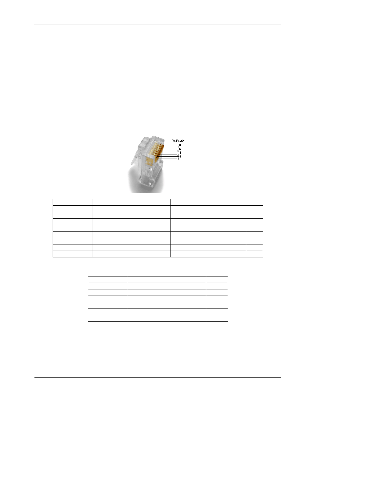
3.3.3 Serial
There are two serial interfaces on the GridRouter and they have RJ45 connectors referred to as Port 0
and Port 1. A mezzanine board attached to the power supply board defines whether the ports are RS232
or RS485. The RS232 board makes both Port 0 and Port 1 communicate via RS232. The RS485 board
turns Port 0 into an RS485 port and Port 1 into an RS232 port. The RS485 board has 3 jumpers which
control whether the card is half-duplex or full-duplex. If all of the jumpers are installed then the board is in
half-duplex mode. If none of the jumpers are installed then the board is in full-duplex mode. The pin
definitions for both RS232 and RS485 ports are shown below.
RJ45 Pin No. Signal Description Abbr. DTE (GridRouter) DCE
1 DCE Ready DSR In Out
2 Received Line Signal Detector DCD In Out
3 DTE Ready DTR Out In
4 Signal Ground SG
5 Received Data RxD In Out
6 Transmitted Data TxD Out In
7 Clear To Send CTS In Out
8 Request To Send RTS Out In
Table 3-1: RS232 Port Pinout
RJ45 Pin No. Signal Description Abbr.
1 VISO PWR
2 N/C
3 N/C
4 Shield Ground GND
5 Transmit + (TXP) RxD
6 Receive – (RXN) TxD
7 Transmit – (TXN) CTS
8 Receive + (RXP) RTS
Table 3-2: RS485 Port Pinout
12
Page 13

GridRouter™ User Guide
3.4 Mounting Options
The GridRouter has several different mounting options for a variety of environments. Contact your
SmartSynch sales representative for information on available mounting hardware.
Note: SmartSynch is not responsible for damages incurred by unsecured mounting hardware.
13
Page 14

GridRouter™ User Guide
4 Installing
4.1 Preliminary Inspections
The GridRouter is calibrated and tested at the factory and is ready for installation. Before installing and
applying power to the product, a quick inspection of the GridRouter is recommended to ensure there is no
damage to the GridRouter, which could possibly occur during shipping. Physical damage to the
GridRouter indicates potential damage to the inside of the GridRouter. Do not connect power to a
GridRouter that is suspected of having internal damage. Contact your SmartSynch technical support
representative if you suspect your GridRouter is damaged.
4.2 Installation Process
The SmartSynch GridRouter contains a cellular communications device. When the device is powered up
for the first time it will try to configure itself. The configuration process includes provisioning the modem
on the network, updating its hostname on the DNS server, and sending traps to an SNMP server.
4.2.1 Typical Installation Scenarios
On average, a technician will need 10 minutes to verify if a device has coverage. The GridRouter first
needs to be mounted correctly. Next, make sure that the power switch is in the OFF position (right) and
then attach the power connector. Wait until the battery LED illuminates before flipping the power switch to
the ON position (left). This could take up to 5 minutes.
The status LED will turn solid orange for approximately 120 seconds while the system is performing lowlevel setup for the first time. Once the high-level setup begins, the status LED will begin blinking orange
for approximately 60 seconds until the system is done with setup at which time the status LED will begin
blinking green.
The WAN LED for the modem will turn solid green when power is applied to the modem and it will begin
blinking green once the modem begins dialing out. If the modem is not provisioned, it will first try and
download the preferred roaming list (PRL) from the carrier before connecting to the internet. Once the
PRL successfully updates, the SGR will try and connect the modem to the internet and then try and
update its DNS entry in the specified DNS server. The DDNS LED will turn solid green once the DDNS
successfully completes. At this point, the GridRouter is fully operational.
4.2.1.1 Serial Device
Connect the serial cable between the end device and one of the serial ports on the GridRouter.
4.2.1.2 Ethernet Device
Connect an Ethernet cable between the end device and the GridRouter.
14
Page 15

GridRouter™ User Guide
5 Provisioning the GridRouter
The provisioning processes must complete to ensure that the GridRouter can receive remote
communication.
5.1 Cellular Modem
GSM modems have SIM cards and can be activated and provisioned through the cellular carrier without
any interaction from the GridRouter. CDMA modems must be activated by the carrier and then
provisioned by the GridRouter, done by dialing a phone number. This provisioning process for CDMA
modems is necessary for downloading and updating the Preferred Roaming List (PRL). The GridRouter
queries the modem routinely and updates the PRL when necessary.
5.2 Dynamic DNS (optional)
If the GridRouter modem has a dynamic IP address, it is recommended to setup dynamic DNS so that
communication can be initiated remotely. The default hostname for the GridRouter is based upon its 10digit serial number: sgr{serial#}. An example hostname is sgr3509f00001. The default DNS server
hostname is dyndns.org.
An example DNS setup with www.dyndns.com uses a hostname of “sgr3509f00001.dyndns.org” and a
DNS server address of “update.dyndns.org”.
15
Page 16

GridRouter™ User Guide
6 Configuration
6.1 Explanation of the UCI
The UCI (Universal Configuration Interface) is a collection of text files that contains the configuration for
the processes on the GridRouter. These settings can be altered through the web-based utility (HTTPS),
SSH, and the serial console.
16
Page 17
GridRouter™ User Guide
6.2 Web Interface
ATTENTION – Windows XP and Internet Explorer users
The default GridRouter SSL cipher is set to AES with 128-bit encryption. This level of security is not
supported by Internet Explorer (IE) when used on Windows XP. It is recommended to use Firefox or
Opera when using Windows XP or to use Windows Vista/7. The GridRouter is capable of being
configured (pre-deployment or over SSH) to use a lesser form of encryption so that IE can be used on
Windows XP.
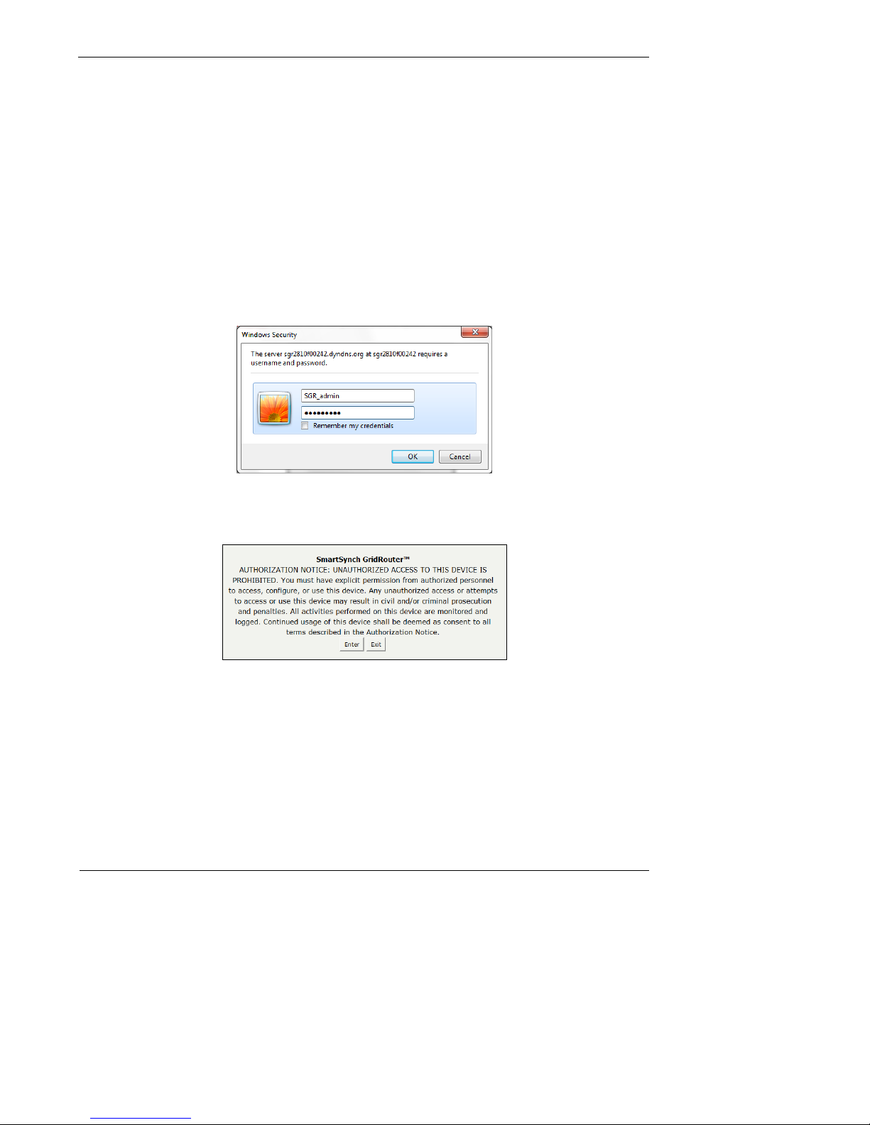
The web-based utility provides the ability to change the configuration settings on the GridRouter. You can
access the utility via a web browser on a computer connected to the GridRouter’s Ethernet port with the
default IP address, “https://192.168.0.254”, or over-the-air using the hostname or modem IP address.
The first time you open the web-based utility use the default user name “SGR_admin” and the default
password “admin_SGR“. (You can set a new password on the System > Password screen.) Click “OK“ to
continue.
Figure 6-1: Password Screen
The first time that you open the web-based utility on a given browser you will be forced to accept the
security banner by clicking “Enter”.
Figure 6-2: Security Banner
It is also worth noting that every screen in the web-based utility contains a common header and footer.
The header contains the firmware version, host name, uptime, date, time, and load. The footer contains
three links: “Apply Changes & Reboot”, “Clear Changes”, and “Review Changes”.
Pages that alter the GridRouter’s configuration all have a ”Save” button. The save button must be clicked
to temporarily write the files into RAM. The changes to the configuration can be reviewed by clicking the
”Review Changes” button and they can be committed to flash by pressing the ”Apply Changes &
Reboot” button.
17
Page 18

GridRouter™ User Guide
Figure 6-3: Review Changes
The following sections detail each page in the web-based utility.
6.2.1 Info
6.2.1.1 System
The first screen that appears is the System information screen. The firmware version, Ethernet MAC
address, and username are all displayed here.
Figure 6-4: Info > System
6.2.1.2 Devices
The Info > Devices screen will display information about the devices directly connected to the system.
Devices connected to each of the four FRU slots, the USB header, and the Ethernet connector will be
displayed. In addition, the settings of the serial ports and whether Serial Passthrough or Serial PPP is
running on each port will be displayed.
Figure 6-5: Info > Devices
18
Page 19
GridRouter™ User Guide
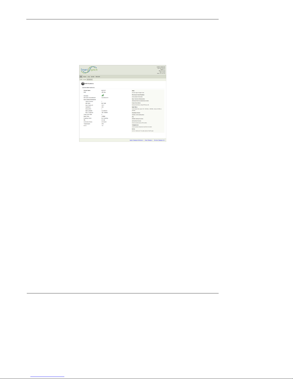
6.2.1.3 WAN Statistics
The Info > WAN Statistics screen will display information queried from the cellular modem. Typical
information found here includes received signal strength (dbm and bars), modem temperature, and
network status.
This page will display slightly different information depending on the type of modem type; whether HSPA
or EVDO.
Figure 6-6: Info > WAN Statistics
19
Page 20

GridRouter™ User Guide
6.2.2 Status
6.2.2.1 System
The Status > System screen shows RAM usage, number of tracked connections, and space available on
mounted file systems.
Figure 6-7: Status > System
RAM Usage
This is the current RAM usage. The amount free represents how much the applications have available.
Tracked Connections
This is the number of connections in the GridRouter conntrack table.
Mount Usage
This is the amount of space total and used on the file systems mounted on the GridRouter.
20
Page 21

GridRouter™ User Guide
6.2.2.2 Processes
The System > Processes screen displays all programs and processes currently running on the
GridRouter. This page also contains the ability to send signals to a running process which can terminate
or alter the behavior of the process. Refreshing must be stopped before a signal can be sent to a
process. Sending a signal to a running process can result in a loss of communication or system
malfunction.
Figure 6-8: Status > Processes
21
Page 22

GridRouter™ User Guide
6.2.2.3 Interfaces
The Status > Interfaces screen displays all GridRouter interfaces and information about each one;
including MAC address, IP address, maximum transmission unit (MTU), amount of data transmitted and
received during the current session, and a list of DNS servers.
Figure 6-9: Status > Interfaces
6.2.2.4 DHCP Clients
The Status > DHCP Clients screen displays information about the DHCP clients and their leases. The
time left on the lease is displayed along with the name of the device, MAC address, and the IP address
assigned to the client.
Figure 6-10: Status > DHCP Clients
6.2.2.5 Data Usage
22
Page 23

GridRouter™ User Guide
Deleted:
The Status > Data Usage screen shows data traffic information for each interface configured in Network >
vnStat screen. The information here can be viewed over different periods of time with each button.
Figure 6-11: Status > Data Usage
Query: Shows today’s connection traffic.
Hours: Shows data traffic by hour over the last 24 hours.
Days: Shows data traffic by day over the last week.
Weeks: Shows data traffic by week over the last month.
Months: Shows data traffic by month over the last year.
Note: While this is a very good estimate, the traffic amount displayed can be lower than the actual if the
GridRouter is not power-cycled cleanly. The traffic can be off by the amount of traffic since the last clean
reboot or power cycle in this case. To avoid this problem, use the clean power off method described in
section 3.3.1 of this document.
3.2.1
23
Page 24

GridRouter™ User Guide
6.2.2.6 Netstat
The Status > Netstat screen shows networking information for the GridRouter including physical
connections, the main routing table, listening ports, and active connections.
Figure 6-12: Status > Netstat
24
Page 25

GridRouter™ User Guide
6.2.2.7 Hardware
The Status > Hardware screen shows the current detected temperature at each FRU slot, temperature
limit information per device, and the ambient temperature of the power board. The system voltages at
various points on the board are also displayed along with all USB devices connected to the system and
any mounted memory devices.
Figure 6-13: Status > Hardware
Temperatures and Limits
The hysteresis values are used when FRUs start to return to the normal temperature range. The high
limit represents the upper temperature at which the FRU will be powered off until the temperature drops
to (High Limit - High Hysteresis). The heater limit represents the temperature at which the heater will start
warming the FRU until the temperature increases to (Heater Limit + Heater Hysteresis). The low limit is
the lower temperature at which the FRU will be powered off until the temperature increases to (Low Limit
+ Low Hysteresis).
Power board: Sensor located on the power board and represents the ambient temperature inside the
box.
FRU#: Sensor located beneath the FRU slot and represents an estimation of the FRU temperature.
System Voltages
The voltages at various points along the board are displayed including system voltage, USB voltage, and
voltages across multiple super capacitors.
25
Page 26

GridRouter™ User Guide
6.2.2.8 Diagnostics
The Status > Diagnostics screen contains several tools that may be useful when troubleshooting.
Figure 6-14: Status > Diagnostics
LED Utilities
Allows all LEDs on the GridRouter to be enabled/disabled remotely or set for a specific amount of time.
Note: A system event such as a door open event will override the settings here. After the timed
command completes or a system event occurs the LEDs will return to the default system state.
Network Utilities
The ping tool is used to test whether a particular host is reachable across an IP network from the
GridRouter. The traceroute tool is used to determine the route taken by packets across an IP network.
26
Page 27

GridRouter™ User Guide
6.2.3 Log
The GridRouter contains a logging application that all processes can direct their messages towards.
These messages can be configured to either be temporarily stored in RAM or persist in nonvolatile
memory. Along with storing informational messages, the GridRouter has the ability to capture all data
across a given interface to help with troubleshooting connectivity issues.
27
Page 28

GridRouter™ User Guide
6.2.3.1 System Settings
The Log > System Settings screen provides the ability to view/change the system logging configuration
values.
Figure 6-15: Log > System Settings
Remote Syslog
The Syslog remote logging functionality can be enabled by entering a server IP address.
Server IP Address: Specifies the IP Address for the remote logs to reside.
Server Port: Specifies the port on Server IP Address that has the syslog application listening.
Local Log
The local log file is used by all of the GridRouter’s applications and is known as the main log file.
Log Type: Specifies whether your log file will be stored in a memory circular buffer (“Circular“) or in a file
(File). If you require that your log persist across reboots, select “File“, but constantly writing data could
reduce the life of the onboard flash chip. It is highly recommended that the File log type only be used to
temporarily aid in diagnosing issues.
Log File: Specifies the path and name of your log file.
Log Size: Specifies the size of your log in kilobytes. Be careful with the size of the circular buffer as it is
taken from your main memory.
Save Tail of Syslog on Reboot: Enables the tail end of the syslog to be saved before shutdown. This is
useful for determining the cause of unexpected reboots.
Save Tail Length: Specifies the number of lines of the syslog to save on shutdown.
Save Tail File: Specifies the file location to write the tail of syslog.
Kernel Log
28
Page 29

GridRouter™ User Guide
Deleted:
Message Priority: Logs messages up to the defined priority.
Ring Buffer Size: Specifies the size of space the kernel will reserve for messages in memory.
Boot Time Log
This log file contains messages that occur on boot-up.
Backup Boot Time Messages: Specifies whether your boot time messages will be saved to a file for
later reference.
Backup File: Specifies the path and name of your boot time log file.
Compress Backup: Specifies whether the boot time log file will be compressed.
6.2.3.2 System Downloads
The Log > System Downloads screen provides the ability to download the system log files in zip
(Windows) or gzip (Unix) format. Regardless of where the system messages are stored (memory or
flash), they can be compressed and downloaded. The estimated compressed file size is shown so the
user can be aware of the data burden that will be incurred by clicking to download. In addition to the full
system log, the tail section of the system log from the last shutdown can also be downloaded.
Figure 6-36: Log > System Downloads
29
1
Page 30

GridRouter™ User Guide
Deleted:
Deleted:
6.2.3.3 Serial PPP Settings
The Log > Serial PPP Settings screen allows the data from a serial PPP session to be logged. Enabling
logging on an instance of Serial PPP will make a log available for download.
Figure 6-47: Log > Serial PPP Settings
serppp Log: Specifies whether logging is enabled or disabled.
serppp Log File: Specifies the path and name of the log file.
6.2.3.4 Serial PPP Downloads
The Log > Serial PPP Downloads screen provides two download formats for each instance’s log. The
text format is a standard text document that can be opened in any editor. The pcap format is a packet
capture file that can be opened with most packet sniffing programs including Wireshark. This page also
contains a link to clear out the old log files.
Figure 6-58: Log > Serial PPP Downloads
1
1
30
Page 31

GridRouter™ User Guide
6.2.3.5 Serial Passthrough Settings
The Log > Serial Passthrough Settings screen allows debug logging of serial passthrough to be
configured on the system. TCP data, serial data, or both can be logged for each instance of serial
passthrough. Both types of data will be logged to the same file.
Figure 6-196: Log > Serial Passthrough Settings
Log Serial Packets: Specifies whether logging serial data is enabled or disabled.
Log TCP Packets: Specifies whether logging TCP data is enabled or disabled.
Log File: Specifies the path and name of the log file.
6.2.3.6 Serial Passthrough Downloads
The Log > Serial Passthrough Downloads screen provides a means to download the text-based log file
outputted by the serpass application. Depending on the settings this file may contain serial data, TCP
data, or both. This page also contains a link to clear out the old log file.
Figure 6-20: Log > Serial Passthrough Downloads
31
Page 32

GridRouter™ User Guide
6.2.3.7 Interface Settings
The Log > Interface Settings screen allows debug logging of each interface to be configured on the
system.
Figure 6-21: Log > Interface Settings
Logging Status
Displays the current status of the logging processes for each interface. Possible values are
“Disabled“,“Enabled“, and “Not Running“. “Not Running“ implies that the logging has been enabled but
is stopped.
Logging Controls
Controls: The “Start Logging“ button starts all enabled interface logging processes. The new logs will
clear the previous logs. The “Stop Logging“ button will stop all currently running interface logging
processes and save the backup of the current logs if enabled.
{interface} Log
{interface} Log: Specifies whether or not the interface is to be logged.
Log Level: Specifies the amount of information to display in the log. Possible values include
“Quiet“,“Normal“,“Verbose“,“Very Verbose“, and “Very Very Verbose“.
Log File: Specifies the path of the log file to be saved. If using the /tmp or /var directories, the log will not
persist across reboots.
Max Log Size (MB): Specifies the maximum size of the log file. Once the file reaches this size, the
current file will be closed and a new one will be opened.
Number of Logs to Create: Specifies the limit of new log files to be created once one reaches the
maximum size. Once this limit is reached, the oldest file is removed creating a rotating buffer.
Enable Backup of Logs: Specifies whether or not the log files should be saved elsewhere in the event of
a reboot or an interface restart.
Backup Location: Specifies the directory where the current log files should be placed in the event of a
reboot or an interface restart.
32
Page 33

GridRouter™ User Guide
6.2.3.8 Interface Downloads
The Log > Interface Downloads screen provides the ability to download log files that captured all data
from a specific interface (wan, lan, etc.).
Figure 6-22: Log > Interface Downloads
Select Log Format
Log Download Format: Specifies the format of all downloads on the page. Packet Capture formatting
will create a file that can be opened by Wireshark. Text formatting is in a human readable form that can
be opened with any standard text editor.
Download {interface} Log
Current Log: Button to download the log that is currently being written.
Backup Log: Button to download the last log file saved when logging was stopped.
33
Page 34

GridRouter™ User Guide
6.2.4 System
6.2.4.1 Settings
The System > Settings screen allows for configuration of GridRouter’s time zone and NTP servers.
Figure 6-23: System > Settings
Time Settings
Timezone: Specifies the time zone for the GridRouter which is mainly used for accurate time stamps in
the log files. The drop down box includes all time zones.
POSIX TZ String: [Read-only] Specifies the POSIX TZ string for reference.
Primary NTP Server: Specifies the URL to the primary NTP server.
Secondary NTP Server: Specifies the URL to the secondary NTP server.
34
Page 35

GridRouter™ User Guide
Deleted:
6.2.4.2 Access Control
The System > Access Control screen allows the administrator to create new users on the system and set
up which web interface pages that they may view.
Figure 6-74: System > Access Control
Add New User
A generic user can be created in this form. Once created the specific settings can be altered on the
subsequent forms.
Username: Specifies a user’s name.
Password: Specifies the user’s password.
Current Users
A list of the current users on the system along with various configuration settings.
User shell: Specifies whether or not the user is permitted to login to the shell over serial or SSH.
Current days since epoch: Specifies the number of days since January 1, 1970.
Password expiration: Specifies the number of days from today that the password will expire.
Password changed: Specifies the days since epoch that the password was last changed. Setting this to
0 will force a password change on next login.
Min. password change: Specifies the minimum number of days required between user password
changes.
Max. password change: Specifies the maximum number of days required between user password
changes.
Warning time: Specifies the number of days before a password expires that a user is warned about the
expiring password.
35
2
Page 36

GridRouter™ User Guide
Deleted:
Expire inactive: Specifies the number of days after a password expires that an account is disabled.
Setting this blank causes the account not to expire after the password expires.
Account expiration: Specifies the number of days from epoch that the account will be disabled. Setting
this blank causes the account not to expire.
Web Interface Permissions
A list of all users and all web pages and whether or not a user is allowed to access that page. Note: The
users will currently have write access to any page that they are allowed to view.
6.2.4.3 Password
The System > Password screen allows you to change the user password. The default administration
password is “admin_SGR“.
Figure 6-85: System > Password
2
36
Page 37

GridRouter™ User Guide
Deleted:
6.2.4.4 Packages
The System > Packages screen provides the means to view, install, and uninstall packages from the
GridRouter.
A GridRouter package is computer software packaged in an archive format (*.ipk) to be installed by the
package management system (opkg). Each package generally contains a specific application or service.
Most GridRouter firmware upgrades will be presented in package form.
Figure 6-96: System > Packages
Add Repository
A repository is a server that contains a list of packages that can be installed on your GridRouter. Adding a
new server allows you to list packages here that are not shown by default.
Repo. Name: Specifies a descriptive name for the repository.
Repo. URL: Specifies the URL that points to the directory in the repository that contains the Packages
file. The Packages file lists all the available packages, their dependencies, descriptions, and md5 sums.
An example value here is ftp://user:password@192.168.10.100/.
Install Package from URL
Normally you install a package by clicking the install link in the list of packages below. However, you can
install a package not listed in the known repositories here.
URL of Package: The URL that points to the package to be installed.
Installed Packages
This is a list of packages that are currently installed on the GridRouter. The “uninstall“ link can be used to
uninstall an individual package.
37
2
Page 38

GridRouter™ User Guide
Deleted:
Available Packages
This is a list of packages that are not currently installed on the GridRouter. The “install“ link can be used
to install an individual package.
6.2.4.5 SNMP
The System > SNMP screen allows for configuration of the GridRouter’s SNMP settings. The GridRouter
sends in SNMP traps when certain conditions occur and they are sent to the server specified on this
page.
Figure 6-107: System > SNMP
SNMP Trap Settings
The SNMP trap server settings on the GridRouter.
Server: Specifies the IP address or host name of the SNMP trap server.
Port: Specifies the port number on the server that the trap will be sent to.
Protocol: Select the protocol used for this rule, either “TCP“ or “UDP“.
Acknowledge: Specifies whether the GridRouter requires an acknowledgement from the server. Trap
acknowledgements ensure that the server correctly receives traps. If set to “no“, the trap will still be sent
to the server but failures cannot be detected. If set to “yes“, any unacknowledged traps will be queued
and retried later.
Community: Specifies the community string.
2
38
Page 39

GridRouter™ User Guide
Deleted:
6.2.4.6 Backup & Restore
The System > Backup & Restore screen provides the ability to download current GridRouter configuration
and upload new configuration.
Figure 6-118: System > Backup & Restore
Backup Configuration
The GridRouter’s entire configuration is stored in text files. These files can be compressed into a single
file and downloaded here.
Name this configuration: Specifies the name of the configuration. This is not the filename of the zip file,
but rather, it is the value that will be displayed when restoring the configuration.
Restore Configuration
A previously downloaded configuration file can be uploaded to the GridRouter to restore the configuration.
Saved config.zip file: Specifies the path on the remote computer to the previously downloaded
configuration file (e.g. C:\Users\Administrator\Desktop\config.zip).
6.2.4.7 Reboot
The System > Reboot screen is used to safely reboot the GridRouter remotely.
2
39
Page 40

GridRouter™ User Guide
6.2.5 Network
6.2.5.1 Networks
The Network > Networks screen allows you to configure the GridRouter’s network settings such as IP
address, netmask, and gateway.
Figure 6-2912: Network > Networks
Network Configuration
Specific options for each network interface.
Connection Type: Specifies the type of connection; “Disabled“,“DHCP“, or “Static IP“.
Type: Select whether the network is bridged or not.
MAC Address: Specifies the MAC address of the network.
IP Address: Specifies the IP address of the network.
Netmask: Specifies the mask used to divide an IP address into subnets.
Default Gateway: Specifies the IP address of the router that network traffic should be sent when the
traffic is not on the same subnet as the sending device.
Add Network: Specifies the name of the interface to be created when the “Add Network” button is
pressed.
40
Page 41

GridRouter™ User Guide
Deleted:
6.2.5.2 Interfaces
The Network > Interfaces screen allows interfaces (i.e. eth0, ppp0, wlan0) to be mapped to networks (i.e.
lan, wan, wlan) on the system. By default, eth0 is the lan and ppp0 is the wan.
Figure 6-130: Network > Interfaces
3
41
Page 42

GridRouter™ User Guide
6.2.5.3 Wi-Fi
6.3 The Network > Wi-Fi screen allows a supported 802.11 wireless
card to be configured. Detailed instructions on how to enable the
Wi-Fi card can be found in the “Examples” section under “
Formatted: Bullets and Numbering
42
Page 43

GridRouter™ User Guide
Deleted:
Deleted:
Enable as Wi-Fi Access Point”.
Figure 6-141: Network > Interfaces
Wireless Adapter radio Configuration
To change the physical aspects of the wireless card, edit these options.
Radio: Turns broadcasting on or off for the device.
Channel: Specifies the physical channel the radio is broadcasting on.
Wireless Distance: Used to set the transmit power of the device. [Unused]
Wireless Virtual Adaptor Configuration
To change the software settings for the wireless card, edit these options.
Network: Affiliates a wireless card with a network on the system. This value will often be set to “wlan” or
“wifi” depending on the name of the interface that was added.
Mode: Sets the wireless card to be an “Access Point”, “Client”, or “Ad Hoc”. Currently only “Access
Point” is supported.
AP Isolation: This isolates all wireless devices on the GridRouter network from each other. [Unused].
RTS: Request to send threshold.
Fragmentation: Fragmentation threshold.
ESSID: Specifies the broadcasted name of the Access Point.
Encryption Type: Encryption type used.
Point
Enable as Wi-Fi Access
3
43
Page 44

GridRouter™ User Guide
Deleted:
6.3.1.1 Firewall
The Network > Firewall screen allows you to customize port services for common applications. When
users send these types of requests to your network via the Internet, the GridRouter will deny or allow
those requests and, if enabled, forward them to the appropriate devices. Before using forwarding you
should assign static IP address to the designated devices. Refer to the DHCP page, section 6.2.5.6, for
more information on assigning static IP addresses.
Figure 6-152: Network > Firewall
Incoming Ports
Incoming ports are used to allow access to the GridRouter itself, not devices connected to the
GridRouter. An example would be querying SNMP information from the GridRouter. To allow/deny a
single port, enter the information on each line for the criteria required. The IP address “0.0.0.0” can be
used to denote any address.
Name: Specifies the name to give the rule. The name should not have any spaces.
Protocol: Select the protocol used for this rule, either “TCP“,“UDP“,“Both“, or “ICMP“.
Source IP: Specifies the IP address the request is coming from.
Destination IP: Specifies the IP address that the request is going to.
Port: Specifies the external port number. Multiple ports can be specified by using a hyphen and commas:
“9000-9009,9011,9014-9016”.
Port Forwarding
Port forwarding is used to allow access to devices connected to the GridRouter. An example would be
accessing a device connected to the Ethernet of the GridRouter. To forward a single port, enter the
information on each line for the criteria required. The IP address “0.0.0.0” can be used to denote any
address.
Name: Specifies the name to give the rule. The name should not have any spaces.
Protocol: Select the protocol used for this rule, either “TCP“ or “UDP“, or “Both“.
Source IP: Specifies the IP address the request is coming from.
Destination Port: Specifies the external port number. Multiple ports can be specified using a hyphen and
commas: ” 9000-9009,9011,9014-9016”.
To IP Address: Specifies the local IP address that should receive the requests.
3
44
Page 45

GridRouter™ User Guide
Deleted:
To Port: Specifies the internal port number. This value should normally be blank so that a 1 to 1 port
forward can occur. If, however, a value is specified here then any port(s) listed under “Destination Port”
will be redirected to this single port. There is currently not a way to forward ports 1-9 to 21-29 in a single
rule.
MAC Address Filtering
Name: Specifies the name of the firewall rule.
MAC Address: Specifies the address to explicitly allow. All other MAC address on the selected interface
will be rejected.
Interface: Specifies the name of the interface on which to allow the MAC address.
6.3.1.2 vnStat
The Network > vnStat screen is used to monitor network traffic burdens for the selected interface(s).
Figure 6-163: Network > vnStat
vnStat Settings
Polling delay in minutes: Specifies the number of minutes between successive polls. This value should
be selected low enough as to not be able to transfer 4GB of data between polls. If the wrap around
occurs the results will not be accurate.
Database save directory: Specifies the directory to save the logs in the event of a reset. This value
should be in non-volatile memory.
Monitored Interfaces
Interface: Specifies the interface to be monitored.
Nickname: Specifies the user friendly name to display when presenting data usage reports.
Enabled: Specifies whether or not to monitor the selected interface.
45
3
Page 46

GridRouter™ User Guide
Deleted:
6.3.1.3 DHCP
The Network > DHCP screen allows you to configure the GridRouter’s Dynamic Host Configuration
Protocol (DHCP) server function. The GridRouter can be used as a DHCP server which automatically
assigns an IP address to each device on your network.
Figure 6-174: Network > DHCP
LAN DHCP
The DHCP settings for devices connected to the GridRouter through the Ethernet connector.
DHCP: DHCP is enabled by factory default. If a DHCP server is not desired, then select “Off“.
Start: Specifies the 4th octet of the IP address to start issuing IP addresses. For example, the default IP
address is “192.168.0.254“, so this start value must be less than 253 (192.168.0.253). The default Start
value is “1“ (192.168.0.1).
Limit: Specifies the maximum number of devices that the DHCP server will assign IP addresses to.
Lease Time: Specifies the number minutes a network user will be allowed connection to the GridRouter
with their current dynamic IP address.
Static IP Addresses
The DHCP server uses the matching IP address instead of allocating a new one from the pool for any
MAC address listed in this file.
Name: Specifies the name of the rule or end device.
MAC Address: Specifies the MAC address of the device that will be receiving the static IP address.
IP Address: Specifies the IP Address to assign to device with the specified MAC Address.
Device Type: Specifies the type of device receiving an IP address. This value should be “Generic“
unless connected to an Echelon Ethernet Data Concentrator (DC).
The Echelon DC requires that its local IP address changes when the GridRouter’s WAN address changes
to ensure that the DC will call back into the NES server. The least time should be around 5 minutes to
ensure that the DC will call back within 5 minutes of the WAN address changing. The local IP address
assigned to the DC will cycle through the range of address specified by the Start and End IP Addresses
each time that the WAN address changes. The suggested range is 10 addresses and 2 is the minimum.
Port forwarding firewall rules that have a “Static IP Rule” set to something other than “None” will
automatically be adjusted to match the DC’s address.
46
3
Page 47

GridRouter™ User Guide
Deleted:
Echelon DC – Start IP Address: Specifies the beginning of the IP address range to assign to the DC.
Echelon DC – End IP Address: Specifies the end of the IP address range to assign to the DC.
Echelon DC – Lease Time: Specifies the number of minutes the DC will be allowed to use that local IP
address.
Active DHCP Leases
A list of the currently active DHCP leases.
6.3.1.4 Hosts
The Network > Hosts screen is used to configure the hosts file on the GridRouter. When accessing a
device by name, the GridRouter’s networking system attempts to locate the name within the hosts file
before accessing the DNS server.
Figure 6-185: Network > Hosts
Host Names
Host Name: Specifies the name of the device.
IP Address: Specifies the IP address of the device with the specified host name.
3
47
Page 48

GridRouter™ User Guide
Deleted:
6.3.1.5 Routes
The Network > Routes screen allows you to configure the routing tables on the GridRouter. IP Routing is
an umbrella term for the set of protocols that determine the path that data follows to travel across multiple
networks from its source to its destination. These protocols enable the GridRouter to build up a
forwarding table that correlates the final destinations with the next hop addresses.
Figure 6-196: Network > Routes
Configured IPv4 Static Routes
Destination: Specifies either an IP address or host name for the network or host.
Gateway: Specifies either an IP address or host name for the gateway or GridRouter to use when
forwarding.
Netmask: Specifies a subnet mask to be associated with this route entry.
Metric: Assigns an integer cost metric (range from 1 through 9,999) to be used in calculating the fastest,
most reliable, and/or least expensive routes.
Use With: Specifies the interface to be used for the route.
Name: Specifies the name of the route.
3
48
Page 49

GridRouter™ User Guide
Deleted:
Deleted:
6.3.1.6 DynDNS
The Network > DynDNS screen allows you to configure the Dynamic Domain Name System (DDNS)
feature that allows you to assign a fixed host and domain name to a dynamic Internet IP Address. If the
onboard modem has a static IP address then this feature can be disabled.
Figure 6-207: Network > DynDNS
DynDNS
Dynamic DNS Update: Default value is “Enable“.
Host Name: Specifies the DDNS URL assigned by the DDNS service. Default value is
“sgr{serial#}.dyndns.org“.
Server: Specifies the IP address or host name of the nameserver. Default value is
“update.dyndns.com“.
Port: Default value is “53“.
Zone: Specifies the DNS domain to be updated. Default value is “sgr{serial#}.dyndns.org“.
Key Name: Specifies the name of the key used in the TSIG protocol. This value will need to be provided
by the DNS server.
Key HMAC: Specifies the base64 encoded shared secret used in the TSIG protocol. This value will need
to be provided by the DNS server.
Delete Previous Entry: Some DNS servers only allow updates (select “No“), but others allow you to
delete an entry and re-add it (select “Yes“).
6.3.1.7 Tweaks
The Network > Tweaks screen allows you to set default timeout and connection values for the system.
3
Figure 6-218: Network > Tweaks
49
3
Page 50

GridRouter™ User Guide
6.3.1.8 IPSEC
Configuration of IPSEC is beyond the scope of this document. Please refer to the GridRouter IPSEC
Configuration User Guide for information on how to use and configure the IPSEC functionality of the
GridRouter.
Figure 6-39: Network > IPSEC
50
Page 51

GridRouter™ User Guide
Deleted:
6.3.1.9 Serial PPP
Serial PPP is an application that acts as a modem emulator and provides a PPP connection to a device
connected serially to the GridRouter. Any device that would connect directly to a modem and issue AT
commands should be able to connect to the GridRouter and access the same network as the GridRouter
(whether public to the Internet or a private network). Some serial devices alert a head-end server
whenever their IP address changes, so the GridRouter has the capability to reset the serial PPP
connection whenever its WAN IP address changes. The GridRouter toggles between a primary and a
secondary local IP address when assigning one to the serial PPP device.
Figure 6-220: Network > Serial PPP
Configuration
Enabled: Default value is “Disable“.
Baudrate: Specifies the number of symbols per second transferred.
Data bits: Specifies the actual number of data bits sent in a character frame.
Parity: Additional error checking on serial data transfer.
Stop bits: Specifies the number of stop bits in a serial character frame.
Device: Specifies the physical RJ45 serial connector on the GridRouter. “Serial0“ represents “Port 0” on
the board’s silk screen. “Serial1“ represents “Port 1”.
Primary Local IP Address: Specifies the primary IP address to be given to the device connected serially
to the GridRouter.
Update Local IP: Specifies whether or not to force the GridRouter to toggle the local IP address between
primary and secondary each time the WAN IP address changes.
Secondary Local IP Address: Specifies the secondary IP address to be given to the device connected
serially to the GridRouter.
Verify Update Ack: Specifies whether or not to toggle the local IP address if incoming traffic on the port
is not seen within the ‘Update Ack Timeout’ period.
Update Ack Timeout: Specifies the amount of time in seconds to wait for acknowledgement traffic before
51
4
Page 52

GridRouter™ User Guide
reverting to the alternate local IP address.
Port Forwarding
To forward a single port, enter the information on each line for the criteria required. It is important to
make the serial PPP firewall changes in this form because the rules are auto named and will change the
destination IP address based upon which (primary or secondary) local IP address is currently being used
for the PPP session.
Name: Specifies the name to give the rule. This is auto generated.
Protocol: Select the protocol used for this rule, either “TCP“ or “UDP“, or “Both“.
Source IP: Specifies the IP address the request is coming from.
Destination Port: Specifies the external port number.
To Port: Specifies the internal port number.
52
Page 53

GridRouter™ User Guide
Deleted:
6.3.1.10 Serial Passthrough
The Network > Serial Passthough screen allows you to change the configuration for the passthrough
application that provides a gateway between a conventional RS232/RS485 serial interface and a TCP
socket.
Figure 6-231: Network > Serial Passthrough
Enabled: Default value is “Disable“.
Physical: Specifies the physical interface as either “RS232“ or “RS485“. This value does not change the
physical interface but rather, it defines the actual hardware configuration that is present. You must be
certain of the hardware configuration before making this change. Note: ‘serial0’ is the only device capable
of RS485 currently.
Duplex: Specifies the RS485 duplex as either “Half“ or “Full“. This value does not change the physical
interface but rather, it defines the actual hardware configuration that is present. There is a jumper on the
RS485 daughterboard that is responsible for this value. Refer to section 3.2.3 for more information.
Baudrate: Specifies the number of symbols per second transferred.
Effective Baudrate: Disabled by default (“0“) but can be used to slow the transmission of data as the
receiver cannot keep up with the speed of the transmitter.
Data bits: Specifies the actual number of data bits sent in a character frame.
Parity: Additional error checking on serial data transfer.
Stop bits: Specifies the number of stop bits in a serial character frame.
Device: Specifies the physical RJ45 serial connector on the GridRouter.
TCP Port: Specifies the TCP/IP port number.
TCP Buffer Timeout MS: Specifies the timeout in milliseconds for the TCP buffer to output flush.
TCP Buffer Size: Specifies the buffer size for TCP transmission.
TCP Idle Timeout: Specifies the number of seconds a TCP connection is allowed to remain idle before
the port is closed.
4
53
Page 54

GridRouter™ User Guide
7 Examples
7.1 Serial Passthrough to a Serial Device
The GridRouter can provide network connectivity to a device that only talks over serial (RS232/RS485).
A single TCP port can be mapped to a serial port such that all traffic sent or received from either one is
passed through to the other. For instance, a software application that traditionally connects to a serial
port (i.e. COM5), could connect to an IP address and a TCP port and communicate to the end device.
The steps required to enable serial passthrough on the GridRouter are as follows:
1. Attach a serial cable (generally null modem) between one of the GridRouter’s serial ports and the
device’s serial port.
2. Visit the web-based utility’s Network > Serial Passthrough screen.
3. Click the “Enable“ button on an instance of the serpass process (i.e. serpassA).
4. Enter the correct serial port settings (baudrate, data bits, parity, stop bits).
5. Enter the correct TCP settings (port and timeouts).
6. Click Save Changes and wait for the page to refresh.
7. Verify configuration values.
8. Click Apply Changes & Reboot.
Once the GridRouter reboots, the serpass process will be running and passing data between the
specified TCP port and the specified serial port.
Note: The GridRouter’s firewall will automatically allow incoming traffic on the specified TCP port for
serpass.
54
Page 55

GridRouter™ User Guide
7.2 Serial Data Concentrator to NES
When a serial Echelon Data Concentrator (DC) is connected directly to a modem it dials a number with an
AT command (i.e. “ATDT10001”). The modem will respond with “CONNECT” and then the Point-to-Point
Protocol (PPP) will be used to establish a direct connection between the DC and the Internet service
provider (ISP). The GridRouter acts as a modem emulator and will listen for the “ATDT” command before
responding with “CONNECT” and then initiating the PPP connection.
The DC will natively try and alert the head-end server (NES) whenever its IP address changes. Since the
DC is on the GridRouter’s local network (192.168.*.*), the DC’s IP address will normally stay the same, so
that the firewall rules can be the same. Therefore, the DC will never alert the NES server when the WAN
address of the GridRouter changes, leaving the DC without communication.
The GridRouter has the ability to change the local IP address of the DC when the WAN address changes
to force the DC to alert NES. A primary and a secondary IP address are toggled and assigned to the DC
and the firewall rules are automatically altered to match the DC’s address. To ensure that this toggling of
addresses is used on the DC, make sure to enable the ‘Update Local IP’ rule on the web interface.
The steps required to set up the GridRouter to connect to a Data Concentrator are as follows:
1. Attach a null modem serial cable between the Data Concentrator and a GridRouter serial port.
2. Visit the web-based utility’s Network > Serial PPP screen.
3. Click the Enable button on an instance of the serppp process.
4. Enter the correct serial port settings.
5. Enter both a primary and secondary local IP address to assign to the Data Concentrator.
6. Disable ‘Update Local IP’ if your GridRouter has a static IP address.
7. Add port forwarding rules so that the NES software can reach the Data Concentrator through the
GridRouter’s firewall.
Figure 7-1: Example Port Forwarding Rules for a DC
8. Click Save Changes. Wait for page refresh.
9. Verify configuration values.
10. Click Apply Changes & Reboot.
Once the GridRouter reboots, the serppp process will be running and the Data Concentrator will be ready
to go.
Note: Common communication ports for the Echelon Data Concentrator are 65432, 65400, and 22 (SSH).
55
Page 56

GridRouter™ User Guide
7.3 Ethernet Data Concentrator to NES
The Ethernet Data Concentrator (EDC) is slightly different than a “normal” Ethernet device. As with the
serial Data Concentrator, the EDC alerts the head-end server when its IP address changes. If the
GridRouter has a static WAN address then a static local address can be assigned to the EDC and
everything will work like a “normal” Ethernet device. If the GridRouter has a dynamic IP WAN IP address
then the GridRouter has to routinely alter the local IP address assigned to the EDC so that it will call into
the head-end server. The EDC must be set up for DHCP, else this will not work.
The GridRouter will statically assign an IP address to the EDC based upon its MAC address. The
leasetime is set to 5m so the EDC will request an IP frequently. If the GridRouter WAN address changes,
it will change the IP address assigned to the EDC.
The steps required to set up the GridRouter to connect to an EDC are as follows:
1. Attach an Ethernet cable (straight or crossover) between the EDC and the GridRouter’s Ethernet
port.
2. Visit the web-based utility’s Network > DHCP screen.
3. Create a Static IP address rule
a. Set the name (no spaces)
b. Enter the MAC address in the form aa:bb:cc:dd:ee:ff
c. Select a local IP address to assign to the EDC. Make sure it is on the same subnet as
the GridRouter.
d. Select “Echelon DC” as the Device Type.
e. Provide a Start IP Address. This should be the same as the IP address from above.
f. Provide an End IP Address that is roughly 10 addresses larger than the start. The range
can be as small as 2 but is recommended at 10.
g. Set the leasetime to something around 5 minutes. This is essentially the maximum
amount of time that the EDC will be waiting before it contacts the head-end server after a
WAN IP change.
4. Click Save Changes. Wait for page refresh.
5. Visit the web-based utility’s Network > Firewall screen.
6. Add Port Forwarding rules so that the NES software can reach the EDC through the GridRouter’s
firewall. Be sure to set the “Static IP Rule” equal to the name of the DHCP name provided earlier.
This value is in a drop down.
7. Click Save Changes. Wait for page refresh.
8. Click Apply Changes & Reboot.
56
Page 57

GridRouter™ User Guide
7.4 Enable as Wi-Fi Access Point
The Wi-Fi module must be installed before the GridRouter is powered up. The steps required to set up
the GridRouter to act as a Wi-Fi access point are as follows:
1. Visit the web-based utility’s Network > Networks screen.
2. At the bottom of the screen, enter "wlan" in the "Add Network" field and click the "Add Network"
button. The network name can be anything you want (i.e. “lan2”, “wifi”, etc.).
a. Change the wlan "Connection Type" to "Static IP".
b. Enter "192.168.x.254" as the "IP Address" where x is the FRU slot number the Wi-Fi
card is located in.
c. Enter "255.255.255.0" in the "Netmask" field.
d. Click the "Save Changes" button.
3. Visit the web-based utility’s Network > DHCP screen, select "wlan" and click the "Add DHCP"
button.
4. Click the "On" button for the "wlan DHCP" "DHCP" option
a. Add a "Start" value between 1 and 253 that will not overlap with an existing DHCP range
b. Add a "Limit" value that will not cause an overlap with an existing DHCP range
c. Add a "Lease Time" value
d. Click the "Save Changes" button.
5. Click the "Wi-Fi" submenu and select the "On" button for the "Radio"
a. Select the desired "Channel"
b. Ensure that "wlan" is selected for the "Network"
c. Ensure that "Access Point" is selected for the "Mode"
d. Set the "ESSID" field to the correct value
e. Set the "Encryption Type" to "WPA (PSK)"
f. Enter a valid password into the "WPA PSK" field
g. Click the "Save Changes" button.
6. Click the "Apply Changes & Reboot" link at the bottom of the page.
7. After the reboot the Wi-Fi will be operational. To ensure that the data usage values are accurate
please visit the web-based utility’s Network > Interfaces screen and set “Interface wlan0” to
“wlan”. Keep “Interface mon.wlan0” as “None”.
8. Click the “Save Changes” button.
9. Another reboot is required for data usage monitoring to be accurate but is not required for Wi-Fi
functionality.
Note: With the WN6601A module, single antenna configurations must use the “1” or left connector.
57
Page 58

GridRouter™ User Guide
Deleted:
8 Appendix A: Specifications
Ports Power, Ethernet, USB, PCIe Mini Card x4
LEDs Status, DDNS, Serial x2, Ethernet (Link, Activity),
Battery, PCIe Mini Card x4 (WWAN, WLAN, WPAN)
Main Board
Enclosure Nema4x
CPU Board (CPU) PowerPC (405EXr, 333 MHz)
Flash Onboard: 128MB
Optional: SD card FRU storage
DRAM 64MB or 256MB
Operating System OpenWRT 8.09 (Linux kernel 2.6.32.14)
Capacitor Storage Bank Up to 60 seconds
External Antennas Note: The WAN antenna can be configured as remote
with the purchase of the remote antenna kit. Contact
your SmartSynch sales representative for more
information.
WAN Antenna GSM, CDMA: 806-960 Mhz @ 1.4 dBi, 1710-1990
Mhz @ 4 dBi
LAN Antenna ZigBee: 2.4-2.5 Ghz @ 2.5
WiFi: 2.4-2.5 GHz @ 2.5
Electrical, Physical, and Environmental
Input Voltage 85-305 V AC, 50/60 Hz
9-30 V DC, 20 Watts
Dimensions (approx.) 8.74 in/22.2 cm length
9.13 in/23.2 cm width
3.9 in/10.0 cm depth
Weight (approx.) 1.5 lbs/0.7 kg
Operating Temp. -40 to +85°C
Note: Optional FRU cards maybe have different
temperature specifications.
Humidity Range 0% to 100% non-condensing
Regulatory & Industry Certifications
FCC Part 15 Class B
FCC Part 22
FCC Part 24
FCC Part 90
PTCRB Certification
ANSI C37.90.1 – 1989
ANSI C12.20 – 1998
AT&T Network Certification
Verizon Network Certification
Specifications are subject to change without notice.
Serial x2,
58
Page 59

GridRouter™ User Guide
9 Appendix B: SNMP Traps
The Simple Network Management Protocol (SNMP) is used by network management systems to
communicate with the GridRouter. An SNMP TRAP is a message that is initiated by the GridRouter and
sent to the network management system, generally to indicate some sort of alarm (e.g. power failure).
Refer to the “SNMP_MIB_OID_information” document for more information on GridRouter SNMP traps.
59
Page 60

GridRouter™ User Guide
10 Appendix C: Requirements and Compliance
The Smart GridRouter is compliant with all applicable Federal Communications Commission (FCC) and
Industry Canada (IC) requirements.
10.1 FCC Grant Statement
The antennas used for this transmitter must be installed to provide a minimum separation distance of 20
cm from all persons, and must not be co-located or operate in conjunction with any other antenna or
transmitter.
10.2 Compliance Statement (Part 15.19)
The Smart GridRouter complies with Part 15 of the FCC Rules and with RSS-210 of Industry Canada.
Operation is subject to the following two conditions:
1. This device may not cause harmful interference, and
2. This device must accept any interference received, including interference that may cause
undesired operation.
10.3 Warning (Part 15.21)
Changes or modifications not expressly approved by SmartSynch, Inc. could void the user’s authority to
operate the equipment.
10.4 RF Radiation Safety Guidelines per Part 2 of FCC Rules and
Regulations
The device should be installed in a location where there will be a separation greater than 20 cm (8
inches) from locations occupied by humans.
10.5 User Information (Part 15.105)
The Smart GridRouter has been tested and found to comply with the limits for a Class B digital device,
pursuant to part 15 of the FCC Rules. These limits are designed to provide reasonable protection against
harmful interference in a residential installation. This equipment generates, uses and can radiate radio
frequency energy and, if not installed and used in accordance with the instructions, may cause harmful
interference to radio communications. However, there is no guarantee that interference will not occur in a
particular installation. If this equipment does cause harmful interference to radio or television reception,
the user is encouraged to try to correct the interference by one or more of the following measures:
• Reorient or relocate the receiving antenna.
• Move the receiving equipment farther away from the GridRouter
• Consult the dealer or an experienced radio/TV technician for help.
60
Page 61

GridRouter™ User Guide
10.6 Industry Canada Statement
The term “IC” before the certification/registration number only signifies that the Industry Canada technical
specifications were met.
61
 Loading...