

Page 1
SMART SWITCH TECHNOLOGIES
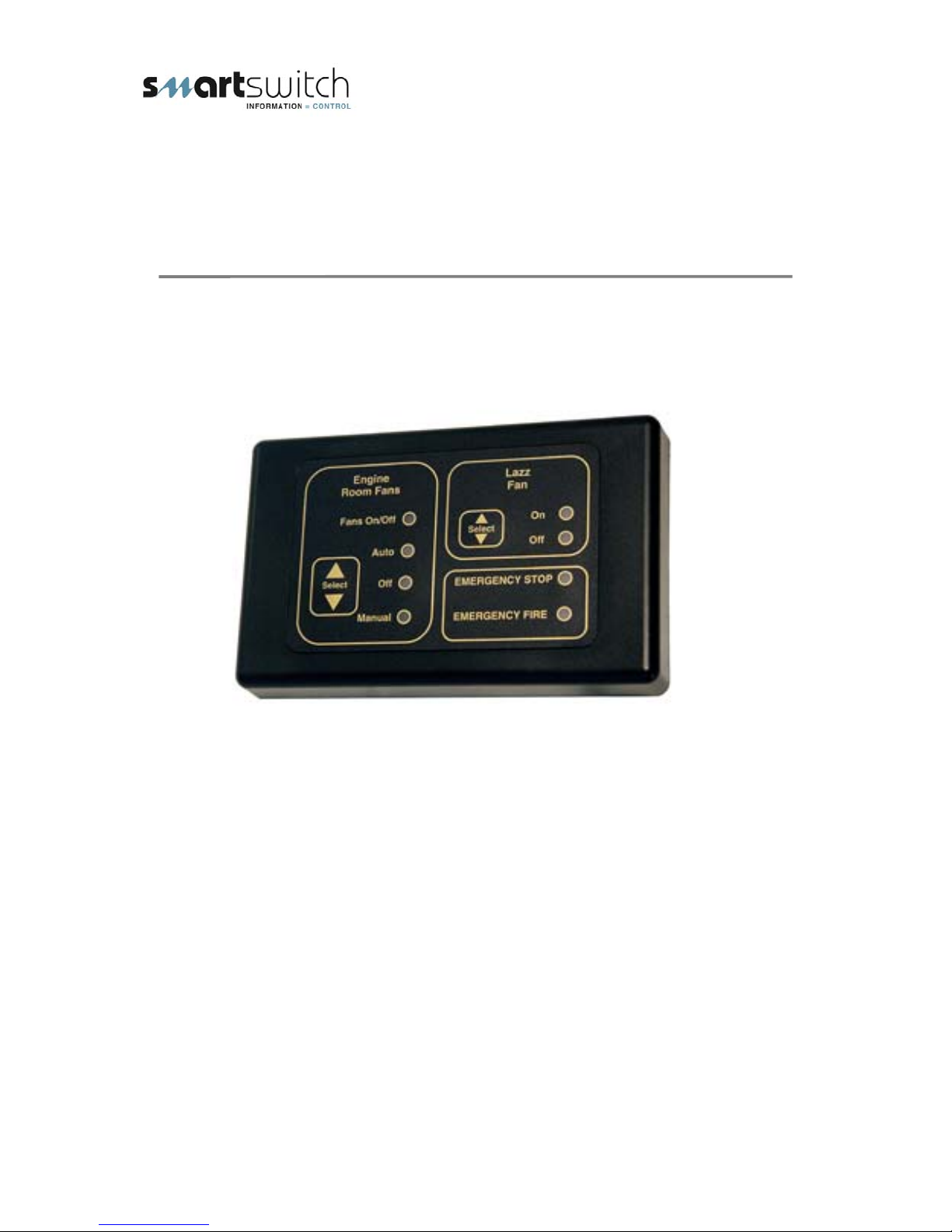
Engine Room Fan Controller
Installation Manual
FC-006
1
Page 2
pp
y
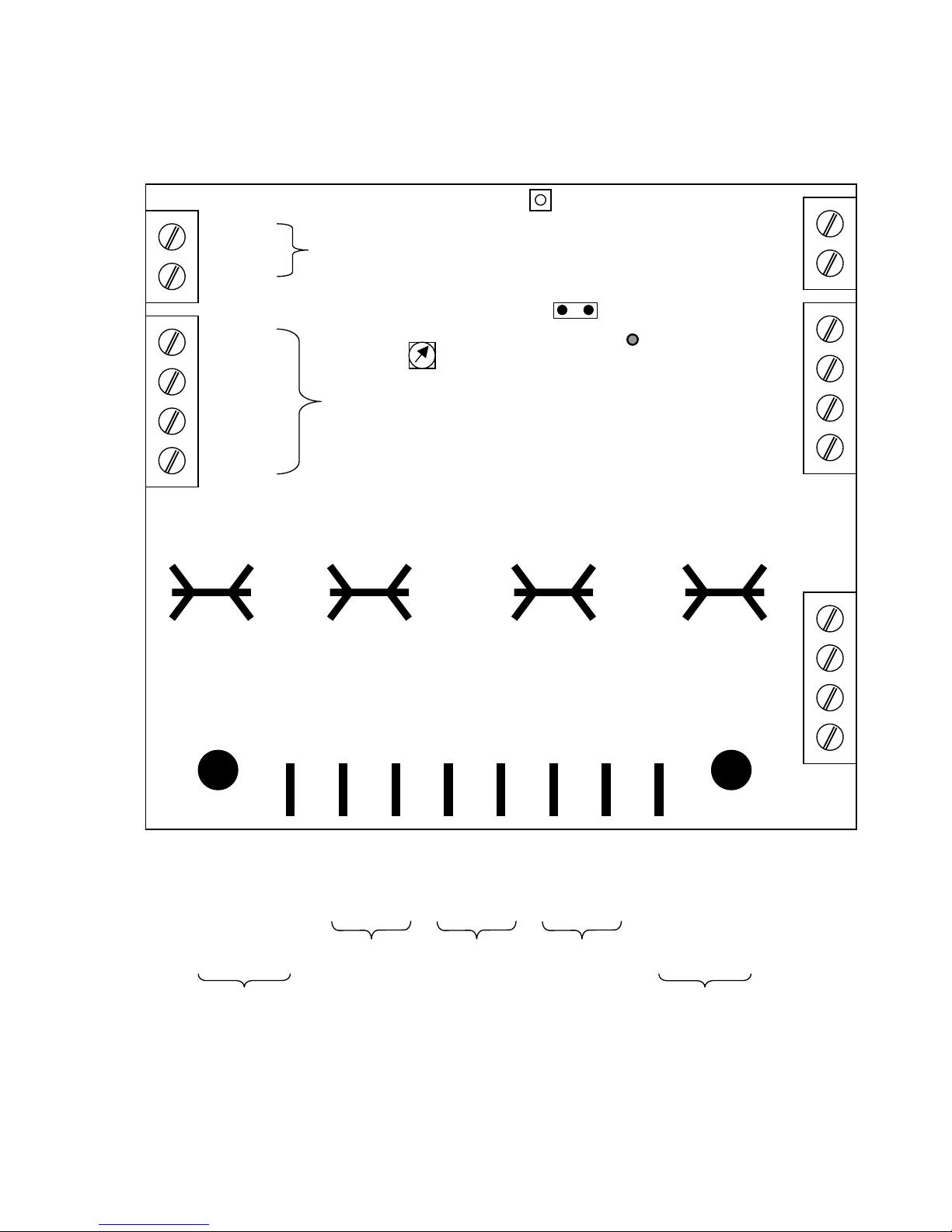
FC-006 Fan Controller Connections:
Figure 1
Batt +
Batt -
Logic power supply
Program Switch
Batt +
Batt -
Comms +
Comms -
To Keyboard
Emergency Fire
Rotary switch
Select Jumper
Rotary switch
LED
Program Switch
LED
Emergency Stop
Switch Input
Emergency Fire
Stop Input.
1
2
3
4
+ Fan Supply
Either connector
may be used
+ Fan Supply
+ Fan 1
Engine
- Fan 1
+ Fan 2
Engine Room
Reversable
- Fan 2
+ Fan 3
Lazz Fan
- Fan 3
Oil Pressure Switch
- Fan Su
- Fan Supply
l
Either connector
may be used
1
2
3
4
2
Page 3
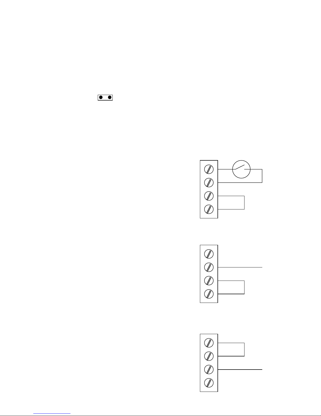
Emergency Fire Input Setup:
NOTE: Where indicated the Link wire MUST be installed
Jumper:
Emergency Fire
Select Jumper
This jumper sets the Emergency Input for either a normally open or normally closed input switch.
If the input switch is normally open install the jumper, if normally closed removed the jumper.
Input Setup:
Setup for clean relay contacts.
Setup for input switching to + VDC input.
Setup for input switching to GND.
Emergency Fire
Stop Input.
Emergency Fire
Stop Input.
Emergency Fire
Stop Input.
1
2
3
4
1
2
3
4
1
2
3
4
Switch
Link
Input
Link
Link
Input
3
Page 4

Oil Pressure Switch Input Setup:
NOTE: Where indicated the Link wire MUST be installed
Setup for clean contacts.
Note: The Link could also be a relay contact from
an engine running signal. In which case the oil
pressure input will only be looked at if the engine
is running.
Oil Pressure
Switch
Setup for input switching to + VDC input.
Note: The Input terminal could be
connected to the ignition switch instead of
using the oil pressure switch for engine
running signal.
Setup for input switching to GND.
Emergency Stop Input Switch:
The Emergency Stop input switch needs to be a normally
closed switch going open when activated.
Oil Pressure
Switch
Oil Pressure
Switch
Emergency Stop
Switch Input
Switch
1
2
3
4
1
2
3
4
1
2
3
4
Link
Input
Link
Link
Input
Switch
4
Page 5

Keyboard:
Lazzarette On / Off Switch:
Push to activate Fan 3, repeat to deactivate.
On Led = Green
Off Led = Red
Auto Switch:
Pushing this button allows to scroll between Auto / Off / Manual.
Fans On / Off LED:
This LED will be on (green) only when the engine room fans are actually ON and off
(red) when the fans are OFF.
Emergency Stop & Fire LED’S:
These LEDS will be on (red) if the Emergency Stop or the Emergency Fire inputs are
triggered. All Fans will be turned OFF
Keyboard Cable:
Maximum recommended length is 1000 meters.
5
Page 6

Operation For Normal Mode:
(Rotary switch in position 0)
Manual:
When switched to Manual Mode the engine room fans will turn On and stay On until
turn Off or placed in Auto Mode.
Off:
All fans Off
Auto:
When placed in Auto Mode and the engine starts the Fans will start after the
programmed “Fan Start Time” (see page 6) both Fans will run in the same direction.
If the Lazz fan is On it will be turned Off and placed in standby mode the Lazz On
LED will be flashing to indicate this, all Lazz times will be saved and suspended.
When the engine is stopped both Fan 1 and Fan 2 will be turned Off for the
programmed “Fan Stop Time” (see page 6) then both Fans will start again but Fan 2
will be reversed. The Fans will stay on until the programmed “Fan Run On Time” (see
page 6) at which time they will both turn Off.
If the Lazz was On and placed in standby, it will now resume its normal operation.
Emergency Stop:
If this input is triggered ALL Fans will be turned Off and the LED will turn On.
Emergency Stop:
If this input is triggered ALL Fans will be turned Off and the LED will turn On.
6
Page 7

Programming For Normal Mode:
(See Figure 1 for rotary switch and program switch details).
Programming the Fan Start Time: (Rotary switch to position D)
Explanation: After the engine is started the Fans will turn on, when the “Fan Start
Time” is reached.
e.g. fans will start 30 seconds after the engine is started
Turn the rotary switch to position D. Push the program switch (the LED will flash for
every key push). Each push will increase the time in increments of 1 second.
Max time = 10 minutes. System default = 30 seconds.
Switch the rotary switch back to position 0.
Programming the Fan Stop Time:
Explanation: After the engine has been stopped the Fans will stop for the ‘Fan Stop
Time” and then turn back on but with Fan 2 reversed.
Turn the rotary switch to position A. Push the program switch (the LED will flash for
every key push). Each push will increase the time in increments of 10 seconds.
Max time = 10 minutes. System default = 30 seconds.
Switch the rotary switch back to position 0.
Programming the Fan Run On Time: (Rotary switch to position 7)
Explanation: After the engine has been stopped and Fan 2 has been reversed, Fan
1 and Fan 2 will stay on for the ‘Fan Run On Time” and then stop.
Turn the rotary switch to position 7. Push the program switch (the LED will flash for
every key push). Each push will increase the time in increments of 1 minute.
Max time = 1.5 hours. System default = 30 minutes.
Switch the rotary switch back to position 0.
Ensure the Rotary Switch is turned back to position 0.
(Rotary switch to position A)
7
Page 8

Programming Normal Mode Continued
The Lazz Fan On and Off times can be programmed.
Lazz On Time:
(Rotary switch to position 4)
Turn the rotary switch to position 4. Push the program switch (the LED will flash for
every key push). Each push will increase the ON time in increments of 1 minute.
Max time = 1 hour. System default = 5 minutes.
Switch the rotary switch back to position 0.
Lazz Off Time: (Rotary switch to position 6)
Turn the rotary switch to position 6. Push the program switch (the LED will flash for
every key push). Each push will increase the OFF time in increments of 1 hour.
Max time = 20 hour. System default = 5 hours
Switch the rotary switch back to position 0.
The Lazz Fan ( if on ) after a motor shut down can be programmed to start
either, in the OFF or ON state. System default = On State.
Lazz Start On : (Rotary switch to position 8)
Turn the rotary switch to position 8. Push the program switch (the LED will flash).
Switch the rotary switch back to position 0.
Lazz Start Off : (Rotary switch to position 9)
Turn the rotary switch to position 9. Push the program switch (the LED will flash).
Switch the rotary switch back to position 0.
The Lazz Fan ( if on ) after a motor shut down can be programmed to stop for a
24 hour period. System default = OFF ( Not 24 hour ).
Lazz Off for 24 hour’s after a motor start :
(Rotary switch to position B)
Turn the rotary switch to position B. Push the program switch (the LED will flash).
Switch the rotary switch back to position 0. Repeat to change back.
If this mode is selected then after the motor has run the Lazz fan will be off for 24
hour’s then resume it’s normal running times.
Ensure the Rotary Switch is turned back to position 0
8
Page 9

Special Mode:
(Rotary switch in position F)
If the rotary switch is in position F the system will operate as follows.
Auto Mode:
When the engine is started both fan one and fan two will start, when the engine is
stopped fan two will turn off while fan will run on for the “Engine Run On Time” (which
is programmable) factory default time is 10 minutes.
When the “Engine Run On Time” is reached fan one will turn off.
Manual Mode:
Both fan one and fan two will turn on and stay on until either turned off or the unit is
placed in Auto mode.
Stand Alone Mode: (Rotary switch in position E)
Note: The Keyboard as shown on page 4 is NOT required in this mode.
If the rotary switch is in position E the system will operate as follows.
Inputs:
The oil pressure switch is engine run signal 1. (e.g. main engine)
The emergency fire stop switch input becomes the engine run signal 2. (e.g.
generator)
The emergency stop switch input is an Emergency Stop and all fans will be turned of
if activated.
Operation:
If either engine run signal is triggered, fan output 1, 2 and 3 will turn ON and stay on
until both engine run signals are off, then fan output 3 will turn OFF and fan output 1
and 2 will run on for the programmed Engine Run On Time and then turn OFF.
Stand Alone Mode 2:
(Rotary switch in position 5)
Note: The Keyboard as shown on page 4 is NOT required in this mode.
If the rotary switch is in position E the system will operate as follows.
Inputs:
The oil pressure switch is engine run signal 1. (e.g. main engine)
The emergency fire stop switch input becomes the engine run signal 2. (e.g.
generator)
The emergency stop switch input is an Emergency Stop and all fans will be turned of
if activated.
Operation:
If the engine run signal 1 is triggered, fan output 1, 2 and 3 will turn ON and stay on
until engine run signals 1 turns off, then fan output 3 will turn OFF and fan output 1
and 2 will run on for the programmed Engine Run On Time and then turn OFF.
If the engine run signal 2 is triggered, fan output 3 will turn ON and stay on until
engine run signal 2 turns off, then fan output 3 will run on for the programmed
9
Page 10

Lazz On Time and then turn OFF.
Programming the Engine Run On Time:
(Rotary switch to position C)
Turn the rotary switch to position C. Push the program switch (the LED will flash for
every key push). Each push will increase the ON time in increments of 1 minute.
Max time = 1 hour. System default = 10 minutes.
Switch the rotary switch back to position F.
Programming the Lazz On Time: (Rotary switch to position 4)
Turn the rotary switch to position 4. Push the program switch (the LED will flash for
every key push). Each push will increase the ON time in increments of 1 minute.
Max time = 1 hour. System default = 5 minutes.
Switch the rotary switch back to position 0.
All technologies, design and Intellectual property is owned by
Smart Switch Technologies L
Po Box 272, Waikanae. NZ
Phone 0064-4-293-4201 Fax 0064-4-293-4201
Email: info@smartswitch.co.nz
Web: www.smartswitch.co.nz
10
 Loading...