

Smart Start ns1074 Quick Installation Manual

4-BUTTON 1-WAY AUTOMATIC/MANUAL
TRANSMISSION REMOTE STARTER WITH
VIRTUAL TACH SYSTEM (AS PRG-1000
COMPATIBLE)
Notice
The manufacturer will accept no responsibility for any electrical damage resulting from improper installation of the product, be that either
damage to the vehicle itself or to the unit. This unit must be installed by a certified technician using all safet y devices supplied. Please
note that this guide has been written for properly trained Autostart technicians: a certain level of skills and knowledge is therefore
assumed. Please review the installation guide caref ully before beginning any work.
Warning
Before installing the unit, if installing on a vehicle with a manualt ransmission, test that the OEM Door Switch contacts of the vehicle work
well, and that the Parking Brake system operates properly. If installing on a vehicle with an automatic transmission, test that the vehicle
does not start when the gearshift lever is in the “Drive” position. If it starts in gear, reset the remote starter to manual transmission.
Doc#: 100810 Rev:1.0 © 2010 - 1W-AM-4B-A/M-HD - - FcN - Canada
QUICK INSTALLATION GUIDE
To obtain a copy of the installation guide, please visit our website at www.autostart.ca
TableofContents
Manual or Automatic Transmission setup 1
NEW FEATURE – Push To Start 2
NEW FEATURE – Hybrid Option 2
Entering Programming Mode 2
Programming the transmitter to the module 3
Entering Programming Options 3
Programming Options 3
Horn adjustment 4
Setting up the TACH 5
Virtual Tach adjustment 5
Multi-speed Tach Programming (if installed) 5
Transponder Programming 5
Resetting the Module 5
Bypass 5
NEW FEATURE – SmartStart 6
Testing 6
Diagnostics – Parking Light Flash Table 7
Diagnostic table for start failure. 7
Diagnostic table for shutdown. 7
The wiring diagram is at the middle of this guide.
MANUAL OR AUTOMATIC TRANSMISSION SETUP
This module may be installed on vehicles with manual or automatic transmissions. It is originally configured for
manual transmissions. If the vehicle you are working on is automatic, it is necessary to make a few quick and
easy modifications before the unit is connected. In the event that the configuration requires changes afterwards,
a complete reset will be necessary before those changes become effective.
To install this unit in a vehicle with a MANUAL transmission:
1. Make sure the Yellow loop on the PC board is connected. (Default)
2. Connect the Orange handbrake wire, located on the 12-pin harness, to the vehicle handbrake
switch. (-)
3. Connect the Blue/White (+) door input OR the Grey (-) door input wire, located on the 12-pin
harness, to the vehicle door pin wire. It will monitor all the doors of the vehicle (only use 1 of the 2
door trigger inputs).
4. Make sure the Purple TACH wire is installed on a TACH source – the TACH wire MUST be hooked
up when the module is set for a manual transmission.
5. Make all your regular connections.
6. Power up the unit by first inserting the 5-pin connector, then the 6-pin connector and finally the 12pin connector. The parking lights will flash 4 times.
7. When learning the transmitter, the parking lights will flash 5 times quickly.
8. Upon the first successful remote start, the system will lock the transmission settings to manual
mode.
To install this unit in a vehicle with an AUTOMATIC transmission:
1. Cut the loop on the back of the remote starter module (Yellow wire).
2. Make sure the Orange handbrake wire is not connected to any of the vehicle circuits (cut and
tape).
3. Make all the regular connections.
4. Power up the unit by first inserting the 5-pin connector, then the 6-pin connector and finally the 12pin connector. The parking lights will flash 4 times.
P. 2 http://www.autostart.ca Quick Installation Guide
5. When learning the first transmitter, the parking lights will flash 5 times quickly then give 2 slow
flashes.
6. Upon the first successful remote start, the system will lock the transmission settings to automatic
mode.
Note: If upon pressing the START/STOP button the parking lights give 3 slow flashes, make sure that the
Orange handbrake wire is not connected, the hand brake is not engaged and that the yellow loop is cut and
isolated/taped.
NEW FEATURE – PUSH TO START
Disabled by default, PTS mode is a special feature that is intended to facilitate the remote starter installation on
most Push To Start vehicles. With PTS mode enabled, the remote starter will offer the installer a negative start
output (to pulse the vehicle’s PTS switch), as well as a (+) brake switch output (no external relay necessary).
With PTS enabled, the White/Green wire on the 12 pin harness becomes your negative (-) PTS switch output. It
will give a one second output intended to pulse the PTS switch. Also, the Purple crank output becomes your
brake switch output (this will turn the brake circuit ON for crank).
NEW FEATURE – HYBRID OPTION
Warning: For automatic transmissions only.
This option is disabled by default. It can be enabled in Mode 3 of the programming options.
HYBRID mode is a special feature that is intended to facilitate the remote starter installation on most Hybrid
vehicles. With HYBRID mode enabled, the remote starter will give a four second crank output on its crank wire
(It will not rely on VTS to stop the crank cycle). The only way to shorten the four second crank output is to
program a tach signal to the remote starter. If a tach signal is programmed, the remote starter will act like
normal (the HYBRID feature should be used when a tach reference is not available from the vehicle or the
bypass being used at the time of installation).
ENTERING PROGRAMMING MODE
These are the programming buttons:
Complete step by step module programming
1) Entering Programming Mode
2) Programming the transmitter to the module
3) Entering Programming Options
4) Programming the options
5) Adjusting the Horn output (if installed)
6) Setting up the TACH, VTS or Multi-speed Tach
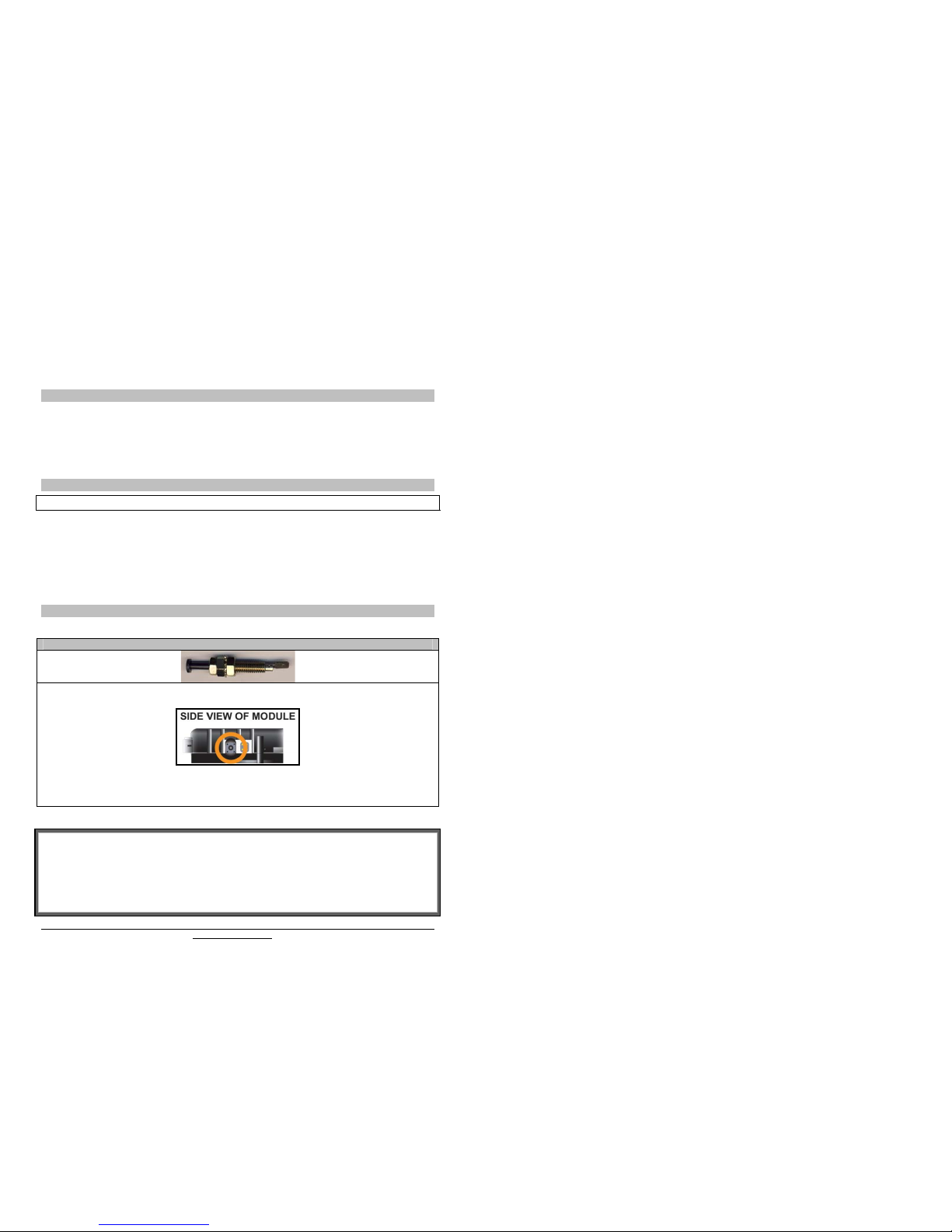
The Hood Pin
The Programming Assistance Button
(a.k.a. the P.A.B.)
The P.A.B. is located on the side of the module. This push button mimics the hood-pin switch in order to avoid
having to get out of the vehicle for programming. The P.A.B. will work only when the hood pin is installed
and the hood is up.
 Loading...