

SmartSight Networks MF24 Users Manual

USER’S MANUAL V1.2
(MF24-AV/ADV/AVr/ADVr)
Instructions on how to install, configure
and operate the MultiSite system
(North American Models)
Comlink Group Inc.
1800 Berlier St.
www.comlinkgroup.com
Laval, QC
H7L 4S4
Canada

ii
_____________________________________________________________________________________________
INFORMATION TO USER
This device complies with Part 15 of the FCC Rules. O peration is subjec t to the fo llowing
two conditions: (1) This device may not cause harmful inte rference, and (2) This device
must accept any interference received, including interference that may cause undesired
operation.
This equipment has been tested and found to comply with the limits for Class B Digital
Device, pursuant to Part 15 of the FCC Rules. These limits are designed to provide
reasonable protection against harmful interference in residential installation. This
equipment generates and can radiate radio frequency energy and, if not installed and used
in accordance with the instructions, may cause harmful interference to radio
communications. However, there is no guarantee that interference will not occur in a
particular installation. If this equipment does cause harmful interference to radio or
television reception, which can be determined by turning the equipment off and on, the
user is encouraged to try to correct the interference by one or more of the following
measures.
• Reorient or relocat e the receiving ant enna
• Increase the separation between the equipment and receiver
• Connect the equipment into an outlet on a circuit different from that to which the receiver
is connected
• Consult th e dealer or an experienced radio/TV technician for help
Any changes or modifications not expressly approved by the party responsible for
compliance could void the user’s authority to operate the equipment.

iii
_____________________________________________________________________________________________
WARRANTY
Each standard product manufactured by ComLink Group is warranted to meet all
published specifications and to be free from defects in material and workmanship for a
period of three (3) years from date of delivery as evidenced by ComLink G roup’s packing
slip or other transportation receipt. Products showing damage by misuse, abnormal
conditions of operation or Products which have been modified by Buyer or have been
repaired or altered outside ComLink Group’s factory without a specific authorization from
ComLink Group shall be excluded from this warranty. ComLink Group shall in no event be
responsible for incidental or consequential damages including without limitation, personal
injury or property damage.
ComLink Group’s responsibility under this warranty shall be to repair or replace, at its
option, defective work or parts returned to ComLink Group with transportation charges to
ComLink Group’s factory paid by Buyer and return paid by COMLINK. If COMLINK
determines that the Product is not defective within the te rms of the warranty, Buyer shall
pay all costs of handling and transportation. ComLink Group may, at its option, elect to
correct any warranty defects by sending its supervisory or technical representative, at
ComLink Group’s expense, to customer’s plant or location. ComLink Group shall in no
event be responsible for incidental or consequential damages including, without limitation,
personal injury or property damage.
SINCE COMLINK GROUP HAS NO CONTROL OVER CONDITIONS OF USE, NO
WARRANTY IS MADE OR IMPLIED AS TO SUITABILITY FOR CUSTOMER’S
INTENDED USE. THERE ARE NO WARRANTIES, EXPRESSED OR IMPLIED,
EXCEPT AS STATED HEREIN. This limitation on warranties shall not be modified by
verbal representations.
Equipment shipped EX-Works ComLink Group factory shall become the property of Buyer,
upon transfer to the common carrier. Buyer shall com municate directly wi th the carr ier by
immediately requesting carrier’s inspection upon evidence of damage in shipment.
Buyer must obtain a Return Materials Authorization (RMA) number and shipping
instructions from ComLink Group prior to returning any Product under warranty. DO NOT
RETURN ANY COMLINK GROUP PRODUCT TO THE FACTORY UNTIL RMA AND
SHIPPING INSTRUCTIONS ARE RECEIVED.
Microflex AV/ADV/AVr/ADVr North-American user’s manual / Rev 1.2

iv
_____________________________________________________________________________________________
Customer Support
If after reading this manual, you encounter any trouble installing or using any MultiSite
product, please contact your local distributor. If problems are not solved, you can call
ComLink Group’s Customer Service for assistance during normal business hours (EST).
The fax and phone numbers are:
Ph: (450) 686-9000 (888) 494-7337 (North America)
Fax: (450) 686-0198
You may also e-mail your inquiries and comments at the following address:
techsupport@comlinkgroup.com
About this User Manual
This User’s Manual covers the information and procedur es on installing, configuring and
using the Microflex MF24-AV/Avr/ADV/ADVr modules. This manual is also a reference for
persons who must perform or coordinate the tasks associated with programming and
managing a Multisite wireless network.
To control the video display and Pan-Tilt-Zoom functions in multipoint, you will need to
read Chapter 5 to learn how to use the Pelco KBD4000
point-to-point video link and do not want to take advantage of the 4 camera inputs and
Quad View display of these 4 cameras, you do not require the KBD4000 and t herefore do
not need to read this section. You will need, however, to read Chapter 4 to learn how to
program the DATA1 serial port of both video transmitter and receiver for the specific data
rate of the Pan-Tilt-Zoom system you wish to use.
For customers using a RS-485/422 port, you may need to change the port to RS-232
setting if you configuration of the module is required. Please review Appendix E for
converting from RS-485/422 to RS-232 and vice-versa (Appendix G for FV module)
For customers who have ordered a Line Level audio interface and plan to use a leased or
dry line, please refer to Appendix G for interface assistance.
Prerequisite Knowledge
Throughout the user's manual there are explanations and procedures that presume
working familiarity with radios, as well as basic digital data communication concept s and
practices, and an understanding of the concepts underlying telecommunication systems.
If you are not familiar with the concepts and practices involved in these disciplines, we
recommend that you familiarize yourself with them before proceeding.
TM
keyboard. If you are using a
v
_____________________________________________________________________________________________
Manual Conventions
Suggestion
Note
Warning
Microflex AV/ADV/AVr/ADVr North-American user’s manual / Rev 1.2

vi
_____________________________________________________________________________________________
Table of Content
CHAPTER 1 OVERVIEW......................................................................................................1
1.1 P
1.2 F
1.3 A
1.4 E
1.5 I
1.6 S
CHAPTER 2 MICROFLEX INSTALLATION AND OPERATION .................................9
2.1 M
CHAPTER 3 PROPER MICROWAVE NETWORK PLANNING..................................13
3.1 RF P
3.1.1 Network Planning..................................................................................................13
3.1.2 Evaluating System Gain Requirements.................................................................16
3.1.3 Verifying Line of Sight and Fresnel Zone Clearance............................................19
3.1.4 On-Site Testing......................................................................................................20
3.2 C
RODUCT
EATURES
PPLICATIONS
XTERNAL MODULE DESCRIPTION
NTERNAL DESCRIPTION
ETTING THE MASTER OR SLAVE MODE
ICROFLEX SETUP GUIDE
OPING WITH INTERFERENCE
..........................................................................................................................1
........................................................................................................................1
..................................................................................................................2
....................................................................................2
...................................................................................................4
................................................................................................9
LANNING
................................................................................................................13
.........................................................................................22
..........................................................................8
CHAPTER 4 MNM CONFIGURATION SOFTWARE INTEGRATION....................... 24
4.1 I
4.2 U
NSTALLING THE
SING MULTISITE NETWORK MANAGER
MNM..................................................................................................24
(MNM)..........................................................25
4.2.1 Launching the MNM Programmer........................................................................25
4.3 M
AIN OPERATIONS
.........................................................................................................27
4.3.1 Network List ..........................................................................................................28
4.3.2 Unit Properties......................................................................................................28
4.3.3 Menu Bar............................................................................................................... 28
4.3.4 Tool Bar.................................................................................................................29
4.4 U
NIT PROPERTIES
...........................................................................................................29
4.4.1 General.................................................................................................................. 29
4.4.2 Audio .....................................................................................................................30
4.4.3 Data.......................................................................................................................32
4.4.4 Radio .....................................................................................................................33
4.4.5 Video...................................................................................................................... 34
4.5 D
4.6 F
4.7 M
IAGNOSTICS
IRMWARE UPDATE
ISCELLANEOUS
.................................................................................................................34
............................................................................................................36
.......................................................................................................35
4.7.1 Factory Reset (same as hardware switch SW1; see chapter 1) ............................ 36
4.7.2 Unit Reset (same as hardware switch SW2; see chapter 1).................................. 36
CHAPTER 5 USING THE KBD4000 IN A MULTISITE NETWORK............................37
5.1 C
5.2 C
5.3 C
5.4 C
5.5 U
ONFIGURING THE
ONFIGURING THE MICROFLEX VIDEO RECEIVER
ONNECTING THE
ONNECTING THE
SING THE
KBD4000
KBD4000TM....................................................................................38
KBD4000
KBD4000
TM
TM
TO THE MICROFLEX VIDEO RECEIVER
TM
TO MULTIPLE MICROFLEX RECEIVERS
IN A MICROFLEX VIDEO NETWORK
..........................................................38
..........................39
..........................39
.........................................41

vii
_____________________________________________________________________________________________
5.5.1 Microflex ID’s.......................................................................................................41
5.5.2 Camera selection in Full Screen Display..............................................................41
5.5.3 Multiple Camera display.......................................................................................42
5.5.4 Menus ....................................................................................................................42
5.6 P
5.7 P
5.8 U
5.9 KBD4000
AN, TILT AND ZOOM FUNCTIONALITY
ASSWORD
SING ONE
.....................................................................................................................45
KBD4000
TM
KEYBOARD DEFINITIONS
TM
AND MULTIPLE VIDEO RECEIVERS
...........................................................................44
. ..........................................45
...........................................................................46
F
IGURE
F
IGURE
IGURE
F
F
IGURE
IGURE
F
IGURE
F
F
IGURE
F
IGURE
F
IGURE
IGURE
F
F
IGURE
F
IGURE
IGURE
F
F
IGURE
IGURE
F
F
IGURE
IGURE
F
F
IGURE
IGURE
F
F
IGURE
IGURE
F
1- M
ICROFLEX AVR
2- M
ICROFLEX
3 - M
ICROFLEX
4 - M
ASTER AND SLAVE MODE SELECTION
5 – M
ICROFLEX
6 - B
ASIC MULTIPOINT CELL
7 - M
ULTIPOINT NETWORK WITH REPEATER
8 - M
ULTIPOINT NETWORK WITH TWO REPEATERS
9 - D
IFFERENCE BETWEEN FRESNEL ZONE AND VISUAL LINE OF SIGHT
10 – R
11 – W
12 – S
UN DIALOG BOX
ELCOME SETUP DIALOG BOX
ETUP COMPLETE DIALOG BOX
13 – MNM M
14 – C
OMMUNICATION CONFIGURATION DIALOG BOX
15 – MNM M
16 – MNM T
17 – D
18 – D
19 - S
20 - S
21 - E
IAGNOSTIC WINDOW
IAGNOSTIC WINDOW
TRETCH TO ELONGATE SEALANT TAPE WHILE WRAPPING OVER CONNECTION
TRETCH TO ELONGATE ELECTRICAL TAPE WHILE WRAPPING OVER SEALANT TAPE
LECTRICAL TAPE WRAPPED TIGHTLY AGAINST CABLE JACKET, TYPICAL BOTH ENDS
OOL BAR
/ADVR – E
AV/ADV – E
– I
NTERNAL DESCRIPTION
ADV/ADV
XTERNAL VIEW
XTERNAL VIEW
R CABLING
.............................................................................................14
.....................................................................................................24
AIN VIEW
AIN VIEW SECTIONS
.....................................................................................................26
......................................................................................................29
................................................................................................35
................................................................................................36
..................................................................2
......................................................................3
...........................................................................4
..........................................................................8
.............................................................................11
.....................................................................14
...........................................................15
...........................19
.................................................................................24
................................................................................25
.....................................................26
.....................................................................................27
...........51
...51
52
T
ABLE
T
ABLE
ABLE
T
T
ABLE
1 – A
NTENNA GAIN
2 – W
EATHER DEPENDENT RATINGS
3 – D
ISTANCE VS PATH LOSS
4 – 0.6F1 V
ALUES AT VARIOUS DISTANCES
............................................................................................................16
...................................................................................17
.............................................................................................18
.......................................................................20
Microflex AV/ADV/AVr/ADVr North-American user’s manual / Rev 1.2

1
_____________________________________________________________________________________________
CHAPTER 1 Overview
1.1 Product
The Microflex is your solution for reliable and cost-effective point-to-point or
multipoint wireless video communications. This module supports video and data
and/or telephony applications.
Capabilities of the Microflex are:
• All digital multipoint networking using Demand Assigned
TDMA/TDD access
• Supports up to 16 remote video, voice and data terminals
• Protocol transparent point-to-multipoint polled data port
• Support of multiple point-to-point data ports (up to 1 6)
• User-friendly PC/Windows
Multisite Network Management (MNM)
TM
based system programming and
1.2 Features
Microflex provides the following features:
• Up to four (4) video cameras per transceiver modules
• One or two integrated analog telephone line interface (subscriber
or telco interface) and/or line level audio
• One or two asynchronous data ports (RS-232 or RS-485 levels)
• Reliable polled data communications using error detection and
correction algorithms
• Capability to operate in PBX or DOD (direct outward dial) voice
mode
Microflex AV/ADV/AVr/ADVr North-American user’s manual / Rev 1.2
2
_____________________________________________________________________________________________
1.3 Applications
The Microflex is capable of operating in a point-to-point as well as a point-tomultipoint environment.
In a typical point-to-multipoint configuration, one Microflex must be set in master
mode to act as a network controller (typically installed at the base). It communicates
with several remote Microflex (up to 16) set in slave mode, on a single microwave
frequency. If a single remote Microflex is used, the system becomes a point-to-point
link.
___________________________________________________________________
Chapter 4 provides a comprehensive description of the MNM configuration software. The
Microflex is typically shipped with its factory default configuration unless indicated
otherwise on the configuration s heet attached. The MNM software may have to be us ed
to configure each Microflex for the required application.
___________________________________________________________________
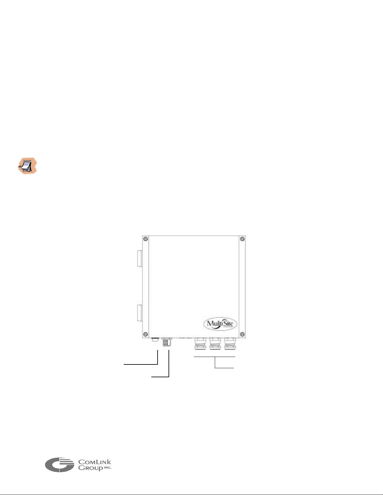
1.4 External module description
Status indicator
RF connector
(N type female)
Figure 1- Microflex AVr/ADVr – External view
Aluminum cable gland
connectors (for video,
power/audio/data cable entry)
3
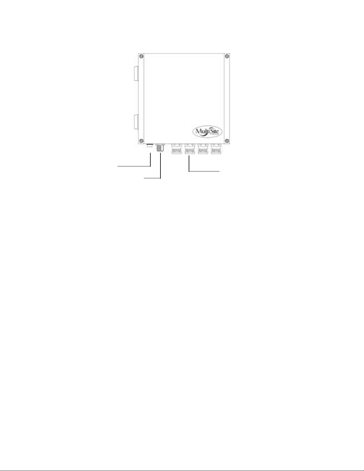
_____________________________________________________________________________________________
Status indicator
RF connector
(N type female)
Aluminum cable gland
connectors (for video,
power/audio/data cable entry)
Figur e 2- Microflex AV/ADV – Ext ernal vi ew
The Microflex electronics is enclosed in a weather-tight cast alum inum module. All
cable entries and the indicator are mounted on the underside of the module to
maintain its weather-tight properties. The underside of the Microflex integrates one
(1) visual indicator with the following function:
• STATUS - Bi-color indicator (Green or Red)
This indicator illuminates Green when the module is operating normally and has
not detected an internal fault. It will turn Red at power up if the module detects
an internal fault. It will flash Green during radio firmware update (see chapter 4;
configuring the network with the MNM software). Steady off at power up also
indicates an internal failure.
Microflex AV/ADV/AVr/ADVr North-American user’s manual / Rev 1.2
4
(D2)
b
(
(
(
_____________________________________________________________________________________________
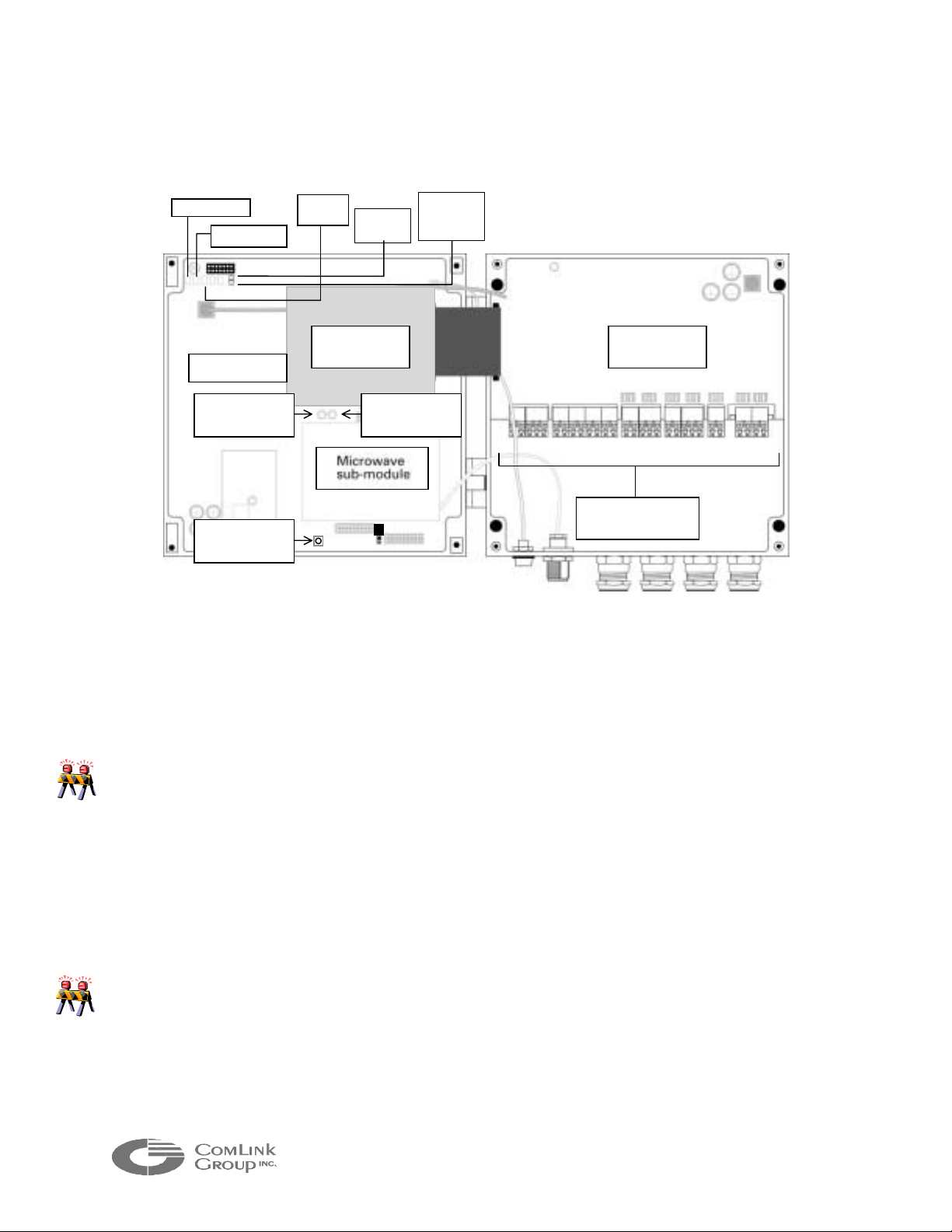
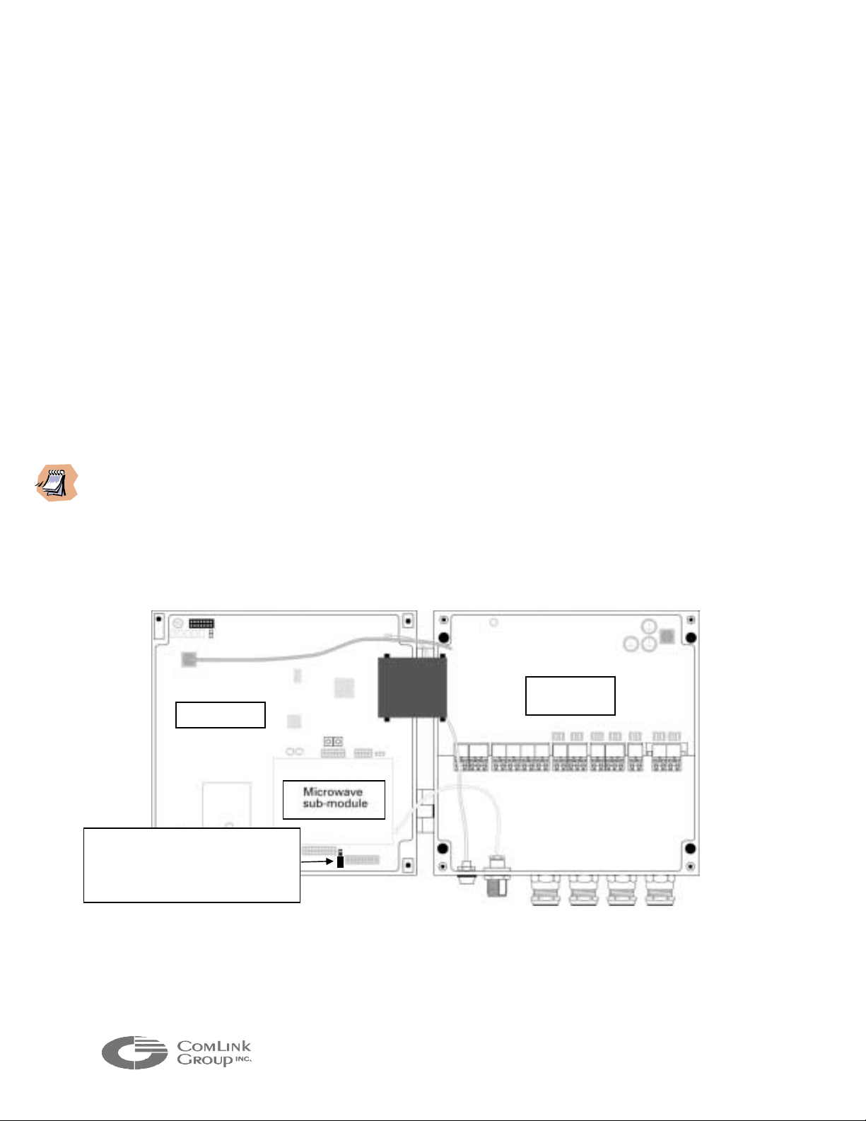
1.5 Internal Description
Status (DS1)
Power (DS2)
Comms
(DS3)
Phone
line (D1)
Carrier
Detect-
CD
Protection
Board
Interconnection
locks
Main Board
Reset Switch 2
SW2)
Reset Switch 3
SW3)
Video Codec
Board
Reset Switch 1
SW1)
Figure 3 - Microflex – Internal description
All connections to the Microflex including power, video, data and audio cabling are
made via pluggable industrial terminals. The signal description for each terminal is
indicated on a cabling label inside the enclosure.
____________________________________________________________________________
Care must be taken not to mix a Microflex FXS interface and FXO interface when
connecting the audio signals. Connecting a telephone line (FXO) instead of telephone
set can damage the FXS sub-module. A label at the back of the enclosure indicates the
audio option selected (O for FXO, S for FXS and L for line level).
____________________________________________________________________________
The industrial terminals are mounted on an interconnect ion board. This removable
board integrates a two stage surge/lightning protection circuit providing industrial
type protection for the main electronics.
____________________________________________________________________________
Each surge or lightning strike weakens the protection circuitry. It is recommended in
lightning prone geographical areas and as part of a maintenance program, to replace the
protection board every 2 years. Please contact ComLink factory for part number and
ordering procedure.
____________________________________________________________________________
The interconnection board connects to the main Microflex board via a pluggable
ribbon type cable assembly. If this ribbon needs to be disconnected for

5
_____________________________________________________________________________________________
maintenance, do not pull the ribbon as this may damage the cable assembly. Grab
the connector on the main PCB side and pull carefully.
The main board integrates five (5) visual indicators for troubleshooting as well as an
RF signal strength (RSSI) bargraph indicator to align the antenna and determine the
signal margin available:
• STATUS (DS1) - Bi-color indicator (Green or Red)
This indicator is equivalent to the external STATUS LED indica tor. It illuminates
Green when the module has not detected an internal fault and is operating
normally. It will turn Red at power up if the module detects an internal fault. It
will flash Green during radio firmware update (see chapter 4; configuring the
network with the MNM software).
• POWER (DS2) - Bi-color indicator (Green or Red)
This indicator illuminates Green when there is at least +10VDC supplied to the
interconnect board and the power supply used has an appropriate capacity
(typically 1A @ 15 VDC). It will illuminate Red if power is below +10 VDC, if
capacity is insufficient or if there is an internal problem creating excessive power
consumption.
• COMMS (DS3) - Bi-color indicator (Green or Red)
This indicator flashes Red during power-up if the radio module is not properly
detected. Following power-up the LED behavior will depend on the module
configuration:
(a) Master Mode Configuration:
It will flash Green at a rate of 2 flashes per second following powering-up
sequence. It will remain in this state if it is able to communicate with a r emote
Microflex set in Slave Mode. If it cannot communicate with a slave Microflex, it
will flash Red at a rate of 2 flashes per second. It will flash G reen at a rate of 8
flashes per second when there is voice or data activity between the module and
another Microflex or when the remote slave Microflex identif ies itself (once every
30 seconds).
(b) Slave Mode Configuration:
If it is not capable of communicating with a master Microflex It will remain off
following powering-up sequence. It will fl ash Green at a rate of 2 flashes per
second if it is able to communicate with a master Microflex. It will flash Green at
a rate of 8 flashes per second when there is voice or data activity between the
module and a master Microflex or every time it transmits its ID to the master
Microflex (once every 30 seconds on average but at random times).
_
Microflex AV/ADV/AVr/ADVr North-American user’s manual / Rev 1.2

6
_____________________________________________________________________________________________
__________________ ________________________________________________________
If the three (3) LEDs, power, Status and Comms are steady green simultaneously, the
Microflex is in its ‘’loader mode’’. Proper firmware has to be downloaded in the Microflex
for the module to be operational. Such download cannot be done over the RF network, it
must be performed locally (see chapter 4 for further details)
___________________________________________________________________
• PHONE/LINE (D1) – Green indicator
This indicator flashes 8 times per second in synch with the ring signal. The
indicator illuminates steady when a telephone call is in progress.
• CD (D2) - Green indicator
This is the RF carrier detect indicator. The LED behavior will depend on the
module configuration:
(a) Master Mode Configuration:
It will flash Green with varying intensity when activity is occurring in the network
(data or voice communications). The more the network is loaded, the more
intense the LED will glow. If there is no activity and the remote Microflex
modules can identify themselves to the master module, the LED will be on
momentarily every time it receives an ID packet (once every 30 seconds).
(b) Slave Mode Configuration:
It will flash green at a rate of at least 20 times per second (almost steady green)
when receiving a valid signal from the master module.
____________________________________________________________________________
The CD LED will not flash green if submitted to interference from nearby transmitters
operating in the same RF band. Such interference may however cause the LED to flash
intermittently by corrupting valid data packets received from another Microflex. The LED
may also flash intermittently if the signal received is at the limit of the receiver
sensitivity. The RSSI level can be used to differentiate between the two (2) conditions.
___________________________________________________________________
• RSSI (DS7 to DS16) - Green indicators
A ten (10) LED indicator bar graph is used to provide received signal strength
(RSSI). The RSSI indicators illuminate Green. RSSI values are not factory
calibrated and can have an error of +/- 4 dB as compared to true RSSI.

7
_____________________________________________________________________________________________
Microflex RSSI
INDICATOR LED RSSI (dBm)
Indicator DS16 (min) -101 +/- 4 dB
Indicator DS15 -98 +/- 4 dB
Indicator DS14 -95 +/- 4 dB
Indicator DS13 -92 +/- 4 dB
Indicator DS12 -89 +/- 4 dB
Indicator DS11 -83 +/- 4 dB
Indicator DS10 -77 +/- 4 dB
Indicator DS9 -71 +/- 4 dB
Indicator DS8 -65 +/- 4 dB
Indicator DS7 (max) -59 +/- 4 dB
The minimum signal level at which the Microf lex can operate depends on the data
rate setting. At high bit rate (558 kbps), the Microflex offers a -96 dBm receiver
sensitivity (@10-5 BER). By decreasing to medium bit rate (384 kbps), the
sensitivity increases to –98 dBm and at low bit rate (192 kbps), to -101 dBm.
____________________________________________________________________________
The bit rate should always be set to the mini mum required to obtain the most robu stness
to interference and the best receive sensitivity. The bit rate required depends on the
system load and the nature of the data transmitted. For most video applications the
medium data rate setting is a good compr omise between link robustness and v ideo quality.
For mixed data, audio, and video applications, the radio data rate used will depend on the
number of remote stations used. It is recommended to use mediu m rate for mixed sig nals
applications.
____________________________________________________________________________
The Microflex main electronics board integrates 3 switches offering the following
functions:
• RESET SWITCH 1 (SW1) – Reset to factory default
A reset-to-factory-default switch (SW1) can be triggered if the Microflex fails to
respond. This may be useful following the download of a corrupted or invalid
program or improperly programming the module using the MNM software (see
chapter 4). The switch must be held for at least 5 seconds while the power is ON
for a reset to be valid. Following a reset, the Microflex will need to be
programmed for proper operation in the network (see Appendix A for default
factory values) .
Microflex AV/ADV/AVr/ADVr North-American user’s manual / Rev 1.2
8
j
p
_____________________________________________________________________________________________
• RESET SWITCH 2 (SW2) – Hardware reset
A hardware reset can be made by momentarily pressing the SW2 switch. This
can be useful if the module appears not to be responding properly.
• RESET SWITCH 3 (SW3) – radio loader software
RESERVED
1.6 Setting the Master or Slave Mode
The Microflex main electronic board integrates a two (2) posit ion jumper to set the
module for Master or Slave mode operation. Refer to the illustration below for
proper position in both modes.
____________________________________________________________________________
A Multisite network must have a single Master module. If one Microflex is set in Master
mode, all other modules should be set in Slave mode. The Master module should ideally be
installed in an accessible location, typically at the base station. The only exception to this
is for a point-to-point video link. In point-to-point, it is best to set the MF24-ADV in
Master Mode and the MF24-ADVr is Slave Mode. This allows a higher video data
throughput (300 kbps sustained) and slightly higher quality.
___________________________________________________________________
Protection
Main Board
Jumper setting (master mode); Set
umper on two (2) upper pins for
slave mode and two (2) lower
ins for master mode
Board
Figure 4 - Master and Slave mode selection

9
_____________________________________________________________________________________________
CHAPTER 2 Microflex installation and operation
Your Microflex shipment should contain the following items:
• Microflex module with requested options
• Pole mounting bracket with two (2) stainless steel collars (for
0.75-2 inch poles unless an optional mount has been ordered)
• 15 VDC external power supply (Optional)
• Antenna (Optional)
• Microflex configuration sheet
• User’s manual (one set per system ordered)
• MNM based configuration diskettes (one set per system ordered)
___________________________________________________________________
Check the material against the packing lis t to make sure y ou have received ever ything. If
something is missing or if you discover shipping damage, please contact your distributor.
___________________________________________________________________
2.1 Microflex Setup Guide
Use the guidelines in the following subsection to assist you in cabling and installing
the Microflex.
STEP 1 Installing the Microflex module
The Microflex is shipped with a mounting bracket. This bracket is supplied with a
special water-sealing gel backing. This backing must not be removed in order to
maintain the enclosure weather-tight feature. Three (3) stainless steel screws are
also supplied to install the bracket on the back of the Microflex enclosu re. Mount
the bracket to the back of the enclosure and align the screws with the mounting
holes. Tighten the three (3) screws firmly while being careful not to strip the
aluminum threads. Some gel may flow out from under the bracket while tighte ning.
This extra gel can be removed with water and mild soap or an alcoholic solution.
Using the mounting bracket and collars supplied, the Microflex can be mounted on
any pole with a 18-50 mm (0.75-2.0 inch) diameter. ComLink also supplies
mounting brackets for mounting on walls and larger collar size f or mounting on light
poles or other large diameter poles. Contact ComLink factory if you require a
different mounting option than the one supplied.
Microflex AV/ADV/AVr/ADVr North-American user’s manual / Rev 1.2

10
_____________________________________________________________________________________________
STEP 2 Installing the antenna
The Microflex is designed for outdoor installation, next to the antenna. Such
installation minimizes cable losses thereby maximizing link margin. Install the
Microflex module with its antenna on an appropriate mast or t ower. Depending on
whether the antenna has a pigtail or not, you may need to install a coaxial cable
jumper (with N connectors) between the Microflex and antenna. The coaxial cable
recommended is an RG-142 double shield (or equivalent) with a maximum leng th of
3 meters to reduce cable loss (use quality type N clamp connectors to ensure a
watertight setup).
____________________________________________________________________________
Install the Microflex module at the same elevation as the antenna for best lightning
protection. If the Microflex module is installed several meters lower than the antenna, a
2.4 GHz lightning arrester should be used.
Never exceed antenna gains of 11 dBi. The only exception is when
you have significant cable losses. For each dB of cable loss, you can
add 1dB of antenna gain
___________________________________________________________________
___________________________________________________________________
.
Always install the antenna away from wires, pow er lines and trees for optimu m safety and
performance. For more information on antenna installation, refer to the manufacturer’s
documentation included with the antenna.
___________________________________________________________________
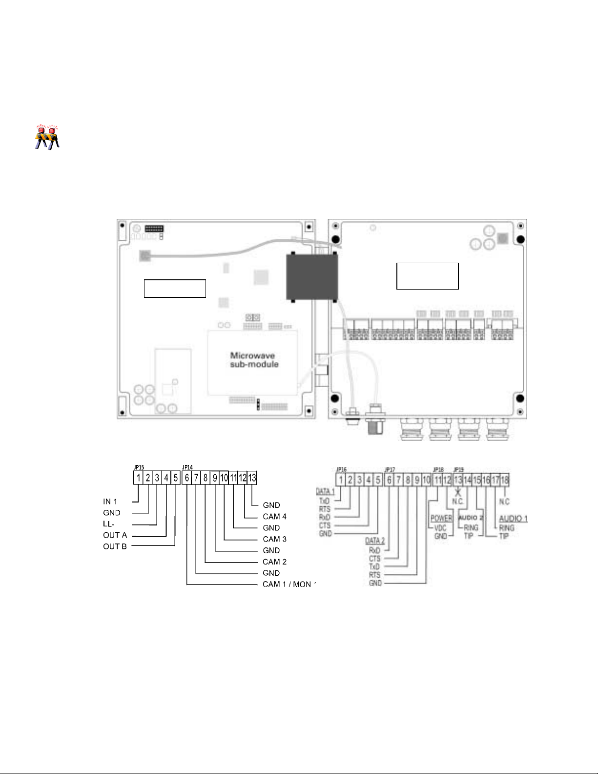
STEP 3 Connecting powe r, audio and data
Connect the power (12-15 VDC recommended), video, audio and data ports
according to the label at the bottom of the Microflex enclosure (see illustration on
next page). The video signal should be carried on RG-59 coaxial cable.
The power and audio signals can be carried using the same cable. This cable
should contain 4 to 5 pairs with an overall shield
mm diameter) or larger for optimum performance. Use 2 pairs for the audio and 2-3
pairs to carry power (this will reduce voltage drop between the power supply and the
Microflex).
The data should be carried using a low capacitance non twisted pair
communications cable with an overall shield
capacitance conductor will support long cable runs (50-80 meters) for RS-232
signals. The two (2) data ports can use a single multi-conductors cable.
and have an AWG of 20 (0.81
. A 24 gauge (0.51 mm diameter) low
11
_____________________________________________________________________________________________
____________________________________________________________________________
If you are planning to install a long cable extension between the Microflex and the
cameras, PLC/computer equipment and/or the phone equipment, it is highly
recommended to protect these equipments from lightning and power transients (the
Microflex is well protected and does not require additional protection). Several
manufacturers provide protection equipment for video, phone and data ports. ComLink
can provide a list of recommended equipment on request.
____________________________________________________________________________
Protection
Main Board
JP 14JP 15
Board
JP 16 JP 17
JP18
JP 19
Figure 5 – Microflex ADV/ADVr cabling
STEP 4 Connecting the Microflex for programming
The Microflex Data1 port (JP16) is used for both data applications and module
Microflex AV/ADV/AVr/ADVr North-American user’s manual / Rev 1.2

12
_____________________________________________________________________________________________
programming. Both Data1 port and Data2 port are configured as DCE interfaces.
They must be connected to a DTE interface for proper operation.
Connect the RS-232 TX, RX and GND signals (RTS/CTS not required) to the
available COM port of your PC running the MNM sof tware. The MNM software will
automatically convert the Microflex Data port 1 to terminal mode (configuration
mode) when started. The Microflex converts its Data port 1 back to its data
application mode following 30 seconds of inactivity from MNM on Data port 1.
___________________________________________________________________
In point-multipoint applcations, DATA 1 is used to transfer PTZ commands. If you have
ordered an RS-485 interface, DATA 1 is configured for RS-485 signal levels. You will not
be able to communicate with the module using a computer and MNM software in such case.
A RS-485 to RS-232 signal converter plug must be used to communicate between the
Microflex and the computer. Such item is not expensive and available from most
telecommunication equipment distributor .
___________________________________________________________________
STEP 5 Verifying the indicators for proper operation
Upon power up, the indicator STATUS indicator on the outside of the enclosure
should turn STEADY GREEN. Review Chapter 1 to understand how the indicators
on the Microflex main board should behave under normal conditions.
____________________________________________________________________________
If the POWER or STATUS indicator turns red momentarily (2 seconds or more) or stays
off at power up, there is a problem with the Microflex or the power supply. Please
contact ComLink technical support team for assistance.
____________________________________________________________________________
STEP 6 Completing the Installation
You have now completed the Microflex initial installation. Once the Microflex is
properly installed it will need to be configured. Please review Chapter 5 ‘’Using the
MNM Software’’ to complete this final step.
 Loading...