

S1500e Series
User Manual


S1500eTM Series
Firmware Release 2.60/3.0
User Manual

Copyright SmartSight Inc., 2003
All rights reserved. No part of this publication may be reproduced,
stored in a retrieval system or transmitted, in any form or by any
means, electronic, mechanical or otherwise, without the prior written
permission of SmartSight.
S1500eTM Series User Manual
Firmware Release 2.60/3.0
Published by:
SmartSight Networks Inc.
1800 Berlier Street
Laval (Quebec)
Canada
H7L 4S4
www.smartsightnetworks.com
Publication date: December 22, 2003
The SmartSight logo, SmartSight, S1500e, S1502e, S1504e,
S1508e, nDVR, and Versalis are trademarks of SmartSight Networks
Inc. Any other product names mentioned herein are the trademarks
or registered trademarks of their respective owners.
While every reasonable effort has been made to ensure the accur acy
of this document, SmartSight makes no warranty of any kind and
assumes no responsibility for errors and omissions. No liability is
assumed for incidental or consequential damages in connection with
or arising from the use of the information contained herein.

Table of Contents
Preface........................................................................v
Who Should Read this Manual ............. .............. ...... vi
How to Use this Manual ......................................... vi
Contents ........................................... ............. vi
Conventions .................................................. vii
Related Documentation .................................. viii
Related SmartSight Products ......... .............. .... viii
About Us . .............. ............... .................. ............. ix
Warranty .............................................................x
Chapter 1 Overview................................................ 1
About the S1500e Series .......................... ........... ...2
Physical Characteristics ....................... ..............2
Security ......................................... .................2
Video .............................................................3
Shipment .............................................................4
Unit Casing Description ................. .................. .......5
S1500e and S1502e .........................................5
S1508e ..........................................................6
S1504e ..........................................................7
Chapter 2 Network Planning.................................. 9
Chapter 3
Configuring the Unit .......................... .............. ..... 12
Configuring and Installing the Unit..... 11
Computer Requirements .................................. 12
Setting Unit Parameters ............................. ..... 12
iii

Table of Contents S1500e Series
Performing a Point-to-Point Connection ..............15
Installing the Unit ............. ........... ........... ............. 17
Performing Serial Connections .............. .............. ...18
Configuring the I/Os ....................... .................. ...20
Alarms .........................................................21
Audio ...........................................................21
Performing a Hardware Reset ................................24
Status LEDs ... .......... ........... ............... ........... ...... 25
System LED on the S1500e and S1502e .......... ...26
System LED on the S1504e and S1508e .......... ...27
Video LEDs on the S1504e and S1508e ..............27
Chapter 4 Setting Parameters with the CLI ........ 29
Getting Started ........ ........... ........... ............... ...... 30
Starting the CLI with Telnet .............................30
Using the CLI ............. .................. .............. ...31
Serial Port ....................... .............. .................. ...32
Access Management ................. ............... ............. 33
User Accounts ............. ........... .............. .......... 33
Security ........................................... ............. 34
System Status ................. .............. ........... .......... 35
Network ........................................ ..................... 36
Advanced Menu ........................... ........... .......... ...37
Load Default Configuration .... ........... ............... ......38
Reboot System ................ ........... ........... ............. 38
Chapter 5 On-Screen Display (OSD)..................... 39
Quadrant 2: SmartSight Logo and Video Message .....40
Quadrant 3: Receiver Setup Details ........................41
Appendix A Factory Default Configuration .......... 43
Appendix B
RS-485 Multidrop Connections ......... 45
Appendix C
Appendix D
Appendix E
Appendix F
Appendix G
Appendix H
DHCP Support and APIPA Service.... 47
DTE and DCE Connections........ ........ 49
CLI with SConfigurator ..................... 53
CLI with HyperTerminal .................... 57
Audio Pinouts.................................... 63
Technical Specifications.................. 65
Glossary................................................................... 69
Index ........................................................................ 75
Compliance.............................................................. 79
iv

Preface
The S1500eTM Series User Manual presents the information
and procedures on installing, configuring, and using the
SmartSight S1500e series video servers.
This guide covers the following firmware versions:
Unit Firmware version
S1500e 2.60
TM
S1502e
S1504e
S1508e
2.60
TM
3.0
TM
3.0
v

Preface S1500e Series
Who Should Read this Manual
This manual is intended for managers, IT system
administrators, engineers, and technicians who will use the
S1500e series units. It provides conceptual information on
how to configure, install, and operate the units.
This manual assumes that you are familiar with:
Installation and manipulation of electronic equipment
General use of computers
Microsoft Windows operating systems
Local area networks (LANs) and basic IP data
communication concepts and practices
Pan-tilt-zoom (PTZ) platforms (cameras and keyboards)
How to Use this Manual
This manual contains all the information needed to install,
configure, and use an S1500e series unit.
Contents
The S1500e Series User Manual is divided into the following
chapters:
1 Overview—Provides a brief description of the features
of the S1500e series and illustrations of their casings.
2 Network Planning—Describes planning operations
relative to the IP network over which the S1500e series
units will work.
3 Configuring and Installing the Unit—Presents the
configuration and installation procedures for the S1500e
series unit.
4 Setting Parameters with the CLI—Explains how to
program the S1500e series unit using the SmartSight
command line interface (CLI).
5 On-Screen Display (OSD)—Presents the four
quadrants on the receiver unit.
vi

User Manual How to Use this Manual
The manual also includes the following appendixes:
A Factory Default Configuration—Lists the default
parameter values of the S1500e series unit.
B RS-485 Multidrop Connections—Presents the 2-wire
and 4-wire RS-485 multidrop connections.
C DHCP Support and APIPA Service—Explains how the
dynamic host configuration protocol server and the
Microsoft APIPA service work.
D DTE and DCE Connections—Presents diagrams
explaining how to differentiate and connect data
terminal equipment (DTE) and data communication
equipment (DCE).
E CLI with SConfigurator—Explains how to access the
command line interface with the SConfigurator tool.
F CLI with Hype rTerminal—Expla ins h ow to acce ss th e
command line interface with the Windows HyperTerminal
tool.
G Audio Pinouts—Presents pinouts for audio input/output
and the audio specifications.
H Technical Specifications—Lists the complete technical
specifications of the S1500e series unit.
A glossary, an index, and compliance information complete
the manual.
Conventions
The following typographic conventions are used throughout
this manual:
Visual cue Meaning
Connect to The name of a window, dialog box, field, or any other
interface element. The value of an interface element.
File > Properties Any sequence of steps (in the menu structure of a
graphical application, in the navigation structure of a
Web site, and so on).
connection_name Text that must be replaced by a user-supplied value.
Text representing variable content.
UNIT_1 The name of a command, file, or directory. Text that
appears on the screen. Examples of user-supplied
values.
vii

Preface S1500e Series
Related Documentation
In addition to this manual, the following documentation is
also available:
S1500e Series Quick Installation Guide—Contains the
S1500e series configuration steps and the installation
procedure.
SConfigurator User Manual—Presents the instructions on
how to use a SmartSight proprietary sof tware to
configure the S1500e series unit, connect it to other
units, and update its firmware.
Release Notes—Contain information about S1500e series
upgrades and known issues still under investigation, as
well as a description of features not covered in this
version of the documentation.
All these documents are contained on the SmartSight
Utilities CD shipped with the S1500e series unit.
Furthermore, a paper copy of the Quick Installation Guide is
included with your order.
Related SmartSight Products
You may use the S1500e series units along with the nDVRTM
software. This user-friendly video management and storage
software is able to view, record, and play back video
simultaneously from any location.
The S1500e series and nDVR are part of the Versalis
of products. Versalis is the only networked digital video
solution that combines distributed viewing, storage, and
capture of high quality, high resolution live video, voice, and
data.
For more details about V ersalis and nDVR, visit our Web site.
For pricing information, call your dealer.
TM
line
viii

User Manual About Us
About Us
Positioned at the intersection of wireless and digital video
streaming, SmartSight, based in Quebec (Canada), is
dedicated to developing video solutions for CCTV and IP
networks that deliver real-time video content over LAN,
wireless LAN, WAN, Internet, and 2.5/3 G cellular networks.
SmartSight’s networked digital video solutions enable video
management and monitoring primarily for security,
surveillance, and asset protection in airports, government,
municipal, and transportation facilities as well as corporate
enterprises. SmartSight also offers ISPs and ASPs a tool to
provide real-time video broadcast over the Internet.
Web Site
Our Web site is located at www.smartsightnetworks.com.
You can use it to download the products specifications,
application notes, and user documentation, as well as to
request the latest versions of firmware and software (under
Support > Downloads).
Support
If you encounter any type of problem after reading this
manual, contact your local distributor or SmartSight
representative. You can also use the Support section on our
Web site to find the answers to your questions. Submit
questions, inquiries, and comments in the Requests
subsection, or browse our solution database (FAQ) holding
resolved issues.
SmartSight technical support personnel is available to help
you use your units and the related software.
To reach technical support
On the Web: Support section on www.smartsigh tnet works .com
By phone: 1 888 494-7337 (North America) or +1 450 686-9000
Monday to Friday, from 8:30 to 18:00 EST
By fax: +1 450 686-0198
ix

Preface S1500e Series
Warranty
Each standard product manufactured by SmartSight is
warranted to meet all published specifications and to be free
from defects in material and workmanship for a period of
one year from date of delivery as evidenced by SmartSight
packing slip or other transportation receipt. Products
showing damage by misuse, abnormal conditions of
operation or products which have been modified by Buyer or
have been repaired or altered outside SmartSight factory
without a specific authorization from SmartSight shall be
excluded from this warranty. SmartSight shall in no event be
responsible for incidental or co nsequentia l damages
including without limitation, personal injury or property
damage.
SmartSight responsibility under this warranty shall be to
repair or replace, at its option, defective work or parts
returned to SmartSight with transportation charges to
SmartSight factory paid by Buyer and return paid by
SmartSight. If SmartSight determines that the Product is not
defective within the terms of the warranty, Buyer shall pay
all costs of handling and transportation. SmartSight may, at
its option, elect to correct any warranty defects by sending
its supervisory or technical representative, at SmartSight
expense, to customer’s plant or location. SmartSight shall in
no event be responsible for incidental or consequential
damages including, without limitation, personal injury or
property damage.
Since SmartSight has no cont rol over condit ions of use, no
warranty is made or implied as to suitability for customer’s
intended use. There are no warranties, expressed or implied,
except as stated herein. This limitation on warranties shall
not be modified by verbal representations.
Equipment shipped ex works SmartSight factory shall
become the property of Buyer, upon transfer to the common
carrier. Buyer shall communicate directly with the carrier by
immediately requesting carrier’s inspection upon evidence of
damage in shipment.
Buyer must obtain a return materials authorization (RMA)
number and shipping instructions from SmartSight prior to
returning any product under warranty. Do not return any
SmartSight product to the factory until RMA and shipping
instructions are received.
x

Overview
Designed for video monitoring and surveillance over IP
networks, the S1500e series video server is a self-contained
solution delivering high quality MPEG-4 video at 30 frames
per second over 10/100Base-T networks. The video server
can easily be extended over local and wide area networks
(LANs and WANs) or the Internet using ISDN, PSTN, or xDSL
routers. It is built on open standards to provide long-term
investment protection.
The S1500e series is part of the Versalis solution that
provides compelling video-over-IP solutions to the CCTV
industry.
This unit is for indoor use only.
1

1 Overview S1500e Series
About the S1500e Series
The S1500e series contains several units covering different
input/output needs.
Each unit is configured to interface, right out of the box,
with the most popular camera data port configuration
(4800 baud, 8 data bits, no parity, 1 stop bit).
Physical Characteristics
An S1500e server can be a receiver (-R) or a transmitter
(-T); a single receiver and four transmitter units are
available. Here is an overview of their features:
Unit Video I/O Data input Maximum frame rate
S1500e-R 1 output 3 dry contacts N/A
S1500e-T 1 input 3 dry contacts 30 frames per second (fps)
S1502e 2 inputs 3 dry contacts 2 inputs at 15 fps
S1504e 4 inputs 8 dry contacts 4 inputs at 30 fps full motion
S1508e 8 inputs 8 dry contacts 8 inputs at 15 fps
All units have two independent serial ports (for RS-232 and
RS-422/485 protocols) and a reset button.
You can also purchase an S1500e-T unit with the extended
temperature option.
Unless otherwise specified, the word S1500e refers to any of
these units.
You power the S1500e units with 12V DC.
full motion
Security
Every S1500e unit comes with a unique SSL (secure sockets
layer) certificate for securing its IP link. SSL is a commonly
used protocol for managing the security of IP message
transmission. Therefore, the connections between two units
or between a unit and the SConfigurator tool can be secured.
The SSL protocol secures the following data: I/O , serial port,
and VSIP communication. It does not apply to audio and
video transmission.
2

User Manual About the S1500e Series
Once a unit is in secure mode, you cannot access it anymore
with Teln et and yo u ca nnot perf orm f irmware upd ates
through the IP network on it. H owever, you can co nfigure it
with SConfigurator.
For more information about this security feature, refer to the
SConfigurator User Manual.
Video
The S1500e series units can have the following video
resolutions:
Resolution Unit Number of
Number of lines
columns
NTSC/PAL NTSC PAL
QCIF All units 176 128 144
CIF All units 352 240 288
2CIF All units except
2CIFH (All
columns)
4CIF All units except
All lines All units except
S1502e and S1508e
All units 704 240 288
S1502e and S1508e
S1502e and S1508e
The frame rate of the units can be:
NTSC—1, 2, 3, 5, 10, 15, or 30 frames per second (fps)
PAL—1, 2, 3, 5, 8, 12, or 25 fps
For more information about these video par amet ers, refer to
the SConfigurator User Manual.
352 384 448
704 480 576
352 480 576
3

1 Overview S1500e Series
Shipment
Your S1500e shipment contains the following items:
The requested transmitter and/or receiver units
Product code Description
S1500e-R Ethernet receiver
S1500e-T Ethernet transmitter (one input)
S1500e-XT Ethernet transmitter (one input) for extended
S1502e-T Ethernet transmitter (two inputs)
S1504e-T Ethernet transmitter (four inputs)
S1508e-T Ethernet transmitter (eight inputs)
ProductCode-A Transmitter or receiver with bidirectional audio
ProductCode-V S1504e or S1508e transmitter with a video output
For the S1500e and S1502e: A 12V DC external power
supply (for North America only)
For the S1504e and S1508e: Rack mount brackets
The SmartSight Utilities CD containing the
documentation and release notes for the unit as well as
the SConfigurator application
The S1500e Series Quick Installation Guide
The shipment may also contain the following options:
For the S1500e and S1502e: A 10-unit rack mount panel
(SRM10)
For the S1504e and S1508e:
A 12V DC power supply for a single unit (PS1260)
temperature
port (to be available on a future firmware release)
4
User Manual Unit Casing Description
Unit Casing Description
The S1500e electronics are enclosed in a non-weatherproof
extruded aluminium casing that is not meant for outdoor
use. The front and back panels vary depending on the unit.
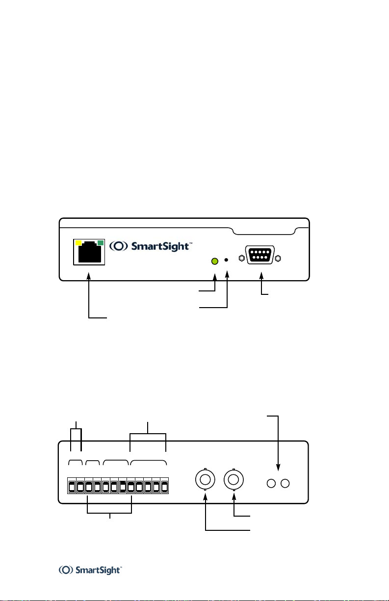
S1500e and S1502e
The front panel consists of:
An RJ-45 jack
A system status LED
A reset button
A female DB-9 connector for RS-232 use
S1500e Series
LAN 10/100
System status
RJ-45 Ethernet
Reset
Status
Reset
RS232
RS-232 serial port
(DB-9 connector)
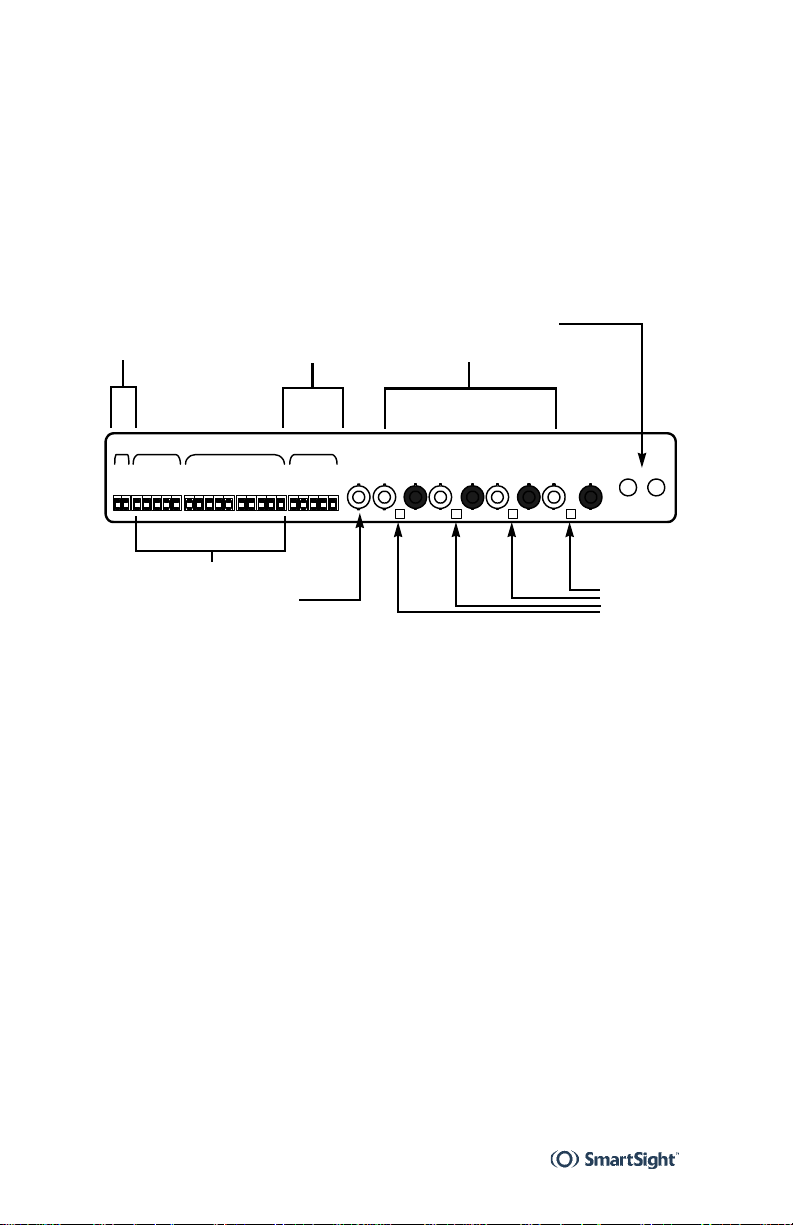
The back panel consists of:
A 12-pole connector for power, input/output, and
RS-422/485
One or two female BNC connectors to be used as video
input or output
Optional audio connectors
12V DC
Pwr
Gnd
Alarm/audio I/O
RS-422/485 serial port Audio (optional)
In
+12V
Out
Rly
Rly
RS422/485
In 1
In 3
In 2
Gnd
Tx+
Tx-
Rx+
Rx-
Video 2
Video 1
InOut
Video Audio
Main video
Video 2 for S1502e
5
1 Overview S1500e Series
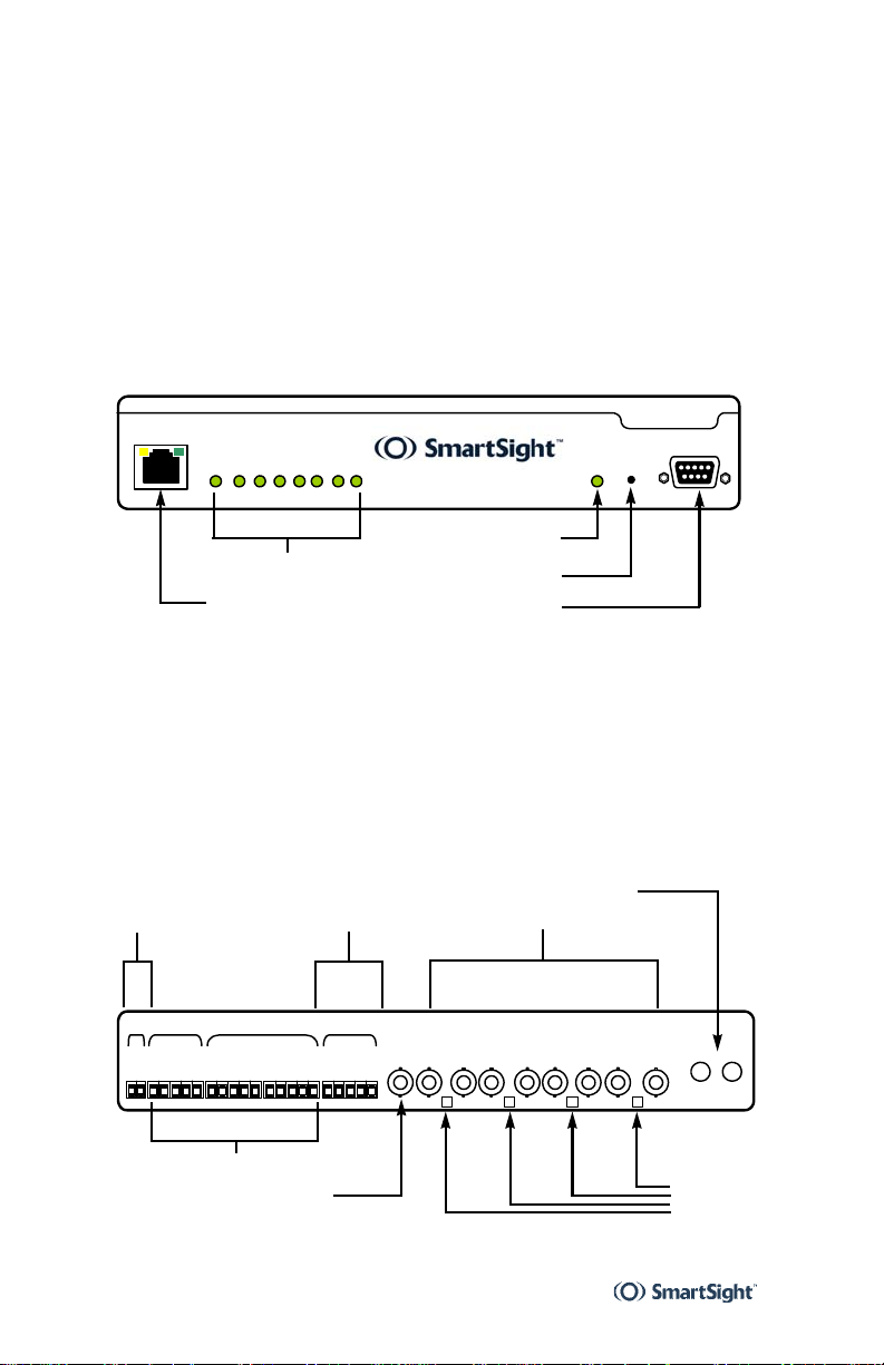
S1508e
The front panel consists of:
An RJ-45 jack
Eight video status LEDs
A system status LED
A reset button
A female DB-9 connector for RS-232 use
LAN 10/100
18765432
Video Status
S1508e
ResetStatus
System status
Video input status
RJ-45 Ethernet
RS-232 serial port
(DB-9 connector)
Reset
The back panel consists of:
Multipole connectors for power, input/output, and
RS-422/485
An optional video output BNC connector
Eight video input BNC connectors
Four DIP switches for the video input terminations
Optional audio connectors
Audio (optional)
12V DC
Pwr Out In RS422/485
Gnd
Rly 1
Rly 2
Rly 2
Rly 1
+12V
RS-422/485 serial port
In 1
In 3
In 2
Gnd
In 8
In 7
In 6
In 5
In 4
Gnd
Gnd
Video inputVideo input
Video out
Video in 1
Video in 2
Video in 3
Video in 4
Video in 5
Video in 6
Video in 7
Rx-
Gnd
Tx-
Tx+
Rx+
Video in 8
RS232
Out
In
Audio
Alarm/audio I/O
Video out (optional)
6
DIP
switches
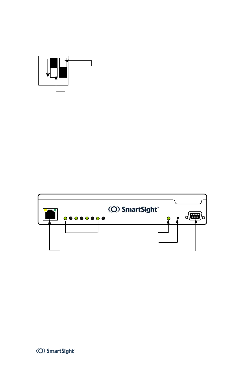
User Manual Unit Casing Description
The DIP switches determine if a video input is terminated in
the unit (with a load resistance of 75 ohms) or left in high
impedance for looping (hi-z).
Hi-z
ON 1 2
75 ohms
Position 1 is for the video input to the left of the switch,
whereas position 2 is for the video input to the right.
S1504e
The front panel consists of:
An RJ-45 jack
Four vi d e o s t a t u s L E D s
A system status LED
A reset button
A female DB-9 connector for RS-232 use
LAN 10/100
Video Status
1 2 3 45678
Video input status
RJ-45 Ethernet
System status
Reset
RS-232 serial port
(DB-9 connector)
S1504e
ResetStatus
RS232
Since the S1504e comes in the same casing as the S1508e,
eight video inputs are displayed. The four inputs used are
numbered 1, 3, 5, and 7.
7
1 Overview S1500e Series
The back panel consists of:
Multipole connectors for power, input/output, and
RS-422/485
An optional video output BNC connector
Eight video input BNC connectors
Four DIP switches for the video input terminations
Optional audio connectors
Audio (optional)
12V DC
Pwr Out In RS422/485
Gnd
Rly 1
Rly 2
Rly 1
+12V
RS-422/485 serial port
Rly 2
In 1
In 3
In 2
Gnd
In 8
In 7
In 6
In 5
In 4
Gnd
Video input
In
Video out
Video in 2
Video in 4
Video in 1
Rx-
Gnd
Tx-
Tx+
Rx+
Gnd
Video in 3
Video in 5
Video in 6
Video in 7
Video in 8
Out
Audio
Alarm/audio I/O
Video out (optional)
DIP
switches
In the DIP switches, only the left position is used.
8

Network Planning
To allow optimal configuration, you must properly plan your
network.
9
2 Network Planning S1500e Series
It is critical to ensure that no IP link of more than 300 feet
(100 meters) be present in a network, unless otherwise
stated by connection equipment such as 100Base-T to SC
converters, which can offer a 1.25-mile (2-km) range.
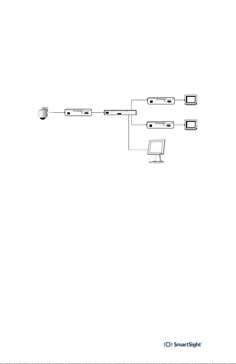
The S1500e supports a streaming method called multicast,
which permits more than one receiver unit to view a video
stream at any one time. Here is a typical connection for a
point-to-multipoint application.
Video source
Transmitter
Sw i t c h
Receiver
Receiver
nDVR Monitor
Monitor 1
Monitor 2
10

Configuring and Installing the Unit
To prepare your S1500e unit for operation, you have to
perform a series of steps:
Basic configuration, mainly for communication a nd serial
connection
Physical installation in its final location
Alarm and audio configuration
Connection to the serial ports
Remember that your unit is an indoor product that cannot
support an outdoor environment.
11

3 Configuring and Installing the Unit S1500e Series
Configuring the Unit
The following configuration steps are required:
Setting a series of parameters, including the IP address
In an analog extension context, perform ing
point-to-point connection
Computer Requirements
The minimum software and hardware requirements for the
computer needed to configure the unit are:
Windows 2000 Service Pack 2 or higher, or Windows XP
Network card
Serial port
Setting Unit Parameters
The first step in installing an S1500e system is to change
the IP address of the unit to ensure compatibility with an
existing network. The default IP addresses of all units are
based on the APIPA service and will be in the ra nge
169.254.X.Y, where X and Y are relative to the MAC address
of the individual unit; for more information about the APIPA
service, see page 47.
To work properly, units on the same network must have
unique IP addresses. The unit will not prevent you from
entering a duplicate address. However, its system status
LED will turn to flashing red; then the unit will reboot with
an APIPA address. If the unit is a receiver, the “Duplicate IP
Detected” message will also appear in the on-screen display
(for more information about this display, see Chapter 5,
page 39).
You can set the IP addresses of a unit by two methods:
Connecting your unit to the same LAN as the computer
running SConfigurator (described next)
Using the command line interface (see page 36)
Next, you have to set the serial port parameters of the unit.
12
User Manual Configuring the Unit
To set the parameters of a unit:
1 In a lab, unpack the unit and set it on a table.
2 Plug the S1500e IP connector directly to a computer
using a crossover cable or to your LAN using a
straight-through cable.
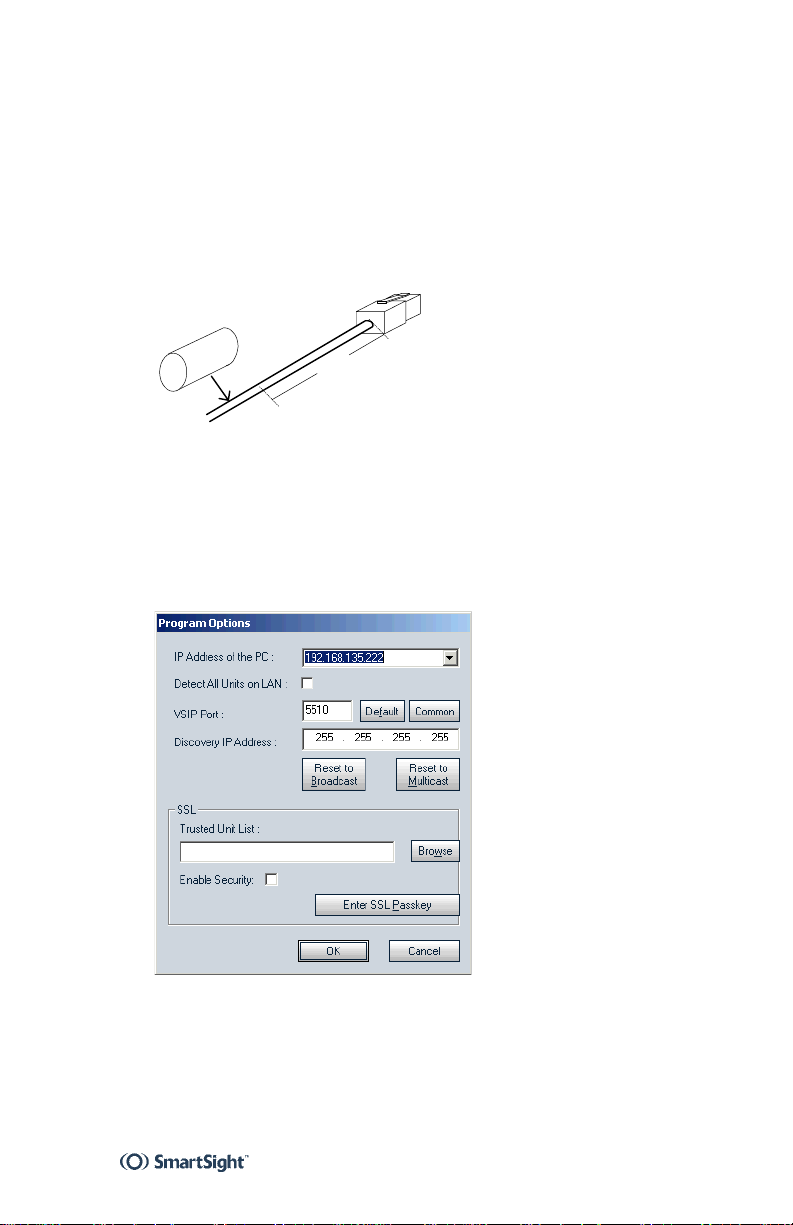
3 On the S1500e and S1502e only, install the ferrite
snap-on clamp on the Ethernet cable:
Ferrite
Clamp
2-3
inches
4 Powe r the u n it.
5 Start the SConfigurator software included on the
SmartSight Utilities CD shipped with your equipment.
The SConfigurator window appears.
6 From the General tab, click Program Options.
The Program Options window appears.
7 Ensure that the VSIP Port value is 5510; otherwise,
click Default.
8 Ensure that the Discovery IP Address is
255.255.255.255; otherwise, click Reset to Broadcast.
13
3 Configuring and Installing the Unit S1500e Series
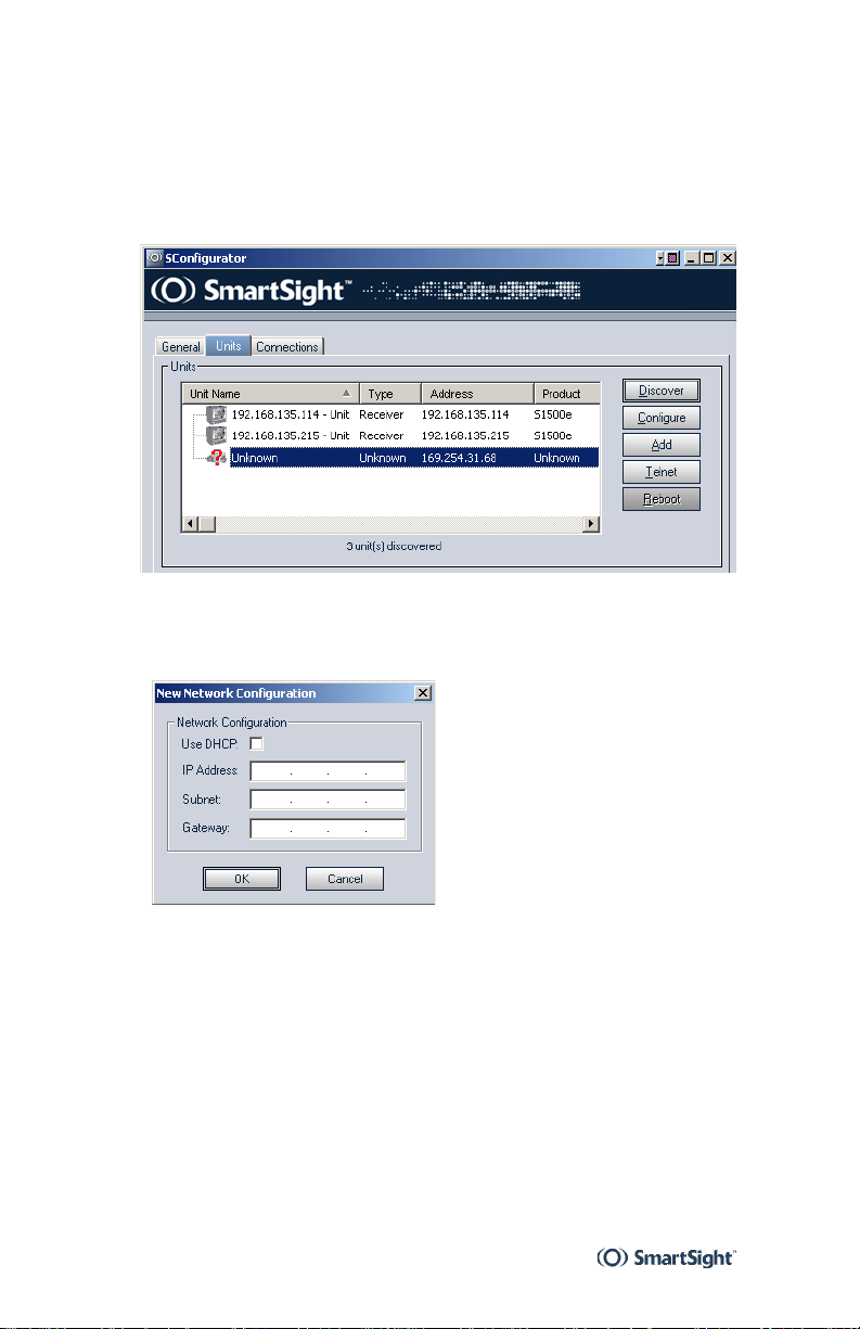
9 Check Detect All Units on LAN, then click OK.
10 Choose the Units tab, then click Discover.
A unit of type “Unknown” with a 169.254.X.Y IP address
appears in the list; it corr esponds to your new uni t.
11 Select the unknown unit, then click Configure. In the
Reconfigure unit? confirmation window, click Yes.
The New Network Configuration window appears.
12 To use DHCP (dynamic host configuration protocol),
check Use DHCP. Otherwise, enter the IP address,
subnet mask, and gateway of the unit, as provided by
your network administrator.
For more information about DHCP, see page 47.
13 Click OK.
The unit reboots with its new network configuration.
14 In the Units tab, click Discover.
The new S1500e unit appears.
14

User Manual Configuring the Unit
15 Select the unit, then click Configure.
16 Configure the serial port parameters to match those of
the target equipment (for instance, camera or PTZ
keyboard).
For more information, refer to the SConfigurator User
Manual.
The S1500e initial configuration is now complete. You
perform further configuration with either the SConfigurator
or nDVR software, both from SmartSight.
Performing a Point-to-Point Connection
To allow transfer of video, audio, I/O, and serial port data in
a point-to-point context (as opposed to using the nDVR
software), you have to create a connection between a
transmitter and a receiver. Typically, both units sit on the
same IP subnet as SConfigurator and have the same VS IP
port; to access othe r unit s, refer to the unit discovery
section in the SConfigurator User Manual.
Note
The two units must have the same firmware version, with the following
exception: The S1504e and S1508e, both at firmware release 3.0, will work
with an S1500e receiver at version 2.60.
For more information about the connection process, refer to
the “Managing Connections” chapter, also in the
SConfigurator User Manual.
To perform a point-to-point connection:
1 Start SConfigurator.
2 In the Units tab, discover the desired units.
The discovered units appear in the Units box.
15
3 Configuring and Installing the Unit S1500e Series
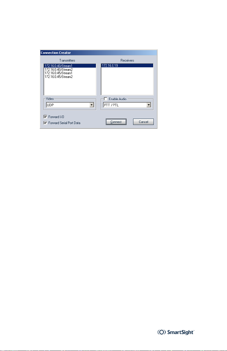
3 Choose the Connections tab, then click Add.
The Connection Creator window appears.
4 Select a transmitter in the left column and a receiver in
the right one.
5 To disable I/O data transmission (for example, alarms),
clear Forward I/O.
6 To disable serial port data transmission (like PTZ
commands), clear Forward Serial Port Data.
7 To enable audio, check Enable Audio, then select the
audio mode.
8 Click Connect.
You should now have video on the monitor connected to the
receiver unit.
16

User Manual Installing the Unit
Installing the Unit
Once your system is successfully configured, it is ready to be
installed in its final location.
The number of video inputs varies depending on the unit in
the S1500e series. Each source requires a means to output
the video. Depending on the context, you require up to eight
S1500e receivers to output the video:
Point-to-point analog extension—One receiver per video
input
nDVR—No receiver, since all output will be directed to
the computer screen
To install the system:
1 On the transmitter, plug the video cables of the domes
or cameras to the video connector s.
2 On an S1504e or S1508e unit, set the DIP switch for
each video input.
3 In a point-to-point context, plug each monito r video
input cable to an S1500e-R video connector.
4 Connect the RS-422/485 serial port of the unit to the
target device (for instructions, see page 18).
5 Plug the network cable to the RJ-45 Ethernet connector
on the unit.
6 When installing an S1500e-XT unit, make it stand
vertically, allowing for better cooling.
17
 Loading...