

SmartSight S1000-RX 1,S1000-RX 2,S1000-TX 1,S1000-TX 2,S1000-TX 3,S1000-RX 3 User Manual

S1000 USER MANUAL
(VERSION 0.33)
Instructions on how to configure,install
TM
and operate the SmartSight
For countries operating under
FCC Part 15 rules and regulation
1000 system
SmartSightTM Networks Inc.
1800 Berlier St.
www.smartsightnetworks.com
Suite 440
Laval, QC
H7L 4S4
Canada

ii
INFORMATION TO USER
This device complies with Part 15 of the FCC (Federal Communications Commission)
Rules (see http://www.fcc.gov/
). Operation is subject to the following two conditions: (1)
This device may not cause harmful interference, and (2) This device must accept any
interference received, including interference that may cause undesired operation.
This equipment has been tested and found to comply with the limits for Class B Digital
Device, pursuant to Part 15 of the FCC Rules. These limits are designed to provide
reasonable protection against harmful interference in residential installation. This
equipment generates and can radiate radio frequency energy and, if not installed and used
in accordance with the instructions, may cause harmful interference to radio
communications. However, there is no guarantee that interference will not occur in a
particular installation. If this equipment does cause harmful interference to radio or
television reception, which can be determined by turning the equipment off and on, the
user is encouraged to try to correct the interference by one or more of the following
measures:
• Reorient or relocate the receiving antenna
• Increase the separation between the equipment and S1000 module
• Connect the equipment into an outlet on a circuit different from that to which the
Receiver is connected
• Consult the dealer or an experienced radio/TV technician for help
Any changes or modifications not expressly approved by SmartSight Networks could void
the user’s authority to operate the equipment.
SMARTSIGHT is a trademark of SmartSight Networks, Inc.
Copyright © 2001 SmartSight Networks, inc., Laval, Quebec, -All rights reserved.

iii
WARRANTY
Each standard product manufactured by SmartSight™ Networks is warranted to meet all
published specifications and to be free from defects in material and workmanship for a
period of one (1) year from date of delivery as evidenced by SmartSight™ Networks
packing slip or other transportation receipt. Products showing damage by misuse,
abnormal conditions of operation or products which have been modified by Buyer or have
been repaired or altered outside SmartSight™ Networks factory without a specific
authorization from SmartSight™ Networks shall be excluded from this warranty.
SmartSight™ Networks shall in no event be responsible for incidental or consequential
damages including without limitation, personal injury or property damage.
SmartSight™ Networks responsibility under this warranty shall be to repair or replace, at
its option, defective work or parts returned to SmartSight™ Networks with transportation
charges to SmartSight™ Networks factory paid by Buyer and return paid by SmartSight™
Networks. If SmartSight™ Networks determines that the Product is not defective within
the terms of the warranty, Buyer shall pay all costs of handling and transportation.
SmartSight™ Networks may, at its option, elect to correct any warranty defects by sending
its supervisory or technical representative, at SmartSight™ Networks expense, to
customer’s plant or location. SmartSight™ Networks shall in no event be responsible for
incidental or consequential damages including, without limitation, personal injury or
property damage.
SINCE SMARTSIGHT™ NETWORKS HAS NO CONTROL OVER CONDITIONS OF
USE, NO WARRANTY IS MADE OR IMPLIED AS TO SUITABILITY FOR CUSTOMER’S
INTENDED USE. THERE ARE NO WARRANTIES, EXPRESSED OR IMPLIED,
EXCEPT AS STATED HEREIN. This limitation on warranties shall not be modified by
verbal representations.
Equipment shipped EX-Works SmartSight™ Networks factory shall become the property
of Buyer, upon transfer to the common carrier. Buyer shall communicate directly with the
carrier by immediately requesting carrier’s inspection upon evidence of damage in
shipment.
Buyer must obtain a Return Materials Authorization (RMA) number and shipping
instructions from SmartSight™ Networks prior to returning any Product under warranty.
DO NOT RETURN ANY SMARTSIGHT™ NETWORKS PRODUCT TO THE FACTORY
UNTIL RMA AND SHIPPING INSTRUCTIONS ARE RECEIVED.
SmartSightTM 1000 User Manual / Rev 0.33
iv
Customer Support
If after reading this manual, you encounter any trouble installing or using any
SmartSight™ product, please contact your local distributor or SmartSight representative.
If problems are not solved, we will be glad to assist you directly. You can call
SmartSight™ Networks Customer Service for assistance during normal business hours.
The fax and phone numbers are:
Ph: 450-686-9000 (Canada) and 888-494-7337 (North America)
Fax: 450-686-0198
You may also e-mail your inquiries and comments at the following address:
techsupport@smartsightnetworks.com
About this User Manual
This User’s Manual covers the information and procedures on installing, configuring and
using the SmartSight™ 1000 modules. This manual is also a reference for persons who
must perform or coordinate tasks associated with programming and managing the
SmartSight™ 1000 system.
Pan-Tilt-Zoom functions to be controlled through the use of a 3
be discussed in this manual. While this user manual will give detailed information on how
to configure the SmartSight™ 1000 for use with any keyboard/PTZ (Pan-Tilt-Zoom)
platform, knowledge of the setup of these keyboard/PTZ platforms remains the
responsibility of the end user.
Prerequisite Knowledge
Throughout the user's manual there are explanations and procedures that presume
working familiarity with radios, as well as basic digital data communication concepts and
practices, and an understanding of the concepts underlying telecommunication systems.
If you are not familiar with the concepts and practices involved in these disciplines, we
recommend that you familiarize yourself with them before proceeding.
Manual Conventions
Suggestion
rd
party keyboard shall not
Note
Warning

v
TABLE OF CONTENT
CHAPTER 1 OVERVIEW..................................................................................................... 1
1.1 PRODUCT..................................................................................................................... 1
1.2 EQUIPMENT.................................................................................................................. 1
CHAPTER 2 S1000 SYSTEM SETUP GUIDE ..................................................................... 2
2.1 EXTERNAL MODULE DESCRIPTION .................................................................................. 2
2.2 APPLICATIONS .............................................................................................................. 3
CHAPTER 3 S1000 SYSTEM CONFIGURATION AND INSTALLATION............................ 4
3.1 S1000 SYSTEM CONFIGURATION ................................................................................... 4
3.2 UNDERSTANDING THE STATUS LED................................................................................. 5
3.3 S1000 SYSTEM INSTALLATION ....................................................................................... 6
CHAPTER 4 PROPER RF AND NETWORK PLANNING .................................................... 9
4.1 NETWORK PLANNING .................................................................................................... 9
4.1.1 Co-locating up to 3 systems ................................................................................ 9
4.1.2 Co-locating up to 6 systems (360 degree coverage) ........................................... 9
4.1.3 Co-locating up to 6 systems (less than 180 degree coverage) .......................... 11
4.1.4 Co-locating systems on different sides of a building .......................................... 12
4.2 RF PLANNING............................................................................................................. 13
4.2.1 Evaluation of the location .................................................................................. 13
4.2.2 Evaluation of antenna requirements.................................................................. 14
4.2.3 Coping with Interference ................................................................................... 14
4.2.4 RF Exposure Considerations............................................................................. 15
CHAPTER 5 USING THE COMMAND LINE INTERFACE TO PROGRAM THE S1000 .... 16
5.1 RESET TO FACTORY DEFAULT ...................................................................................... 16
5.2 HYPER TERMINAL ....................................................................................................... 16
5.2.1 Starting the Hyper Terminal from Windows 98 .................................................. 17
5.2.2 Configuring Hyper Terminal............................................................................... 18
5.3 S1000 CLI................................................................................................................. 19
5.3.1 Starting the CLI ................................................................................................. 19
5.3.2 Using the CLI .................................................................................................... 20
5.4 SERIAL PORT SETUP ................................................................................................... 20
5.4.1 Bit rate............................................................................................................... 20
5.4.2 Parity................................................................................................................. 20
5.5 RF COMMUNICATIONS SETUP ...................................................................................... 21
5.5.1 RF channel........................................................................................................ 21
5.5.2 SSID ................................................................................................................. 21
5.5.3 Bit rate............................................................................................................... 21
5.5.4 WEP Key........................................................................................................... 21
5.5.5 WEP Encryption activation ................................................................................ 22
5.6 VIDEO SETTINGS SETUP .............................................................................................. 22
5.6.1 Target frame rate .............................................................................................. 22
5.6.2 Set target bit rate............................................................................................... 22
5.6.3 Video standard: PAL / NTSC............................................................................. 22
CHAPTER 6 UPGRADING THE S1000 FIRMWARE......................................................... 23
6.1 STARTING THE SMARTSIGHT
TM
MANAGEMENT INTERFACE............................................. 23
6.2 PERFORMING A FIRMWARE UPLOAD............................................................................. 23
SmartSightTM 1000 User Manual / Rev 0.33

vi
LIST OF FIGURES
IGURE 1 S1000 – EXTERNAL VIEW.......................................................................................... 2
F
FIGURE 2 EXAMPLE OF A POLE MOUNT INSTALLATION................................................................. 8
FIGURE 3 CROSS-SECTION VIEW OF S1000-RX ANTENNAS AROUND......................................... 10
FIGURE 4 EXAMPLE OF CO-LOCATED SYSTEMS WITH EACH 2 SYSTEMS SHARING ONE CHANNEL .. 12
FIGURE 5 DIFFERENCE BETWEEN FRESNEL ZONE AND VISUAL LINE OF SIGHT........................... 14
FIGURE 6 STARTING HYPER TERMINAL FROM WINDOWS 98...................................................... 17
FIGURE 7 HYPER TERMINAL STARTUP SCREEN ........................................................................ 18
FIGURE 8 HYPER TERMINAL CONFIGURATION WINDOW ............................................................. 19
FIGURE 9 CLI START UP SCREEN ............................................................................................ 20
FIGURE 10 SMI START UP SCREEN ....................................................................................... 23
FIGURE 11 SCREEN SHOT BEFORE A FIRMWARE UPLOAD ........................................................ 24
FIGURE 12 SERIAL PORT CONFIGURATION WINDOW .............................................................. 25

1
CHAPTER 1 Overview
1.1 Product
The SmartSight™ 1000 is a professional video transmission product designed for the
CCTV (Closed Circuit Television) market. It offers a secure (encrypted using a Wired
Equivalent Privacy algorithm) signal 100 times more robust to interference than
conventional AM/FM analog systems. The system consists of a video transmitter
(S1000-TX) and a video receiver (S1000-RX).
1.2 Equipment
Your S1000 shipment should contain the following items:
• 2 - S1000 or S1000-24VAC modules (S1000-TX & S1000-RX)
• 2 - wall mounting bracket set
• 2 cable assemblies (P/N S1000-CA-9P)
• User’s manual.
The shipment may also contain the following options:
• 1 or 2 16 dBi gain antennas (S1000-PA)
• 1 or 2 15 VDC external power supply (S1000-PS)
• 1 or 2 Pole mount bracket sets (S1000-PM)
• 1 or 2 Junction Box with 24 VAC input (S1000-JB).
• 1 or 2 optional alarm/audio cable assemblies (P/N S1000-CA-8P)
___________________________________________________________________
If you have not ordered a power supply option (S1000-PS or S1000-JB) you will need to
supply a 12-15 VDC power supply to each module (or 24 VAC if you have ordered the
S1000-24VAC system). We recommend using a power supply with a capacity of 8 watts or
more.
___________________________________________________________________
___________________________________________________________________
Check the material against the packing list to make sure you have received everything. If
something is missing or if you discover shipping damage, please contact your dealer or
distributor.
___________________________________________________________________
SmartSightTM 1000 User Manual / Rev 0.33
2
CHAPTER 2 S1000 system setup guide
The S1000 is to be professionally installed. The guidelines in the following subsections
will assist the installer in cabling and installing the Microflex.
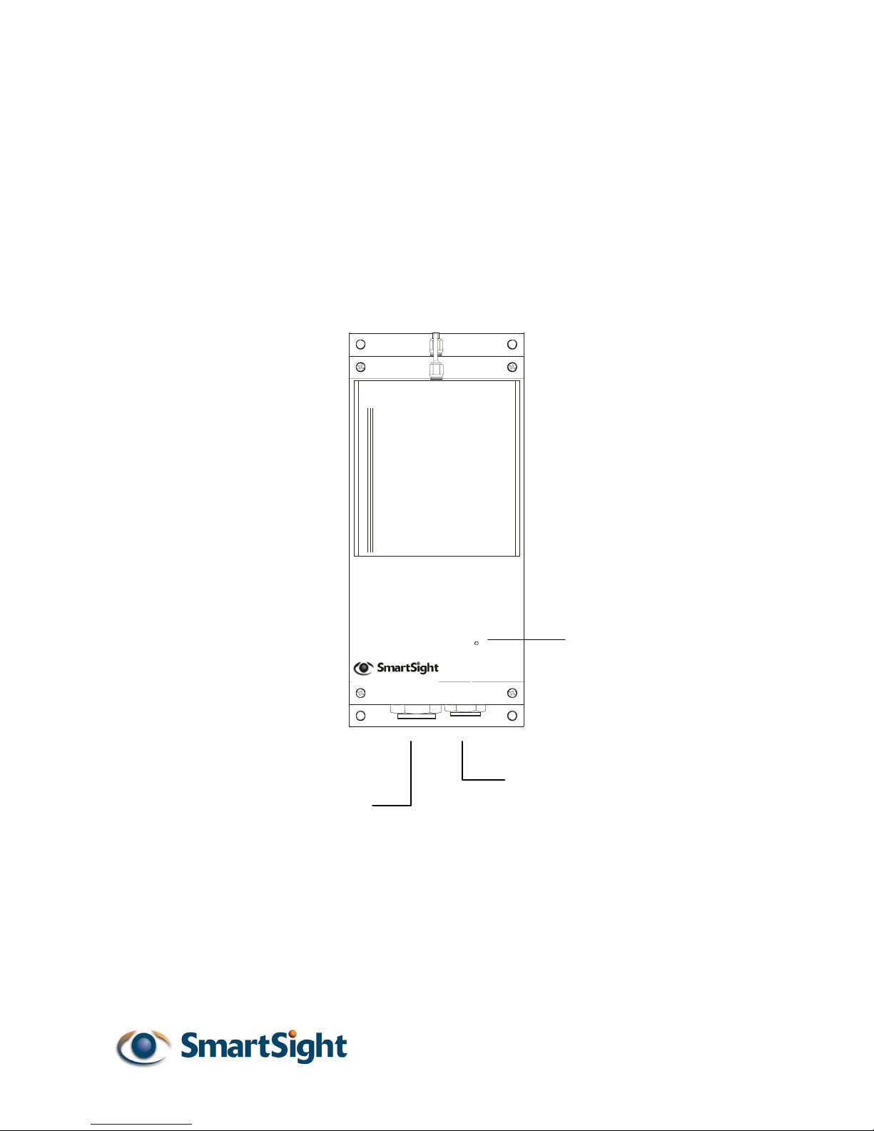
2.1 External module description
The S1000 (Transmitter) is labeled “Tx” and the S1000 (Receiver) is labeled “Rx”.
Stat us
TM
Status indicator
Auxiliary connector
(Alarm I/O and Audio)
Main connector
(Video, Power
and Serial Port)
Figure 1 S1000 – External view.
The S1000 electronics are enclosed in a weather-tight cast aluminum module. All
cable entries are mounted on the underside of the module to maintain its weathertight properties. The front panel of the S1000 integrates one bi-color visual indicator
that indicates the module operational state.

3
2.2 Applications
The current software version of the S1000 supports operation in point-to-point.
Future software upgrades will support transmission of video to multiple receivers as
well as retransmission of signal in none-line-of-sight application.
The S1000 supports 3 non-overlapping channels (channels 1, 6 and 11) or
operation of 3 simultaneous links within the same location. It is also possible to
support up to 6 links simultaneously with each of the six receivers installed at the
same location. However, this requires some site planning (see CHAPTER 4).
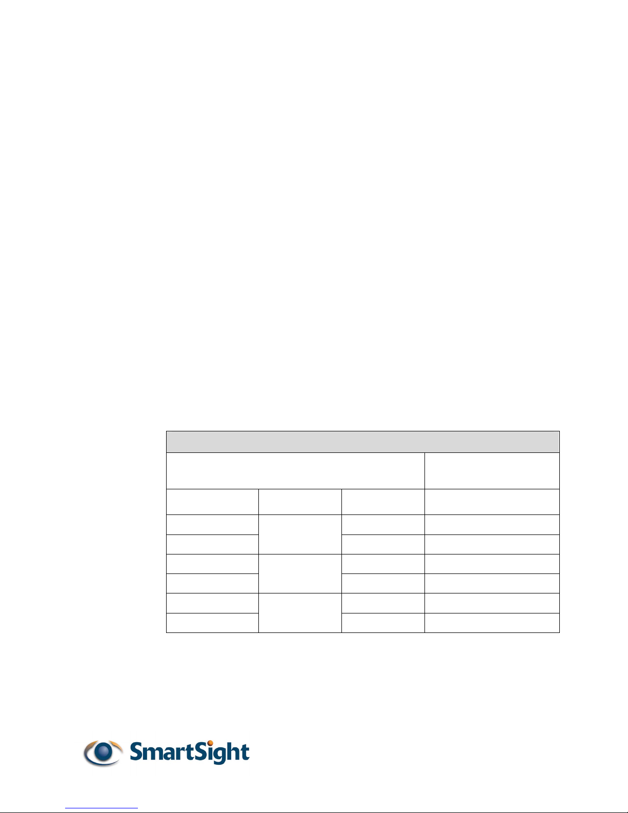
In most case, you will need to program a unique SSID (security ID) for each radio
system (see 4.2.4 to learn how to configure each module using a computer). As an
example, for 3 S1000 systems, 3 individual SSID are required. The table below
shows the configuration applied to each module:
Module Configured Channel Configured SSID
S1000-TX 1 1 SYSTEMA
S1000-RX 1 1 SYSTEMA
S1000-TX 2 6 SYSTEMB
S1000-RX 2 6 SYSTEMB
S1000-TX 3 11 SYSTEMC
S1000-RX 3 11 SYSTEMC
SmartSightTM 1000 User Manual / Rev 0.33
4
CHAPTER 3 S1000 System Configuration and Installation
3.1 S1000 system configuration
Your S1000 system is configured to operate right out of the box with the most
popular dome data port configurations (4800 baud, 8 data bits, no parity, 1 stop bit).
For added security, we recommend you change the SSID to your own secret SSID
and activate the WEP encryption and change the WEP key to your secret WEP key
before installing the system.
STEP 1 Initial Configuration
• Unpack the modules and set them side by side on a desk or table.
• Unpack the 2 cable assemblies (P/N S1000-CA-9P) and connect them to the
module (you must feel a positive click for the cable assembly connector to be
properly installed on the module)
• Connect the S1000-TX cable assembly DB-9 to a computer (if the DB9 has
been removed, refer to the table below to connect conductors properly) and
power the module (the STATUS LED should turn steady green and then
flashing green under normal operation; see the next section to understand
how this LED behaves under different operation conditions)
S1000-CA-9P TO PC CONNECTION
S1000 Cable Assembly Serial Port Description
(DCE port)
SIGNAL NAME WIRE PAIR WIRE COLOR SIGNAL NAME
CTS
RxD
TxD
RTS
Signal GND
Signal GND
GREEN/
BLACK
YELLOW/
BLACK
BROWN/
BLACK
GREEN Not used
BLACK RX
YELLOW TX
BLACK Not used
BROWN Signal GND
BLACK
Computer
(DTE)
Signal GND
NOTE: Power the unit via the cable assembly RED & BLACK conductor
pair. The RED conductor is for 12 VDC input (or 24VAC if this
option was purchased) and the BLACK conductor is for the power
GROUND (or 24 VAC return if this option was selected).

5
• Configure the S1000-TX SSID, WEP encryption key (if desired), radio
channel and serial port parameters (if required) via the computer (see 4.2.4
for configuration procedure)
• Connect the S1000-RX cable assembly DB-9 to the computer and power the
module (the STATUS LED should turn steady green under normal operation;
see the next section to understand how this LED behaves under different
operation conditions).
• Configure the S1000-RX parameters to the SAME parameters configured on
the S1000-TX
• You have completed the S1000 initial configuration. The system can now be
installed outdoors.
___________________________________________________________________
The S1000 integrates a single serial port. This port is used for both system configuration and data
communications (PTZ, access control or other). The serial port on the S1000 automatically detects
if it is connected to a computer (RS-232 serial port) or an RS-422 serial device. The user does not
have to configure the serial port for RS-232 or RS-422/485 operation or for configuration or data
communications.
__________________________________________________________________
3.2 Understanding the status led
The STATUS LED is a bi-color (GREEN-RED) LED which provides detailed
information on the system depending on whether the system is powering up, in
operation or the software is being updated.
Power-up sequence:
• Flashing Red (module is powering up)
• Steady Green (Application is started).
___________________________________________________________________
In very cold weather, the powering up sequence may take several minutes (up to 15 minutes at –
30°C). This is because the module must reach a certain internal temperature before powering up all
the electronics.
___________________________________________________________________
___________________________________________________________________
The following power-up conditions are abnormal:
1) LED not lit: Check the power supply and cabling, if power is available and the LED
stays off, call SmartSight technical support to obtain an RMA authorization.
2) Steady RED LED: There is an internal module error that prevents the unit from
SmartSightTM 1000 User Manual / Rev 0.33
 Loading...