

Page 1
SZ936-2009.10.16
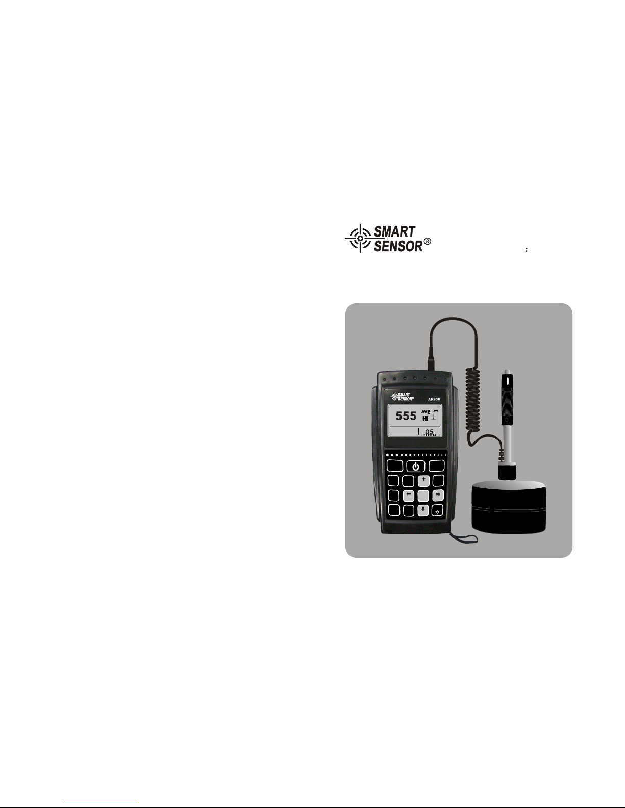
Operation Manual of
Leeb Hardness Tester
Model AR936
555555
VV
A A
EE
Hl Hl
Portable Hardness Tester
Steel and cast steelSteel and cast steel
9
3
0
7
8
2
1
4
6
5
STORE
ENTER
9
3
DEL
0
DIR
7
AVE
8
HARD-
NESS
2
ESC
MAT’L
1
TIMES
4
MENU
6
5
Page 2

special notice
Turn off the unit before replacement
of battery impact device!
Page 3
Content
rief
-----------------------------------------------( 9 )before operation
requirements on the measured -------------------------------( 9 )
system setting ------------------------------------------------(10)
measuring condition setting ------ ---------------------------(10)
measuring method --------------------------------------------(10)
Working principle and Diagram of the instrument
4.O
peration
Working principle --------------------------------------------(05)
Diagram of the instrument------------------------------------(06)
hardness tester -----------------------------------------------(06)
Main unit ------------------------------------------------------(07)
d type impact device ---------------------------------------- (07)
irregular type impact device-------------------------------- (08)
3.Technical features
--------------------------------------------------------(04)features
application and its range -------------------------------------(04)
application----------------------------------------------------(04)
application range -------------------------------------------- (04)
model specifications -----------------------------------------(05)
operation condition------------------------------------------(05)
Starting ------------------------------------------- ------ -(10)-----
Load ---------------- ------ ------------------------------ -------(10)
Placement ------------------------------ ------------ (10) ---------- -
Measuring - ------------ ----------------------------------------(10)
-01-
Maintenance and warranty
1D
Maintenance
put
Warranty
warranty
. o not the instrument under the following environment:
a. In risk of splash by water or highly intense dusy environment
b. Air of high content of salt or sulfurate
c. Air of othere chemical substance
d. High humidity and temperature(above 60 90%RH) or in sunlight
2. Don't disassemble the instrument or change the inner struction
3. Alcohol and diluent is erosive to the LCD, clean the housing with cloth
of slight water.
1. Refer to the terms in the card
2. Any damage res ulting from unauthorized dismantle of the unit,
improper transport or storage in breach of the manual instruction
as well as unauthorized amendment of guarantee card or lack of
proof will lead to refusal of guarantee service.
D
a.
eclaration:
The battery used must be dealt with according to the local laws,
rules and regulatoins.
b. Our company reserve the right to upgrade and amend the
specifications and design of the instrument and instructions,
they are subject to change without further notification if any.
-28-
Other Items
Page 4
-02-
-------------------------------------------(15)impact direction setting
average times setting -----------------------------------------------(15)
----------------------------------------- -- (15)material setting ---------
hardness setting ---------------------------------------------------- -(16)
tolorence setting ---------- -------------------------------------- --- (16)
hardness/intensity setting - ----------------------------------------- (16)
storage management --- ------------------------------------------ --(16)
review from first group to the last ------------- (17)-------------- ------
reviewing the selected ------- (17)-------------------------------- -------
data transmission ------- --------------------------------------- -----(17)
deleting the selected ----------------------------------------- -------(17)
delete all ----------------- ---------------------------------------- ----(17)
confirm of deletion -------------------------------------- ----------- (18)
data review ------------- ------------------------------------------ -- -(18)
system review ---------- ------------------------------------------- -- (19)
LCD brightness setting --------------------------------------- ------(19)
6.D
etails on operation
-------------------------------------------------------------- (12)turn on
turn off --------------------------------------------------------------(12)
measurement -------------------------------------------------------(12)
main menu-----------------------------------------------------------(13)
measuring operation------------------------------------------------(13)
buttons --------------------------------------------------------------(13)
menu tree ------------------------------------------------------------(14)
measuring condition setting ---------------------------------------(14)
pick up value --------------------------------------------------------(11)
turn off ----------- -------------------------------------------------- -- (11)
5.Special instruction
User notice
1 After purchase of this unit, the user is expected to fill in the guarantee
card with unit stamp, then deliver its copy along with the invoice copy
to our customer service center, or ask the distributor to do so.
Incomplete proof will lead to maintenance without guarantee.
2 The instrument enjoys one year guarantee service since the purchase
of the unit, in this period if there is any malfunction, against the
guarantee card or invoice, contact our service center for free charge
service. In case no guarantee card or invoice be presented our
company will calculate the guarantee period since the date off factory.
3 Beyond the guarantee period, the maintenance will be charged by our
service department.
4 The components like(irregular type , enlonged
cable, specialized software etc.) will be charged accordingly.
optional impact device
5 Any damage resulting from unauthorized dismantle of the unit,
improper transport or storage in breach of the manual instruction as
well as unauthorized amendment of guarantee card or lack of proof
will lead to refusal of guarantee service.
6 Please follow the manual instruction to operate, if there is any
malfunction, contact our company immediately.
-27-
Page 5
----------------------------------- (22)maintenance impact device -
instrument maitenance -- (22)--------------------------------------- -
instrument check-------------------------------------------------(22)
notice of storage and transport --------- - ------------------ ----- (22)
system calibration -- (20)-------------------------------------------- -
program infomation - (20)----------------------------------- ---------
Backlight ----- (21)--------------------------------------------------- -
automatical turn off (21)---------------------------------------------
battery replacement (21) ---------------------------------------------
connection of data cable (21) ----------------------------------------
7.Trouble shooting
8.U
pkeep and maintenance
A
ppendix
apeendix two - ---(24)-------------------------------------- ----------
appendix one -- - - (23)----------------------------------------- --- -- --
apeendix three - -- (25)----------------------------------------------- -
apeendix four- - - -- (26)----------------------------------------- - -- ---
notice for user - ------------- --------------------------------- --- (27)
-03-
maintenance and warranty-- --------------------------------- ---(28)
Appendix 4
-26-
time/date setting ---------------------------------------------------(20)
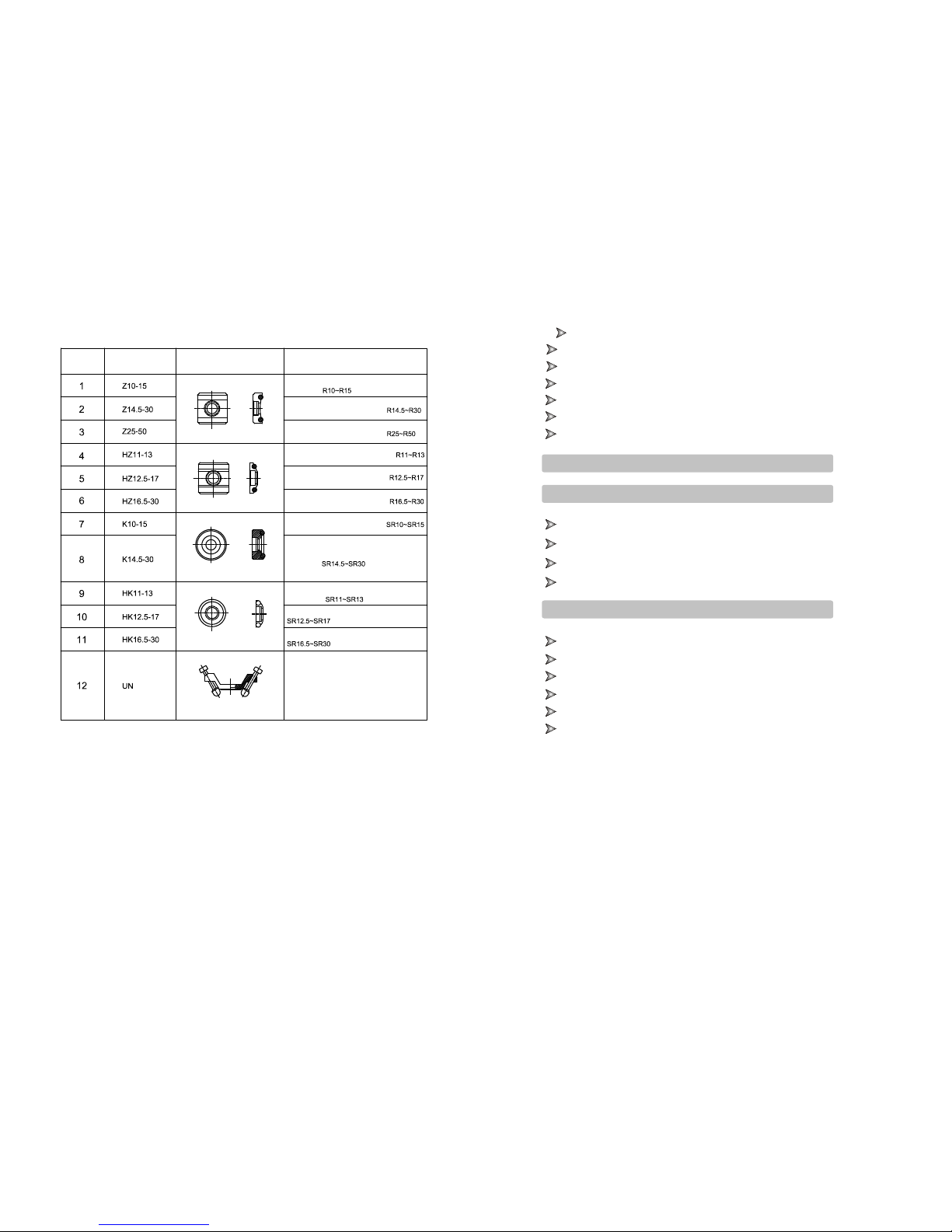
No
Model
Sketch of support ring
Remarks
for testing cylindrical outside
surface
inner cylindrical surface
for testing cylindrical outside
surface, radius adjustable R10-8
out cylindrical surface
out cylindrical surface
inner cylindrical surface
inner cylindrical surface
out cylindrical surface
or testing spherical outside
surface
for testing spherical inside
surface
inner cylindrical surface
inner cylindrical surface
Page 6
-04-
1 Brief
1.1Features
l Adopting Leeb hardness measuring principle, this unit can test the hardness of
most metals.
l 160*80 lattice LCD display allows complete information and clear reading.Large
l All display with menu indication makes the operation easy and convenient.English
l Alternative white backlight display and USB plug facilitate the opeation in darkness
and communication with PC for data exchange and configuration.
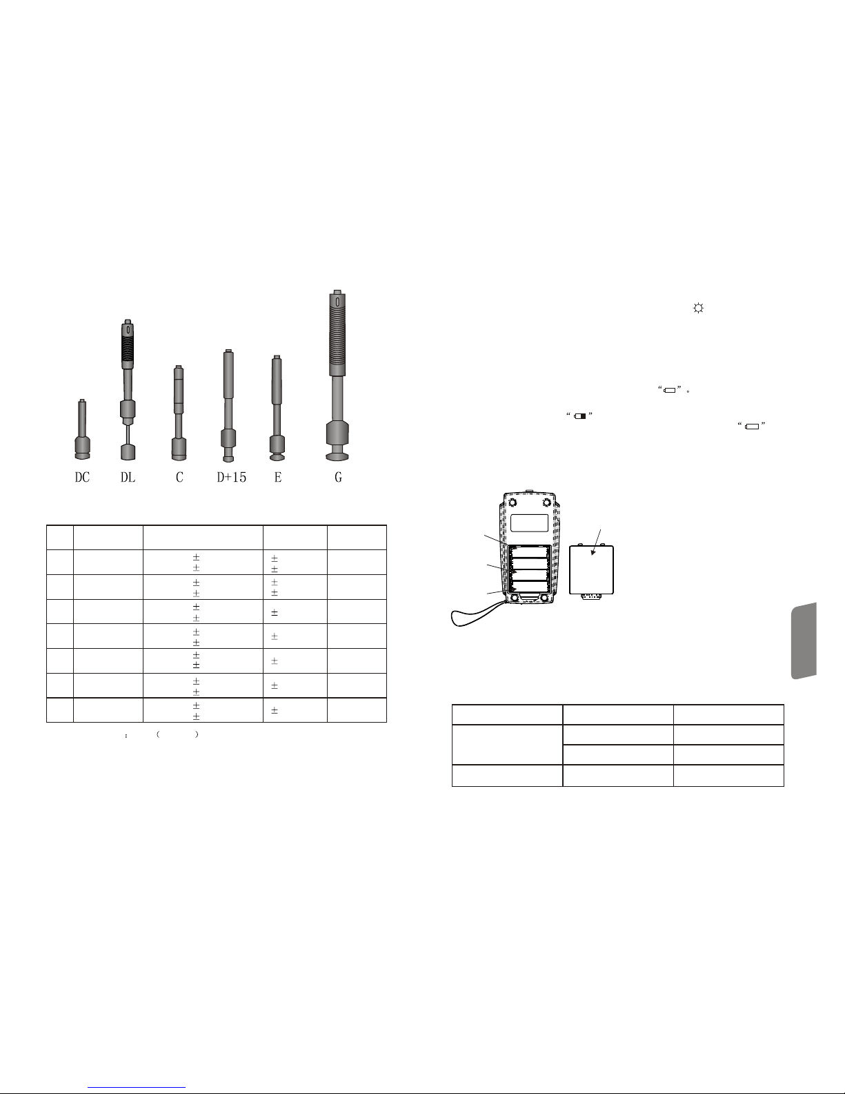
l The is matchable with 7 striking fittings, capable of identifying the striking
type automatically, and requires no further calibration after replacement.
main unit
l The unit can store up to 500 groups of date( times 32~1), in which each group
contains information of single value, average value, measuring date,
direction, times, material and hardness unit.
impact
impact
impact
l With presetting of up and low limits, the unit alarm automatically if reading is
beyond the limits, which facilitates massive measurement.
l Battery volume icon on LCD indicates the and calibratable with
software.
battery power
l When using D/DC type for steel material hardness testing,
the reading can be displayed directly without consultation of the table.
impact device
l Equipped with PC program, this software supports transmission of the measuring
results, storage management, statistical analyzing, print and massive parameters
setting to ensure higher quality and management.
l Professional and nice outline, smart, portable and reliable performace makes the unit
operatable in rough environment, and immune from vibration, striking and
elecmagnetic interference.
l 4 AA alkaline batteries support continuous operation for more than 50 hrs.
and automatical turn off function.
l 150*80*38mmProduct Dimension
1.2 Application and range
1.2.1 Application
l Tooling cavity
l Bearing and other workpiece.
l Pressure vessel, steam generator and its failure analysis.
l Heavy workpiece.
l Amounted machanism and permanent assembly.
l Workpiece with small testing space.
l Original record of testing results required.
l Division of metal material warehouse.
l Quick test for many locations on large workpiece.
1.2.2 Measuring range
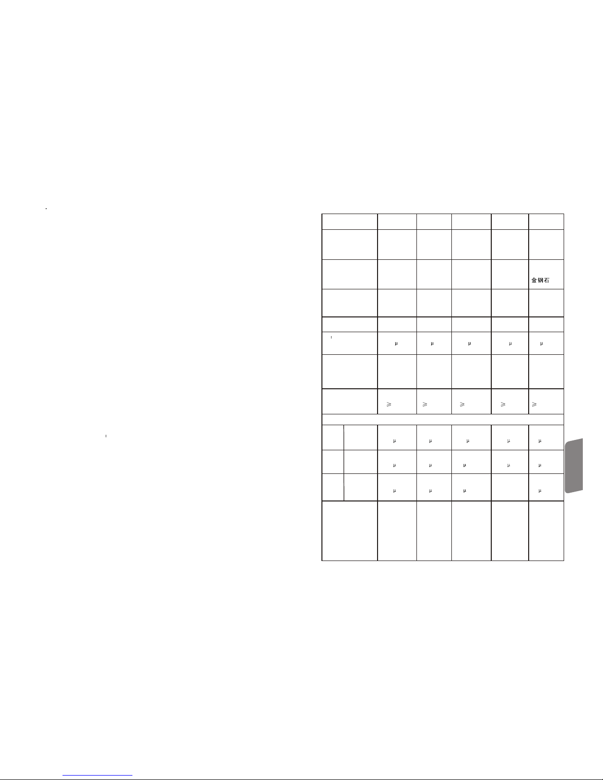
see appendix one and two.
Appendix 3
impact device
DC(D)/DL
D+15
C G
E
impacting energy
and mass of
impact body
11mJ
5.5g/7.2g
11mJ
7.8g
2.7mJ
3.0g
90mJ
20.0g
11MJ
5.5g
ball hardness
ball diameter
ball material
1600HV
3mm
carbonized
tungsten
1600HV
3mm
1600HV
3mm
1600HV
5mm
5000HV
3mm
Diameter of
length of
weitht
of
impact
device
impact device
impact device
20mm
86(147)/
75mm
50g
20mm
162mm
80g
20mm
141mm
75g
30mm
254mm
250g
20mm
155mm
80g
max hardness
of workpiece
940HV 940HV 1000HV
650HB
1200HV
Ra average
roughness of
workpiece
1.6 m 1.6 m 0.4 m 6.3 m 1.6 m
min weight of workpiec
direct measure requires
solid support
and intense coupling
>5kg
2~5kg
0.05
2kg
>5kg
2~5kg
0.05~2kg
>1.5kg
0.5~1.5kg
0.02~0.5kg
>15kg
5~15kg
0.5~5kg
>5kg
2~5kg
0.05~2kg
min thickness of
workpiece
intense coupling
min depth of
rigidified layer
5mm
0.8mm
5mm
0.8mm
1mm
0.2mm
10mm
1.2mm
5mm
0.8mm
hardness
300
hv hour
indentation
diameter
indentation
depth
0.54mm
24 m
0.54mm
24 m
0.38mm
12 m
1.03mm
53 m
0.54mm
24 m
hardness
600
hv hour
0.54mm
17 m
0.54mm
17 m
0.32mm
8m
0.90mm
41 m
0.54mm
17 m
hardness
800
hv hour
0.35mm
10 m
0.35mm
10 m
0.35mm
7m
--
--
0.35mm
10 m
application range
of impact device
DC type for
hole or cylinder.
DL type for long
and narrow
channel or hole
D type for
general peices
test
D+15 type for
measuring in
grooves or
recessed
surfaces
C type for
measuring
light and small
piece and
surface
hardened layer
G type for for
measuring he
avy and rough
cast and forged
pieces
E type for
high
hardness
material
size of ball impress
-25-
impress
diameter
impress
depth
impress
diameter
impress
depth
Operation
Explanations
Page 7
-05-
1.4 Operating condition
environment temp operating temp-20~+60 storage temp -30 ~+60
relative humidity 90%
Do not use the instrument in strong vibration, magnetic field, erosive substance and
high density powder and dust codictions.
2 Working principle and Diagram of the instrument
2.1 Working principle
An impact body with a spherical test tip made of
tungsten carbide is propelled against the sample
surface by a spring force and then rebounds back.
At a distance of 1mm from the sample surface, the
impact and rebound velocity of the impact body,
when passing through the coil in its coiler holder,
induces in the coil and electric voltage proportional
to the velocities fo the magnet. Leeb hardness as the
follo wing formula:
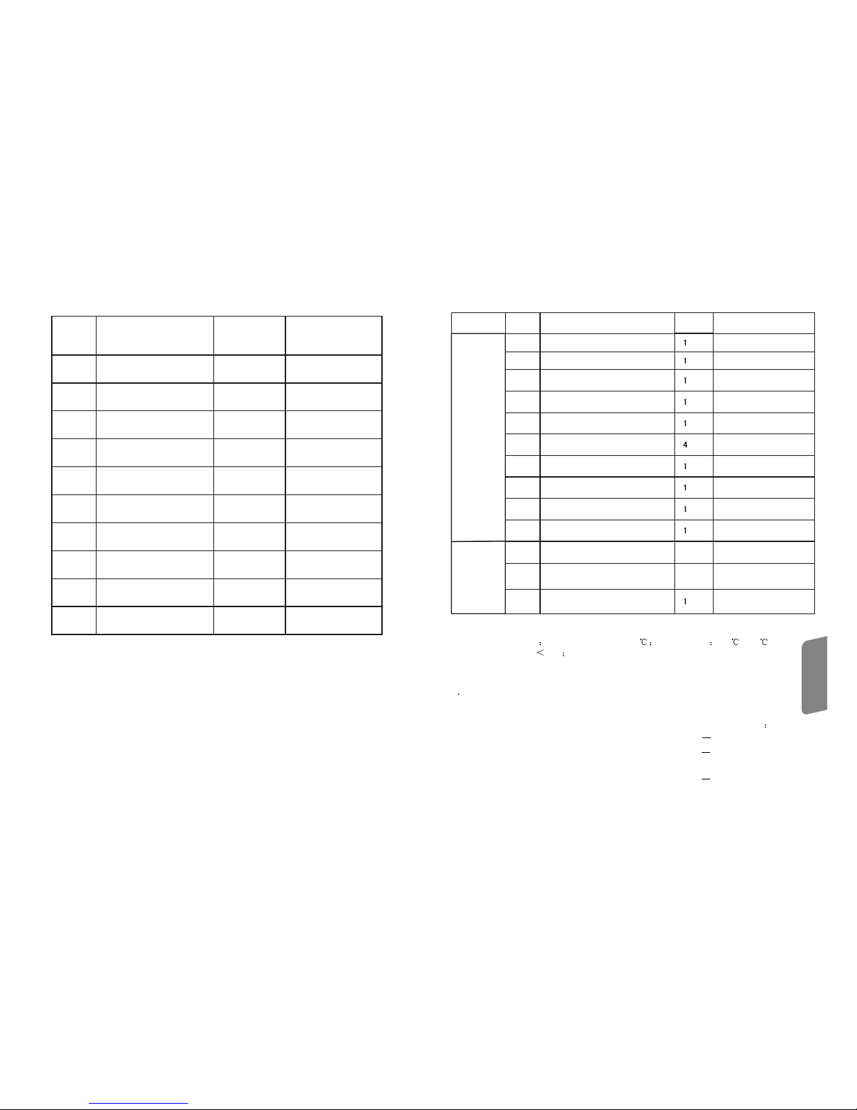
1.3 Specifications:
appendix two
No
Material
Leeb hardness
HLD
Intension 0 b (MPa)
1
C
350~522
374~780
2
C
500~710 737~1670
3
Cr
500~730 707~1829
4
CrV
500~750 704~1980
5
CrNi
500~750 763~2007
6
CrMo
500~738 721~1875
7
CrNiMo
540~738 844~1933
8
CrMnSi
500~750 755~1993
9
SSST
630~800 1180~2652
10
SST
500~710 703~1676
-24-
Name
Number
Remark
1
main unit
PCS
2
D type impact device
3
Standard leeb hardness block
PCS
4
A Nylon brush A
PCS
5
Support ring
PCS
6
AA alkaline battery
PCS
7
Manual
PCS
8
Alluminum box
PCS
9
software CD
PCS
10
USB cable
PCS
11
B Nylon brush B
For G type impact
device
12
Irregular type
and support ring
impact device
See appendix 3 and 4
Standard
packing
No
13
Leeb hardness testing
method for metals.
GB/717394-1998
PCS
PCS
Operation
Explanations
optional
accessory
HL=1000×VB/VA
Hl leed hardness
Vb rebound velocity
of the impact body
VA impact velocity
of the impact body
Table 1
Page 8
-06-
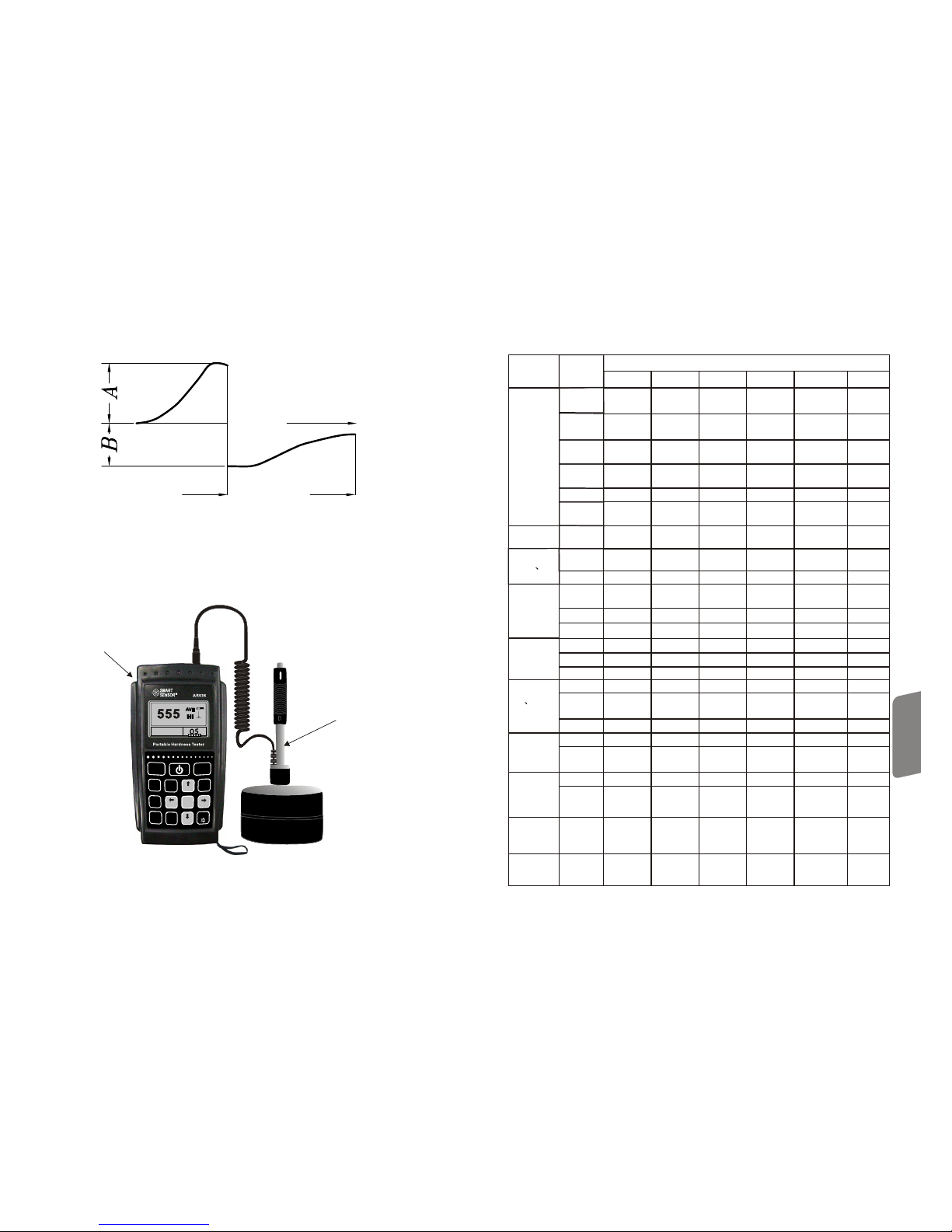
Voltage characteristic of output signal:
2.2
2.2.1 Hardness tester
Diagram of the instrument
HV
HRC
127~
364
HV
32~168
23.8~
85.5
40~173
13.5~
95.3
60~290
45~315
material
hardness
unit
impact device
D/DC
D+15
C G
E DL
steel and
cast steel
HRC
17.9~
68.5
19.3~
67.9
20.0~
69.5
22.4~
70.7
20.6~
68.2
HRB
59.6~
99.6
47.7~
99.9
37.0~
99.9
HRA
59.1~
85.8
61.7~
88.0
HB
127~
651
80~638 80~683
90~646
83~663
81~646
HV
83~976 80~937
80~996
84~1042
80~950
HS
32.2~
99.5
33.3~
99.3
31.8~
102.1
35.8~
102.6
30.6~
96.8
steel
HB
143~
650
CWT ST
HRC
20.4~
67.1
19.8~
68.2
20.7~
68.2
22.6~
70.2
HV
80~898
80~935
100~941
82~1009
Stainless
steel
HRB
46.5~
101.7
HB
85~655
HV
85~802
GC. IRON
HRC
HB
93~334 92~326
Nc
IRON
HB
131~
387
c. alum
HB
19~164
23~210
HRB
23.8~
84.6
22.7~
85.0
brass
HB
HRB
bronze
HB
copper
HB
Appendix
Appendix one
-23-
Main unit
Impact device
Impact phase
time
Rebound
Phase
Operation
Explanations
555555
V V
A A
EE
Hl Hl
Steel and cast steelSteel and cast steel
9
3
0
7
8
2
1
4
6
5
STORE
ENTER
9
3
DEL
0
DIR
7
AVE
8
HARDNESS
2
ESC
MAT’L
1
TIMES
4
MENU
6
5
Page 9
-07-
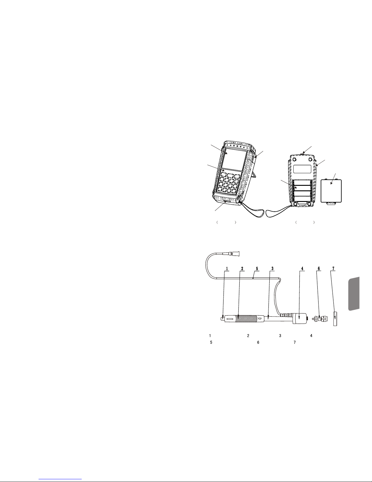
2.2.2 Main unit
2.2.3 D type impact device
release button load
supporting ring
tube guide tube coil holder
connecting cable impact head
-22-
8.1 Impact device
l After operation for 1000~2000 times, clean pipe and
with nylon brush. For cleaning the pipe, take out the body by
unscrewing the support ring, screw the nylon brush anticlockwise into the pipe until
the bottom then pull out, repeat this five times, then re-install the
and support ring.
impact device impact device tube
impact device tube
impact device tube
l After operation release the impact device tube.
l Forbid to use any lubricant for .impact device tube.
8.2 Instrument maintenance
l When checking with Rockwell hardness block and finding the error over 2HRC, it is
recommendable to replace the head or resulting from ball wearing.impact device
l In case that there is any malfunction of the instrument, the user shall not dismantle or
replace any component of the instrument, please fill in the guarantee card and return
the unit to our maitance department.
9. Instrument checkup
The checkup period shall not be more than one year, the users can decide its regular
checkup period at their convenience.
10. Storage and transport
l Keep the unit from the vibration, high magnetic field and erosive substance, humid
zone and dusty room in normal temperature.
away
l Keep the original package, the instrument can be transported on 3 level road.
µç³ØÃÅ
µç³ØÃÅ
LCD display
Keypad
Impact device socket
rear cabinet
battery door
Vibration-proof suit
USB socket
Battery
back sidefront side
µç³ØÃŵç³ØÃÅ
8. Maintenance and warracnty
Operation
Explanations
Page 10
-08-
2.2.4 Irregular impact device
3.Technical features
lSee table 2 for and reading repeatibilitytolorence
No
impact device
hardness of the block
tolorence of the
reading
reading
repeatibility
1
D
760 30HLD
530 40HLD
6 HLD
10 HLD
6 HLD
10 HLD
2
DC
760 30HLDC
530 40HLDC
6 HLDC
10 HLDC
6 HLD
10 HLD
3
DL
878 30HLDL
736 40HLDL
12 HLDL
12 HLDL
4
D+15
766 30HLD+15
544 40HLD+15
12 HLD+15
12 HLD+15
5
G
590 40HLG
500 40HLG
12 HLG
12 HLG
6
E
725 30HLE
508 40HLE
12 HLE
12 HLE
7
C
822 30HLC
590 40HLC
12 HLC
12 HLC
l Measuring range HLD 170~960 HLD
l Measuring direction: vertical down, side down, horizontal, side up and vertical down
-21-
6.11 Backlight
The white backlight facilitates operation in darkness, pressing button to turn on/off
the light in main menu interface.
6.12 Auto turn off
lThe function is to save the energy
lIf no further operation within 5 min the instrument will turn off automatically
lThe battery icon will be blank if there is low battery
6.13 Battery replacement
After long time operation, the battery icon becomes faded, the more black part the
more battery volume; after exhaustion of the battery, the batter icon shows ,this
means to replace the battery immediately.
Refer the following figure to install the battery:
6.14 Data transmission cable connection
Plug one end of the cable into the USB socket at the left of the host while the other
end into PC's USB socket.
7. Trouble shooting
Problem
Analysis
Action
Fail to turn on
Exhaustion of battery Replace battery
Wrong polarity connection
Connect the battery
in proper polarity
Blur reading
Low battery Replace battery
Replace the batteries as follow steps:
the unitlturn off
lTake off the vibration-proof glove on
the instrument, and open the battery
door and take out the old batteries.
lInsert the 4 fresh batteries with
correct polarity, then close the battery
door and take on the glove.
lTurn on the instrument to check if it
works properly.
lPay attention to the polarity of the
batteries, otherwise it may damage
the instrument.
battery door
Battery
µç³ØÃÅ
µç³ØÃÅ
--
++
--
++
--
++
--
++
positive
polarity
negative
polarity
l Material: steel & cast-steel, alloy tool steel, stainless steel, gray cast iron, nodular cast
iron, cast alluminum alloy, copper -zinc alloy,copper-tin alloy, pure copper, and forged
steel.
Operation
Explanations
Table 2
Page 11
l Hardness unit ( HL) HB HRB HRC HRA
HV HS
l Display 160*80 lattice LCD display
l storage up to 500 groups ( times:32~1)Data impact
l Operating voltage 6V
l Continuous operating time 50hrs without backlight.
4 Instrument operation:
4.1 Before operation
4.1.1 Requirements of the measured.
The surface of the measured must meet the requirements contained in table 3.
l The surface of the measured must be no more than 120 .
l The roughness can not be too high, otherwise errors may be occurred. The measured
surface must be polished and blare as smooth and flat as possible without oil smear.
l Weight of the measured: for the measured of more than 5kg, there is no need to
support; for that of 2~5kg or of thin walls construction, a support must be applied
while operating to avoid distortion, warpage and movement; for middle scale
workpiece, it must be placed in balance on a flat and concrete surface without any
vibration or moving.
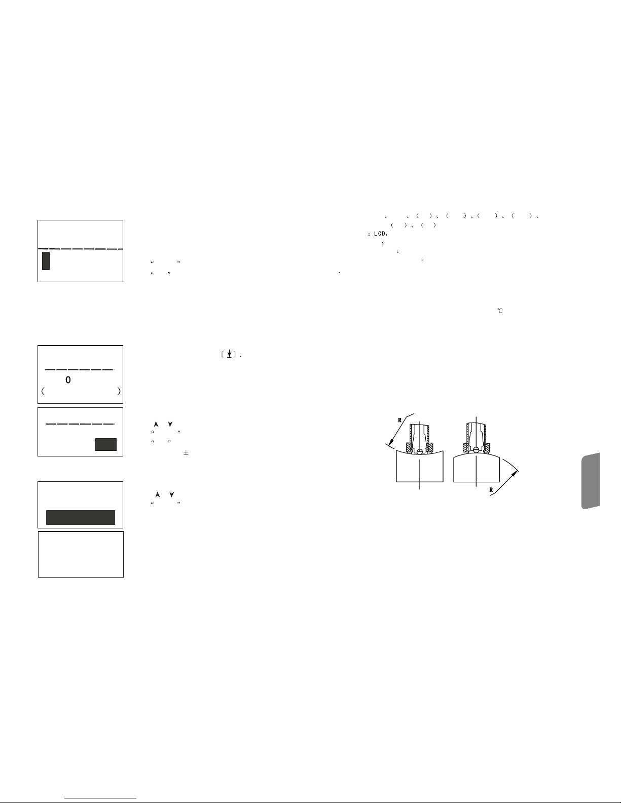
l Curve surface workpiece: the testing surface should be The small supporting
ring or irrregular type supporting ring shall be used for testing the workpiece which
has its curvature radius less than30mm(forD, DC, D+15, C, E and DL type
) and bigger than 50mm(G type ).
as flat.
impact
device impact device
-09-
-20-
6.8.2 Time / date setting
Current time/date displays on the LCD in format of
month/date/year hr/min.
Press number buttons to input the number, the cursor
will move from left to right repeatedly.
Press ENTER button to complete the setting.
Press ESC button to cancel the change.
6.9 System calibration
First operation, or use after a long time, the instrument and the must be
calibrated with the provided leeb hardness block. When several are
provided with , every only need one calibration, and no need
to re-calibrate when replacing .
Press menu to enter into system calibration submenu.
impact device
impact devices
main unit impact device
impact device
1 1 0/05/2005 11:02
time / date setting
After testing, averages display.
Press [ ] [ ]to input real value.
Press ENTER button to complete the calibration.
Press ESC button to exit the operation.
Calibraton range: 15hl.
system calibration
times
testing 5 times
Software Calibration
Average = 780
Real Value=
77
8800
6.10 software info
press menu to enter into main menu
This interface shows the info about the instrument and
the plug-in software
The software version no and plug-in software indentifier
is subject to change without further notification.
Storage Manager
system calibration system calibration
version No:AR936 B01
indentifier AR963BETA01
SN: 93600000
Setting the direction asimpact
With leeb hardness block, test 5 locatons in direction
of vertical downward.
System Configuration
l The workpiece must be of enough thickness, for the thickness please see
the appendix table 3.
minimum
l For the workpiece of rigid surface, the surface must comply with the requirements
prescribed in the appendix table 3.
l Coupling: for the light workpiece, it must be coupled with the solid supporting
body, the two coupling surface must be flat and smooth without too much coupling
agent applied. The testing direction must be vertical to the coupling surface. For
the workpiece of large area, long stem shape, or crook shape, even its weight and
thichness are enough, it is still possible to find the distortion and unbalance which
Press [ ] [ ] to move the cursor to software Info.
Press ENTER button to enter into software info.
Operation
Explanations
Page 12
-10-
4.1.2 Instrument system setting: see 6.8 for details.
4.1.3 Measuring condition setting: see 6.5 for details.
4.2 Measuring method:
l Calibrate the unit with the provided hardness block before operation,and its
and repeatibility shall be in line with the table 2.
tolorance
4.2.1 Starting
l Plug the head in the socket at the middle of the unit.impact
l Press [ ] button to turn on the unie.
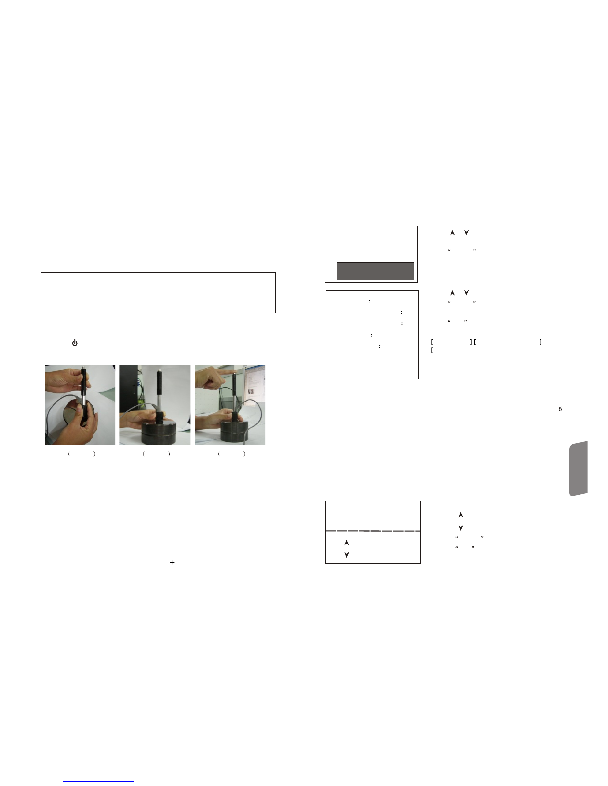
4.2.2 Loading( figure1)
l Push down the load to lock the body; for DC type
the load stem on the surface of the workpiece; for DC
insert the stem until stop for loading process.
tube impact impact device,
adsourb impact device,
4.2.3 Placement ( figure2)
Clamp the striking support ring against the the surface of the workpiece in the
selected direction vertically.
-19-
6.8 System configuration
Press menu to enter into main menu
Press [ ] [ ] to point the cursor to the System
configuration
Press ENTER button to enter into the menu.
Auto storage Eliminate the big error
Auto data transmission]
[Button sound][Alarming sound]can be turned
on/off by pressing the confirm button
l Auto storage: setting on will auto store the current group data after giving average
reading.
l Eliminate the big error: setting on will auto eliminate the big error bounding the 3
regulations after the advance ending of complete measurement by pressing average
button. If a data is eliminated, new data shall be supplemented to reach the times
preset.
l Auto data transmission: setting on will output the current data through USB
interface in text format after average reading is given.
l Button sound: setting on makes the buzzer beeps once at every button operation.
l Alarm sound: setting on makes the buzzer beeps once for a long time when the
measurement is beyond the allowance limits.
storage manager
system configurtionsystem configurtion
measuring
condition setting
auto storage off
eliminate the big error off
auto data transmission off
button sound on
alarming sound on
LCD brightness setting
time/date setting
6.8.1 LCD brightness setting
LCD brightness setting
press [ ] to increase the brightness
press [ ] to decrease the brightness
Press [ ] to increase the brightness
Press [ ] to decrease the brightness
Press ENTER button to complete the setting.
Press ESC button to cancel the change
figure 1 2figure 3figure
4.2.4 Measurement( figure3)
l Press the release button at the top of the device to measure while the
workpiece, device and operator must stand steadily and the force
should be in line with the axis of device.
impact
impact impact
impact
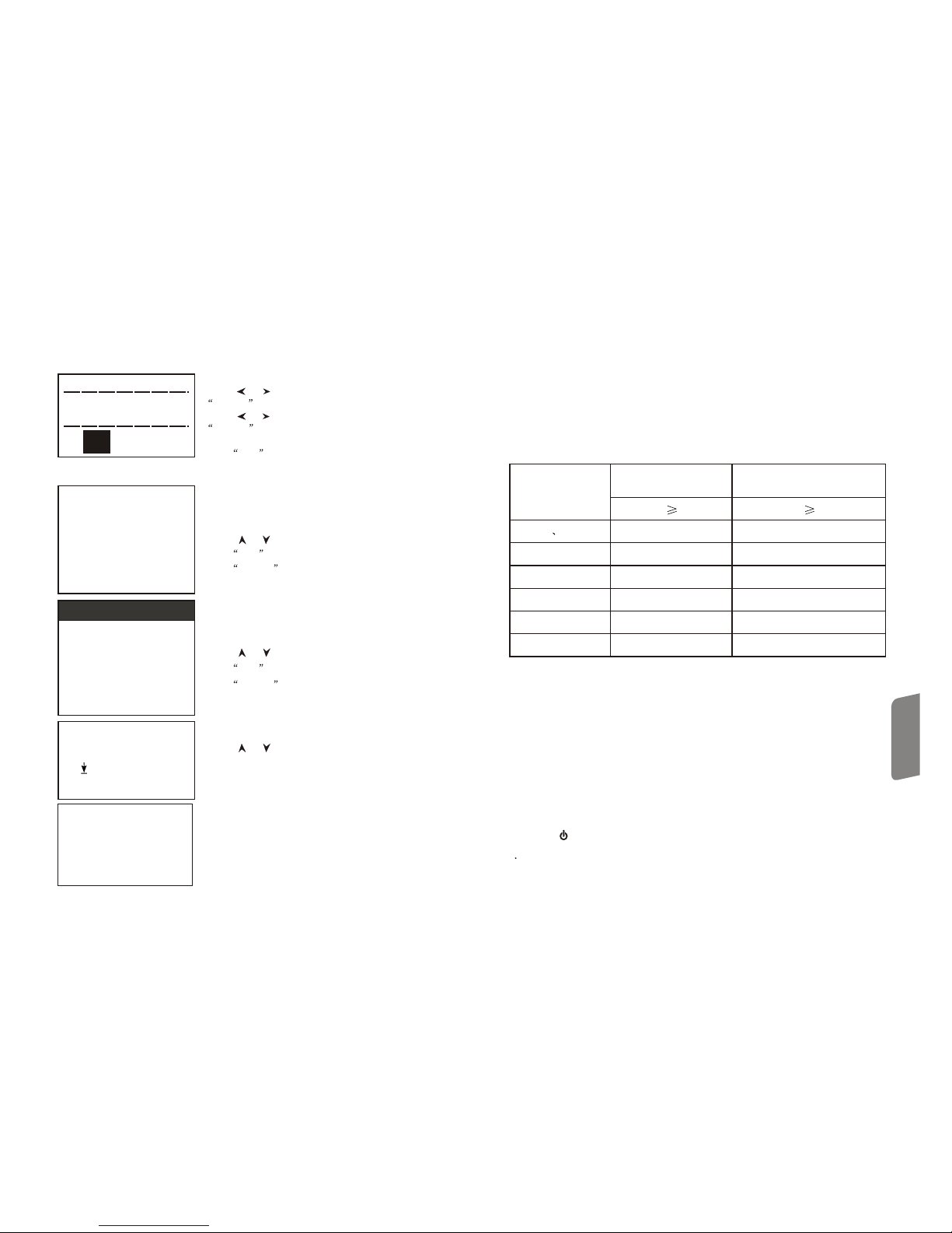
l Normally test 5 times for each location of the workpiece. The max difference
between these results should not be 15HLwithin
Note:
test the block in direction of vertical down for 5 times with the demarcated Leeb
tester, and take the arithmetic average as the hardness value of the block. If the
value is beyond the limit, use system calibration function to calibrate the unit.
lead to incorrect measuring, so reinforcing or supporting at the back of the workpiece
is necessary.
Press [ ] [ ] to move the cursor to the desired.
Press ENTER button to change or enter into the
change interface.
Press ESC button to exit
Operation
Explanations
Page 13
-11-
impact device
distance between
center of the 2 impress
the distance between the
center and edge of workpiece
DDC
3
5
DL
3
5
D+15
3
5
G
4
8
E
3
5
C
2 4
table 3
4.2.5 Read the value
l Take the average of readings from many valid testing locations as a Leeb hardness
data.
l Before the Leeb hardness signal HL is the hardness reading. After that is the type
of striking fitting type. For example, 780HLD means the tested hardness is 780 with
type D impact device.
l For conversion from Leeb reading, a corresponding hardness singal shall be
placed after the reading, for example, 420HVHLD means the Vicker reading is 420
with the type D impact device.
Note: The different impact device wiill have the different hl value reading, for
example:
4.2.6 Turn off
-18-
are you sure to delelte?
YesYes
No No
6.6.6 Confirm delete
6.7 Data review
No. 001 12/03 652HL
No. 002 12/03 587HL
No. 003 12/03 820HL
No. 004 12/03 693HL
No. 005 12/03 783HL
No. 006 12/03 782HL
No. 007 12/03 579HL
No. 008 12/03 687HL
No. 001 12/03 514HL
No. 002 12/03 785HL
No. 003 12/03 516HL
No. 004 12/03 789HL
No. 005 12/03 570HL
No. 006 12/03 852HL
No. 007 12/03 523HL
No. 008 12/03 796HL
Every LCD page displays up to 8 groups of
numbers, date and averages
Press [ ] [ ] to page up/down
Press ESC button to exit review
Press ENTER button to call cursor for further review.
A confirm interface appears when delete the data stored.
Press [ ] [ ] to move the cursor to Yes and press
ENTER button to delete the data.
Press [ ] [ ] move the cursor to No and press
ENTER button to cancel the delete. Regardless the
cursor position.
Press ESC button also lead to delete cancellation.
Press [ ] [ ] to select the group displayed.
Press ESC button to exit review
Press ENTER button to call cursor for further review
511 513 516
514 515
Max: 516 Min: 511
Number 001 12/03/02
average= 514HL
D 05 times
steel and cast steel
press “ “ button to turn off.
5 Special instruction:
l Replacement of battery must be performed after turn off the
unit, otherwise,the can not be identified and damage the unit.
impact device
impact device might
l Any distance between impresses and the distance between the center and the edge of
the workpiece shall be in line with the regulation of table 3.
l For specific material, a comparison test must be performed to get a conversion map if
you want to change the Leeb reading into other hardness value. This method is that
using properly calibrated Leeb tester and the desired tester to test on the same
workpiece at 3 locations nearby the target location and get 5 groups of the Leeb
readings. Then take the average of these readings and these from another tester to
make a conversion curve which at least must involve 3 pairs of sampling readings.
l The magnetism of the workpiece shall not be more than 15 gauss.
6.6.5 Delete all
Delete All will delete all the data stored in memory.
Press [ ] [ ] to page up/down and review the
averages, measuring conditions and single readings.
Operation
Explanations
Page 14
-12-
Leeb hardness tester
impact device
DD
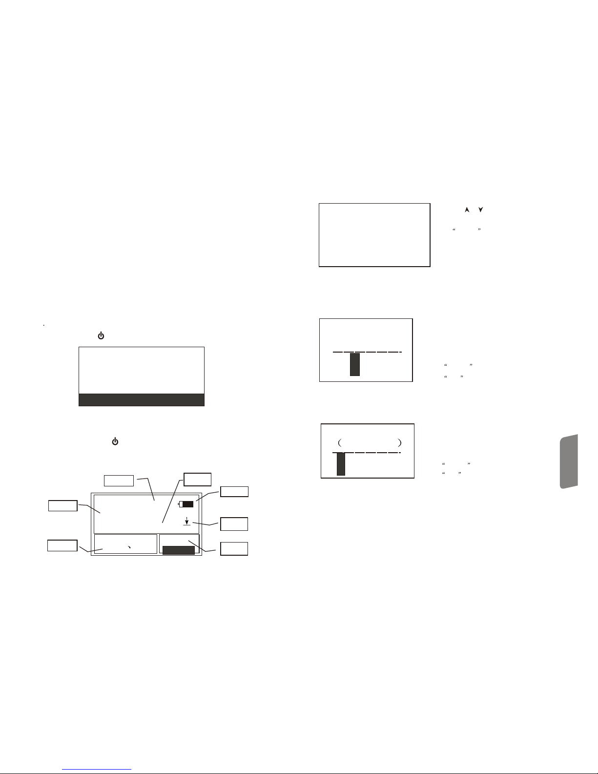
The instrument will check the and show on the LCD, check if the display
is right or not, then the unit enters into the main menu display.
impact device
6.3 Measurement
After turn on, the unit enters into the main menu as shown below:
-17-
6.6.1 Review from the first group/review from the last group
The former displays the data stored from the first goup
The later displays the data stored fromt the last group
6.6.2 Review from the selected group
lReview From the Selected Group will
display the start group interface
lPress number buttons to input the number
lPress ENTER button to confirm the choice
lPress ESC button to cancel the change
6.6.3 Data transmission
Data Transmission will transmit the data in text from USB interface.
Select the start group from
001 to 010
0 0 01
6.6.4 Delete the selected group
lDelete Selected Group will show the the
interface of the selected group to be deleted
lPress the number button to input the number
lPress ENTER button to confirm the choice
lPress ESC button to cancel the change
Note:
1. If the group number is beyond the existed, all the existed groups will be deleted
2. There is no differnce to input the first group number or final group number, ex,
delete 1 to 5 equals delete 5 to 1
3. After deletion, the number of the stored group will be re-numbered
4. In deleting, especially for single group delete, for re-number the existing stored data,
more 30 seconds is required, the instrument shall not be turned off to avoid messing
up the data.
selectable group from
001 to 017
0001
To
001
Press the [ ] [ ] to move the cursor to the
desired function
Press ENTER button to confirm the choice.
review from the first group
review form the last group
review from the selected group
data transmission
delete the selected group
delete all
AVE
784
HL
CWT ST
04
COUNTCOUNT
material
reading
average
hardness
unit
battery
impact
direction
impact
times
lNormally, the reading cannot be stored if the times is less than the preset value.
If you want to store the current reading, press the Average button to end the
measurement and store the value.
impact
lThis performance of advance end of measurement by pressing Average button disable
the functions of automatical storage and automatical transmission in the system munu.
lOnly D type and DC type enable the intension testing function, if other
are used the hardness/intension settings cannot be changed. In case that
if chage the setting as Intension with D/DC , then change the
with others, the Hardness/Intension setting will be changed into Hardness
automatically.
impact device
impact devices
impact devices impact
devices
lIf the setting is Intension, the hardness unit reset cannot be performed.
lNot all the material hardness can be converted into others, if the material is changed the
tester will be restored into Leeb hardness unit automatically. So material setting msut
be done before the hardness unit setting in process of condition setting.
6 Details of instrument operation
6.1 turn on: press[ ] to turn on as shown below:
6.2 In any case, press [ ] to turn off the unit.again
Operation
Explanations
Page 15
-13-
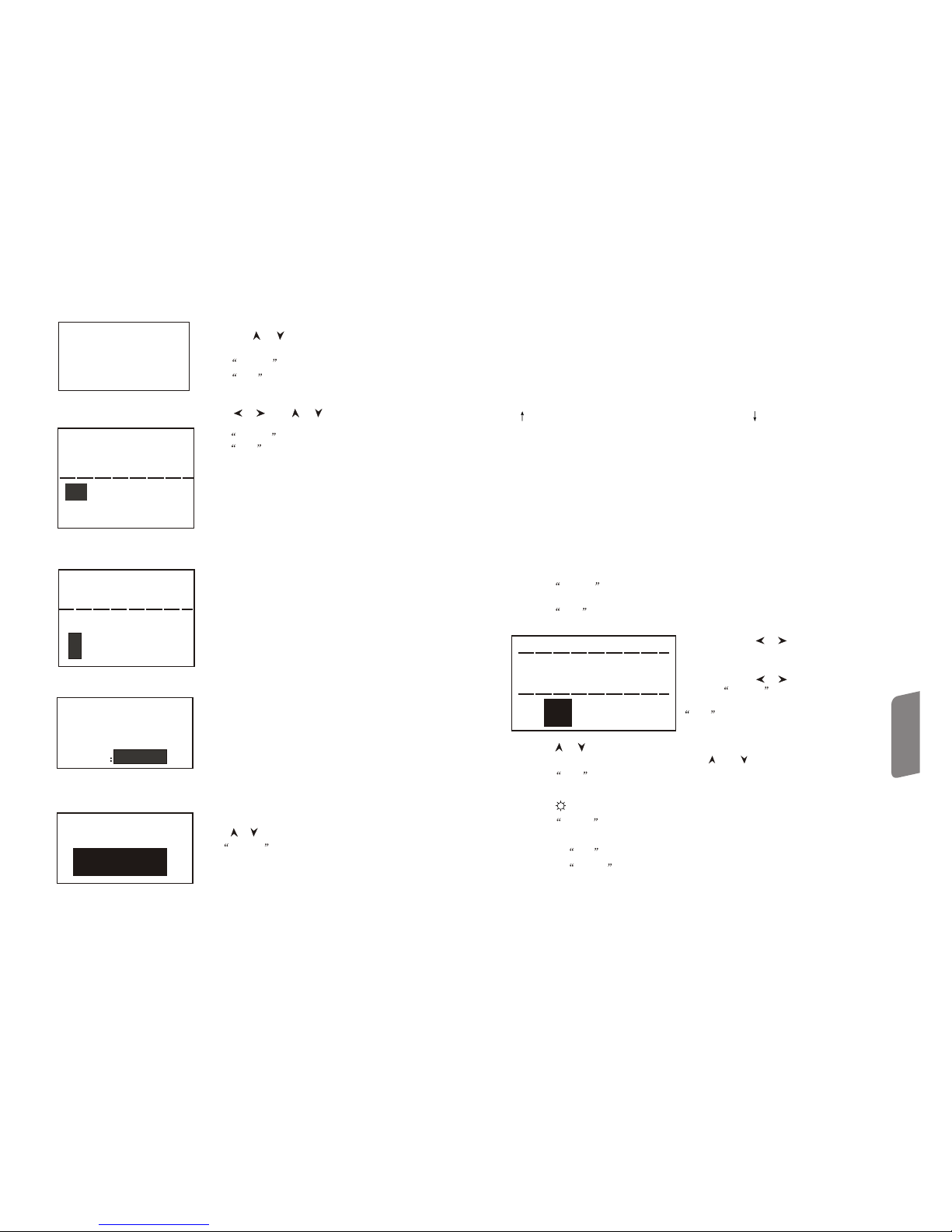
6.3.1 Main menu instruction
Battery: shows the residual battery volume.
direction: current direction
Average: when the preset times is reached, the average value shows.
Hardness unit: current unit
Reading: current single testing reading(without average alert), current average(with
average alert).
denotes value above convertable or measure range, denotes value below the
convertable or measure range.
Material: current material seting.
times: shows the times done with preset via Times button.
Times gives the info of the times and Single review gives the single readings
with is times of a single reading.
6.3.2 Measuring operation
At this interface, each testing will be displayed, and the times added with 1, if
the reading is beyond the , the buzzer gives a long beep; when preset times
is reached the buzzer 2 short beeps, then the average shows after 2 seconds with the
buzzer gives a short beep.
6.3.3 Button operation
l Press STORE button to store the current group reading, after the average is given.
The data can only be store once.
l Press DEL button to delete the last single reading, before the confirmation of the
following dialogue:
Impact
impact
Impact impact
impact
impact
tolerance
are you sure to delete?
yes yes
nono
l Press AVE button to end the measurement advancely before the preset
times and shows the average.
impact
l Press[ ]to turn on / off the backlight(this functions only in the main menu interface)
l Press MENU button to enter into main menu
l Quick set button
l Press the DIR button to set the direction.
l Press the TIMES button to change the times set, first press will display the
current the times set, each press add 1 until 32, then go back to the 1.
impact
l Press[ ] [ ] button to review the single readings, and press the Esc to restore the
average or last reading display, press the [ ] or [ ] can review the info in order.
-16-
6.5.4 Hardness unit setting
mild steel
high carbon steel
chrome steel
current material
hardness unit
HV HB HRC
HS HRB HRA
HL HL
6.5.5 limit settingTolerance
6.5.6 Hardness/intension setting
Press the [ ] [ ] to move the cursor to the desired
material
Press ENTER button to confirm the choice
Press ESC button to cancel the change
Press [ ] [ ] or [ ] [ ] to move the cursor to the
desired unit
Press ENTER button to confirm the choice
Press ESC button to cancel the change
Note:
1. Only the hardness unit available for convert with
suitable and material, for others this
cannot be displayed.
impact device
2. Select material before hardness unit setting
3. After material setting, the hardness unit will
be restored to HL automatically.
Press the Number button to input the number and the
cursor will move repeatedly from left to right.
Press confirm to confirm the choice
Press Esc to cancel the change
Note:
1. If the setting is beyond the range, the instrument will
alert you to reset.
2. If the low limit is bigger than the top limit, the
instrument will reverse the setting.
Press Confirm to select hardness/intension, the
cursor shifts between the hardness and intension
Note: 1. only D/DC are capable of
intension measurement, for the others this chocie is
Hardness only.
impact device
tolerance limit
low limit top limit
0 0 200 0890
material
hardness unit
tolerance limit
hardness/
intension
hardnesshardness
Press [ ][ ] to move the cursor to Storage manage
Press ENTER button to enter into storage manage menu.
If there is no data stored, “ NO DATA ” shows.
measuring
condition setting
storage manage storage manage
By pressing the [ ] [ ] button to move the
cursor to Yes and click the Confirm button to
confirm the delete of last single reading.
By pressing the [ ] [ ] button to No and
click the ENTER button to cancel the delete.
Regardless the cursor position, pressing the
ESC button can also cancel the delete
operation.
6.6 Storage manage
Press the Menu to enter into main menu
Operation
Explanations
Page 16
-14-
l Press MAT L button will change the material seting, each press will cycle the materials
preset in the instrument, and put the hardness as Leeb unit. So it is necessary to set
material before hardness set.
Note: The so called conversion means that based on the massive tests for Leeb
hardness and other hardness, a corresponding map is set up, and adopting this map the
tester calculates and converts the Leeb hardness into other units.
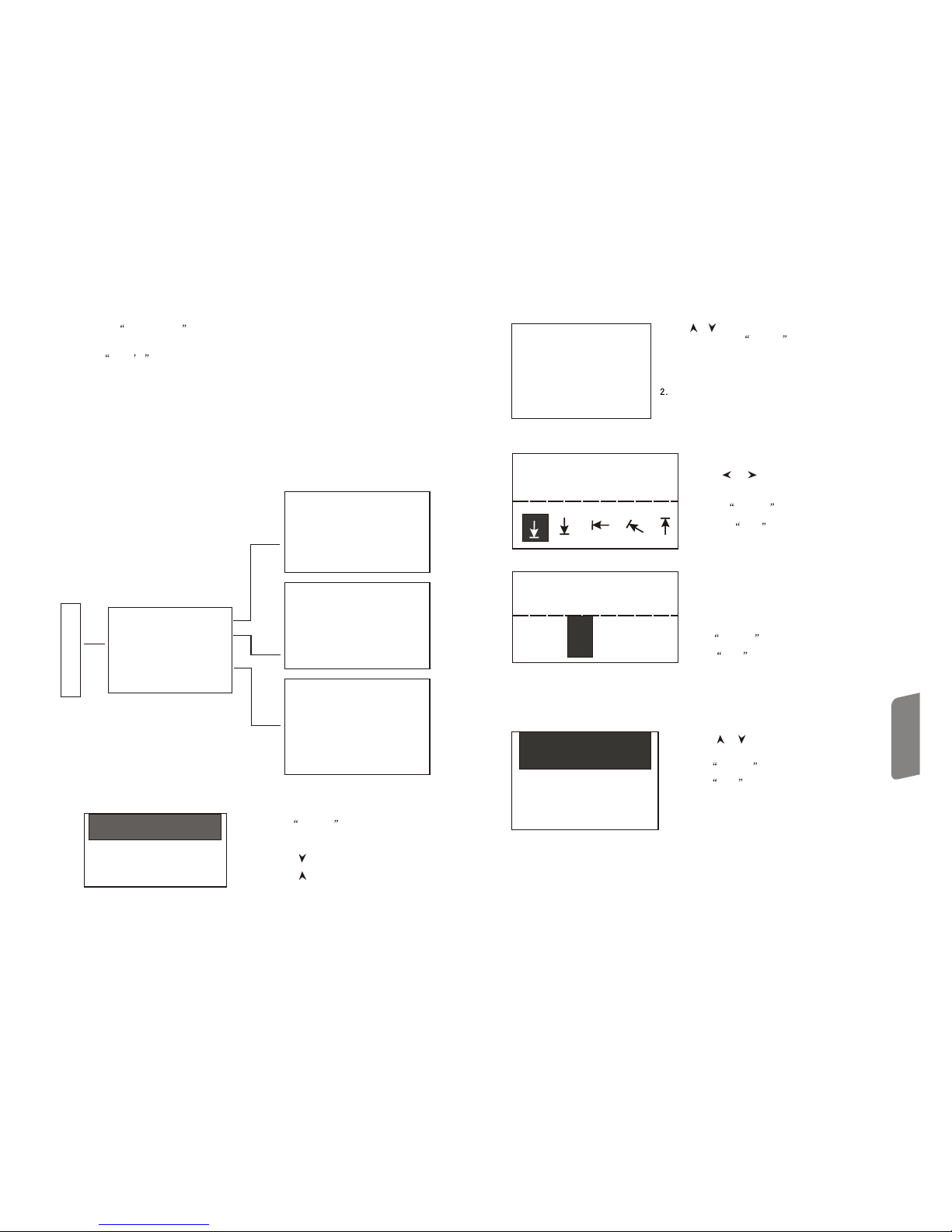
6.4 Menu tree
All the instrument parameters's configuration and added functions can be performed
with menu opertion, press the Menu button to enter into the main menu interface.
main menu interface
measuring condition setting
storage manager
system setting
system calibration
program info
impact
tolerance
direction
average times
material
hardness unit
hardness/intension:hardness
review from first group
review from the last group
review from the selected group
data transmission(preserved)
delete the selected group
delete all
automatic storage: off
eliminate the max error:off
auto data transmission:off
button sound: on
alarm sound: on
LCD brightness setting
time/date setting
6.5 measuring condition setting
Press Menu button to enter into main menu interface.
measuring condition settingmeasuring condition setting
storage manager
system configuration
l Press ENTER button to enter into
measuring condition setting menu.
l Press [ ] to review upward.
l Press [ ] to review downward.
Press [ ] [ ] button to move the cursor to the desired
condition and press ENTER button to confirm choice.
Note: 1. If the hardness/intension is set as intension,
hardness cannot be selected, the cursor jump over the
Hardness unit choice.
Only D/DC are available to
intension measuring, when using other ,
the cursor is not able to be moved to the Hardness/
Intension choice.
impact device
impact device
6.5.1 direction settingimpact
6.5.2 Average times setting
Available to select from 1 to 32.
Press the Number button to input the number
and the cursor will move repeatedly from left
to right.
Press ENTER button to complete the change.
Press ESC button to cancel the change.
Impact
tolerance
direction
average times
material
hardness unit
hardness / intension : hardness
impact direction
Press [ ] [ ] to move the cursor to the
desired direction setting.impact
Press the ENTER button to confirm the choice.
Press the ESC button to cancel the change.
average times
0 0
3
6.5.3 Material setting
If the Hardness/Intension is set as hardness, the following materials will show on LCD
steel & cast-steel, alloy tool steel, stainless steel, gray cast iron, nodular cast iron, cast
aluminium alloy, copper-zinc alloy, copper-tin alloy, pure copper, forged steel
Press the ENTER button to confirm the choice
Press the ESC button to cancel the change
Note: After material reset, the hardness unit will
automatically restore itself to HL
2. Before selecting hardness unit, set the material.
copper/zinc alloy copper/zinc alloy
copper-tin alloy
pure copper
forged steel
If the Hardness/Intension is set as Intension, the following selectable material shows:
Mild steel, high carbon steel, chrome steel, chrome/vanadium steel, chrome/nickle steel,
chrome/molybdenum steel, chrome/nickle/molybdenum steel, chromansil,super high
intension steel and stainless steel.
Press the [ ] [ ] to move the cursor to the
desired material.
-15-
l Press the HARDNESS button to set the hardness unit, each press change the unit of
the hardness, if the current set is intension it will go as Leeb hardness.
Operation
Explanations
 Loading...