

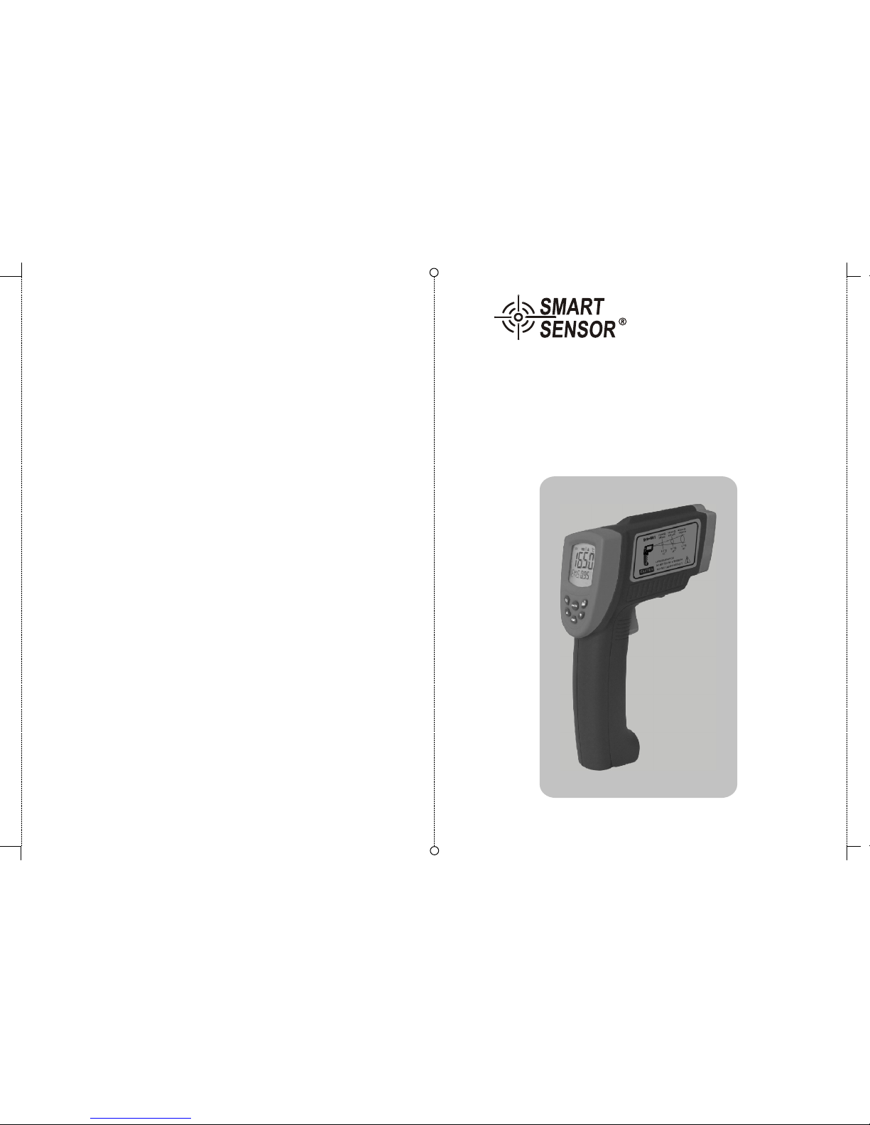
Non-contact infrared
thermometer Instruction manual
+
Model: AR882
-09-
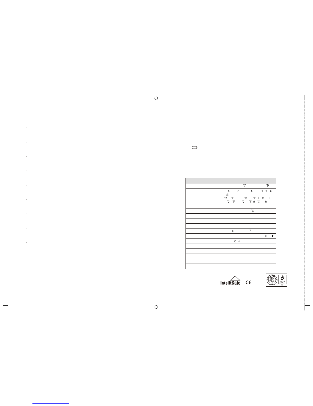
9.Specifications
1 Introduction----------------------------------------------(01)
2 How it works--------------------------------------------- (01)
3 Cautions--------------------------------------------------(02)
4 Operation Instruction---------------------------------- (02)
5 Quick Start Instruction---------------------------------(05)
6 ----------------------- (07)
7 Maintenance---------------------------------------------(08)
8 Note-------------------------------------------------------(09)
9 Specifications----------------------------------------- (09)
RS-232&DC IN PUT Interface
CONTENTS
8. Note:
8.1 Do not use solvent to clean lens.
8.2 Do not submerge the unit in water.
8.3 Do not use/place the unit in high temperature or moist
environment, that might inflect the units performance.
8.4 Do not change circuity of the unit, that possibly will
destruct the unit / endanger.
8.5 When icon display, means low battery power.
Please replace new battery to prevent inaccurate
measuring.
8.6 If unit not being use for long period, please unload the
battery.
Repeatability
1% of reading or 0.1
Response time
500 mSec, 95% response
Spectral response
8-14 um
Emissivity 0.10 to 1.00 adjustable (pre-set 0.95)
Ambient operating range
0 to 40 (32 to 104 )
Relative humidity
10-95% RH noncondensing, @ upto 30 (86 )
Storage temperature
-20 to 60 , 85%RH, without battery
Weight/Dimensions
480g ;220*134*60mm
Power
9v Alkaline or NiCd battery
Battery life (Alkaline)
Laser Models:12 hrs
Distance to Spot Size
50:1
Specifications
-18 to 1650 (0 to 3002 )
Temperature range
Accuracy
100 (212 ) to1650 (3002 ) 2
or 2%
0 (32 ) to 100 (212 ) 2 or 2%
-18 (0 ) to 0 (32 ) 3 or 3%
whichever is greater

-08-
1.Introduction
Compact, rugged and easy to use. Just aim and push
the button, read current surface temperature in less than
a second. Safely measure surface temperature of hot,
hazardous or hard-to-reach objects without contact.
2.How it works
Infrared thermometer measures the surface temper ature of an object. The unit's optics sense emitted, ref lected, and transmitted energy which is collect and fo cused onto a detector. The unit's electronics translate
the information into a temperature reading which is dis played on the unit.
For increased ease and accuracy the laser pointer
makes aiming even more precise.
Computer software disc 1pcs
RS232 /USB Input interface 1pcs
Main Parts 1pcs
English Manual 1pcs
Warranty card 1pcs
9V battery 1pcs
PP packing box 1pcs
----------------------
-------------------
----------------------------------
-----------------------------
-------------------------------
----------------------------------
------------------------------
-01-
RS232
9V
DC IN
(Figure5)
RS232 socket
Standard DC socketIN
6.1 For software installation and intructions, please
read the User Guide on CD.
6.2 Software function:
Check the data store off-line record curve graph.
6.3 DC : For saving battery consumption, please
use 9V 500mA adapter on long period measurement.
(Polarity show on socket label)
7M aintenance
7.1 Lens cleaning: Blow off lose particles using clean
compressed air. Gently brush remaining debris away
with a moist cotton cloth.
input
.
7.2 Case cleaning: Clean the case with a damp sponge
cloth and mild soap.

-07--02-
3.2Warning
-- Do not point laser directly at eye or indirectly off reflective
surfaces.
-- The unit cannot measure through transparent surfaces
such as glass or plastic. It will measure the surface
temperature of these materials instead.
-- Steam, dust, smoke, or other particles can prevent
accurate measurement by obstructing by the units optics.
4.1 When take measurement, point thermometer toward
the object to be measured and hold the yellow trigger.
The object under test should be larger than the spot size
calculated by the field of view diagram.
4.2 Distance & spot size: As the distance from the object
increase, the spot size of measuring area becomes larger.
4 Operation Instructions
3.Cautions
3.1Infrared thermometer should be protected for the following:
--EMF (electro-magnetic fields) from arc welders, induction heaters.
--Thermal shock (cause by large or abrupt ambient temperature
changes allow 30 minutes for unit to stabilize
before use).
--Do not leave the unit on or near objects of high temperature.
--Static electricity.
(8) LCD(see 5.1)
(9) Battery door clip
(10) Battery door: When replace battery, please press
battery door clip, pull down and forward the battery
door. Then install 9v battery correctly.
(11) Clesius / Fahrenheit switch: Please open battery
and push the slide switch for convertsion
6.R S-232&DC IN PUT interface
When connected AR882A+ with PC, DATA willd isplay
on LCD.D uring taking realt ime measurment, AUT
willb link on LCD.
h. PLY: Data reall function , press ,which can
recall the stored data .
i. CLR: Clear the Memory press the button of REC/CLR
two seconds can clear all stored data
j. Emissivity : Measuring Range 0.1-1.0 Adjustable
(6) Data Store press : REC/CLR
1.Storeage:
a.Press REC/CLR can store 1 unit data when in testing
model , Maximum data 4000units.
b.Press REC/CLR one seconds can Continuous record
the sampling data( press REC/CLR button on lock
status can finish store function ).
2.Checkup:
a.On PLY model , press ,can playback the
sampling data.
B.Press Set button , and can quick view it , and
connect the PC readout the data.
3. Clear:
On CLR model ,Press REC/CLR two seconds Can
clear record data
(7)Lock and Unlock function, Press the trigger on measuring
status ,press the set button will display the lock and
unlock icon .Lock Function---Means continuous
measuring,press mode button can unlock it( lock,
unlock)

-06- -03-
4.3 Field of view: Make sure the target is larger than the
unit's spot size. The smaller target the closer measure
distance. When accuracy is critical, make sure the target is
at least twice as large as the spot size.
4.4 Emissivity: Most organic materials and painted or
oxidized surfaces have an emissivity of 0.95 (pre-set in
the unit). Inaccurate readings will result from measuring
shiny or polished metal surfaces. To compensate for this,
adjust the units emissivity reading (see table below and
5.3 settings) or cover the surface to be measured with
masking tape or flat black paint. Measure the tape or
painted surface when the tape or painted reach the same
temperature as the material underneath.
4.5 Table of approximate emissivity
(Figure4)
1
8
(Figure3)
9
9V
DC IN
(2) Laser / back light button: when back light turn on ,any
operations will remain back light for 10 sec. LCD
indicate on/off status.
(3) (5) key functions: press 3 key, LCD subdisplay
MAX-MIN-AVG -HAL-LAL-SGN-PLY-CLR-EMS
display means normal
press 4 key to enter.
a. MAX: measuring maximum temperature
b. MIN: measuring minimum temperature
c. AVG: measuring average temperature
d
e. HAL: high temperature alarm--when selected
press 5 keys to set high temperature alarm
dconfirmed by pressing 4 key. When
trigger, LCD display HI icon with
f. LAL: low temperature alarm--when selected
press 5 keys to set low temperature alarm
blinks
-DIF
segment (only main measuring
mode)
. DIF: Basic on the reading before press 4 key,
compute the difference of current reading.
HAL,
trigger
an reading
over BiBi audio
sounds.
LAL,
trigger
and confirmed by pressing 4 key. When reading
over trigger, LCD display LOW icon with BiBi audio
sounds
g. SGN: data storage--when selected STO, lock &
DATA & 1---indicator will shown when press 4 key.
After temperature read out press 6 key to store,
then 2---memory unit will be shown.
REC/CLR
LASER
BACKLIT
MODE
SET
7
5
MODE
SET
REC/CLR
4
3
6
2
RS232
9V
DC IN
10-11
19mm@
300mm
18mm@
900mm
42mm@
1500mm
0.8”@ 0.7”@
36"
1.7”@
60"
D:S=50:1
12"

-05--04-
(Figure1)
A
B
C
D
E
F
G
H
I
J
K
5.2 Locating a hot/cold spot: To find a hot/cold spot, aim
the thermometer outside the area of interest, then
scan across with up and down motion until you locate
the hot/cold spot.
(Figure2)
9V
DC IN
5.Quick start instruction
5.1 LCD display: B measuring unit
A measuring reading D back light on icon
C laser on icon F scanning icon
E battery power icon G data hold icon
H mode/emissivity indicator I data storge / read icon
J low temperature alarm icon
K high temperature alarm icon
5.3 Diagram description
(1) Trigger: When turn on LCD display VERXX software
version for 1 sec. And turn to display reading with
SCAN icon. Release the trigger, display reading
with HOLD icon. Built in auto power off in 30sec.
RS232
9V
DC IN
0.30
0.95
0.95
0.70
0.50
0.90
0.85
0.95
0.95
0.95
0.94
0.90
0.93
0.85
0.98
0.70
0.50
0.98
0.94
0.93
0.95
0.95
0.95
0.90
0.98
0.90
0.80
0.94
0.93
0.94
Emissivity
Emissivity
Marterial
Marterial
Aluminum
Asbestos
Asphalt
Basalt
Brass
Brick
Carbon
Ceramic
Concrete
Copper
Dirt
Frozen food
Hot food
Glass(plate)
Ice
Iron
Lead
Limestone
Oil
Paint
Paper
Plastic
Rubber
Sand
Skin
Snow
Steel
Textiles
Water
Wood
 Loading...