

Page 1
PROGRAMMING INSTRUCTIONS
for
SRU Boards
www.smartrise.us | 1235 N. Union Bower Rd, Irving, TX 75061 | 916.457.5129
Page 2
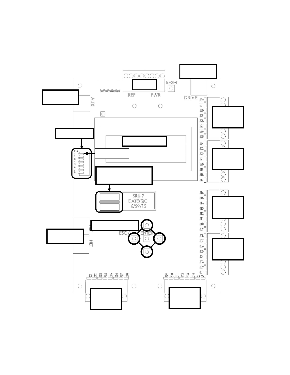
SRU Board Revision Layouts
POWER
DIP SWITCH
Inputs
525-532
Inputs
517-524
Inputs
501-508
Inputs
509-516
Outputs
601-608
Outputs
601-608
LCD SCREEN
Drive Port
AUX Port
NET Ports
JTAG PROGRAMMING
PORTS
LCD NAVIGATION
Dip Switch 1
Revision 5-7 Board
1
Page 3
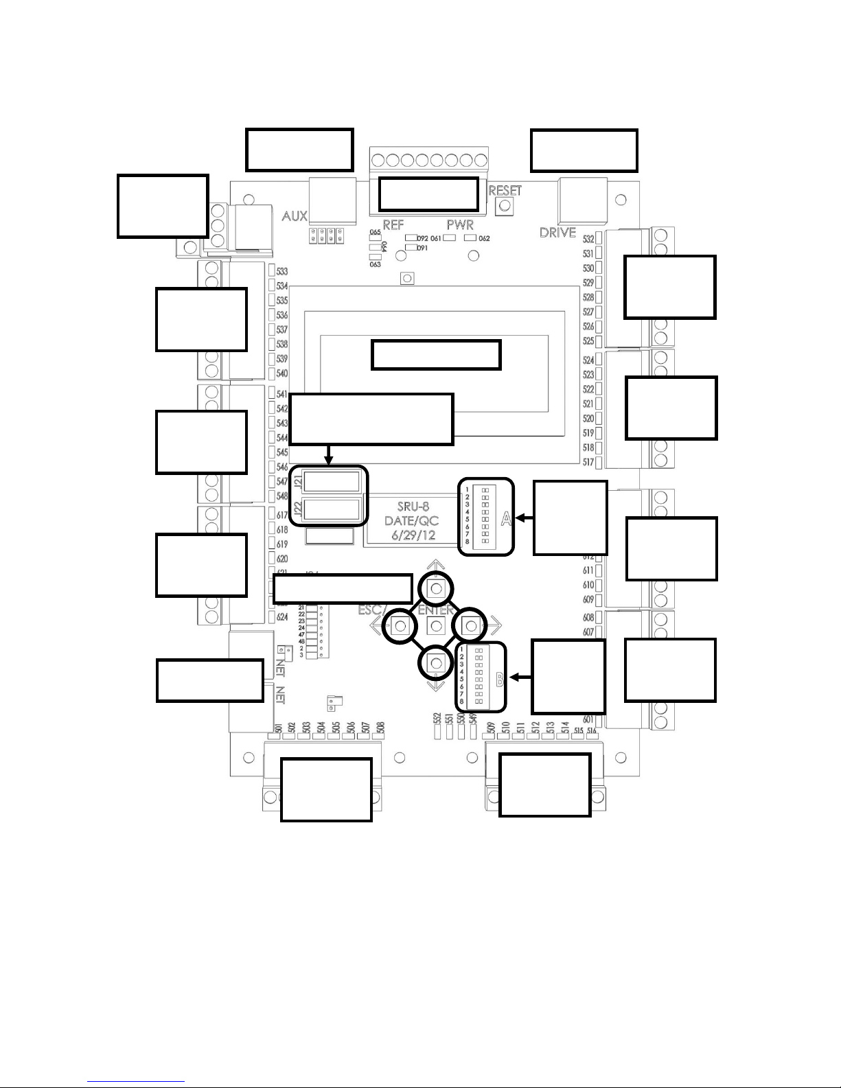
DIP
SWITCH
A
POWER
LCD SCREEN
JTAG PROGRAMMING
PORTS
Inputs
525-532
Drive Port
AUX Port
NET Ports
Inputs
517-524
Inputs
533-540
Inputs
501-508
Inputs
509-516
Inputs
549-552
Outputs
601-608
Outputs
601-608
DIP
SWITCH
B
Inputs
541-548
Outputs
617-624
LCD NAVIGATION
Revision 8 Board
2
Page 4
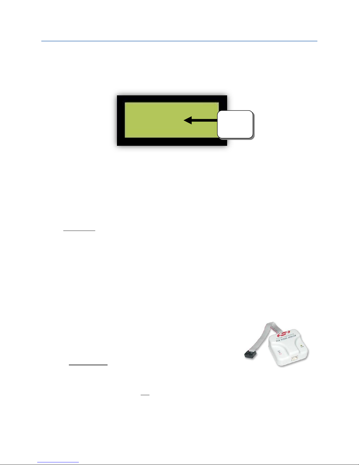
Access Code
Enter Access Code
Enter
“xFFFF”
Some software versions required an access code to be inputted when powering up a SRU board
for the first time. The access code is “xFFFF” and when prompted, press and hold the UP arrow
button on the SRU board until the display reads “xFFFF”, then press the enter key.
X0000
Tips to Preserve Your Settings During Board Replacement
The Machine Room (MR) board sends all settings and parameters to the Cartop (CT) and Car
Operating Panel (COP) boards. These settings are stored in each board. If the Machine Room SRU
goes out then the only way to save your jobs settings (Slowdowns, Floor Levels, Parameters, etc.)
is to replace it and reprogram it with either the COP board or the CT board. Follow these steps:
1. Replace the MR board with either the CT or COP board
2. Reprogram it as the MR board.
** DO NOT USE “DIP SWITCH 1” + “DEFAULT ALL” AFTER PROGRAMMING **
3. Install the new board as the CT or COP board and program it as such.
The previous settings in the reprogrammed MR board will then transfer to the new board and
the car should operate as before with all the original settings.
You can replace either the CT or COP board anytime as they will retrieve the settings from the
MR board when powered up.
USB Debug Adapter
To program an SRU board you will need:
Smartrise Programming Pod (USB Debug Adapter).
A fully charged laptop with either of the following operating
systems: Windows XP, Vista, 7, or 8.
The software for your specific job is provided by Smartrise in two ways: a Smartrise CD
included in the job binder OR by online download. Contact Smartrise if you don’t have
the software for your particular jobsite.
3
Page 5

Step 1 - Software Extraction to Laptop
Software provided by online download link
If an update was made to the job OR the CDs are missing, Smartrise can send an e-mail with a
link to a downloadable zip file for the software. For example:
http://smartrise.info/Software_packages/Smartrise_Job_(111112-001).zip
1. Click on the link and choose “Save As” to save the zip file to your laptop, preferably to
your desktop.
There are several ways to open a zip file. Your laptop should have the capability to extract
the file to a location of your choosing. If not you will need to download a free program
from the internet to process this file.
2. Navigate to the location you saved the file and double click on it to show the contents.
3. Some laptops won’t allow the Smartrise programmer to run directly from a zip file. To
resolve this you need to copy all the contents of the zip file to a folder on your laptop.
This will allow you to access all the folders necessary for installation (i.e. software,
Smartrise Programmer, etc.).
4. Now that the files are extracted to your laptop’s hard drive you can proceed with the
installation of the programmer (if not installed already) and the software.
4
Page 6

Step 2 - Installing the Smartrise Programmer
Special considerations need to be made when installing the software:
Do you have the Smartrise Programmer Application to install the software?
- If not, install the application by doing the following:
1. Open the (5) New Smartrise Programmer Folder in your software package
2. Open the 1 – Programmer Installer Folder
3. Install the Smartrise Programmer
4. Once the Smartrise Programmer is installed go back to the index of folders (shown below)
and open the:
(1) Controller Software folder with the JCF Software file inside shown below:
5
Page 7

5. Open the Software Folder, in this example the version is 2.20h, the version will vary on
how recent the job is.
6. Open the JCF file by double clicking on it. If it doesn’t open then the Smartrise
Programmer might not be correctly installed. Please see previous page for installation
instructions.
The Smartrise Programmer interface
Note: All the controller software is located on this interface except the group software.
6
Page 8

Software provided by CD
Revision 8 Board
Revision 5-7 Board
Ports J21 and J22
correspond to the JTAG
ports located on the
controller board.
Every Smartrise job is provided with a binder that consists of two CD’s containing software for
the specific job. Smartrise controllers are shipped initially with the software already installed on
the controller; these CD’s are provided as back-ups.
1. Insert the supplied CD into the CD ROM drive. Usually a menu similar to the one shown
below will appear. If no menu appears then open “My Computer” and click on the CD
ROM drive.
2. Click on the “Open folder to view files” option to explore the Smartrise CD folders. A list
of folders with the software will appear. The software is located in the “(1) – Controller
Software” folder.
It is imperative that you install the correct software onto the correct JTAG port.
To do this, first connect your Smartrise programmer to your laptop via USB, and then connect
the other end to the JTAG port on the controller.
7
Page 9

Step 3 - Installing the SRU Software
Warning: Your laptop needs to be fully charged for this process, plugging in your laptop to an
AC source while installing software could result in damage to the SRU Board. Also, do not
disconnect the programmer pod from the SRU board while the controller is being programmed.
Identify which controller you are installing, Machine room, Car-Top, COP.
Instructions for Programming a NEW Machine Room Controller
1. A controller cannot be programmed if unpowered, ensure that you have 24V supplied to
the controller.
2. Turn on Dip Switch 1 (Dip A). When you activate Dip Switch 1 you should see a “F77: CPU
Stop Switch” fault on the controller. Do not be alarmed – this is normal.
3. Plug the programming pod’s ribbon cable connector into the J21 port first. Select the J21
checkbox on the Smartrise programming application show below.
4. Next, click the “Begin Programming” button on the bottom of the programming interface
to begin programming your board.
5. Notice the progress report bar, when programming is finished, you will see a
a. "Progress: Done” when programming is finished.
b. NOTE: You will also want to verify that the POWER and RUN LED’s on the
programming pod itself are off before disconnecting from a controller.
6. Next move your programming pod from port J21 to J22, then click on the J22 check box
and begin programming.
7. When programming is finished:
CYCLE POWER – ** DO NOT PRESS THE RESET BUTTON **
8. IF REPROGRAMMING AN EXISTING SRU BOARD – Don’t perform the DEFAULT ALL
procedure as this will erase all existing settings. Skip to Step #10.
9. IF PROGRAMMING A NEWLY INSTALLED MR SRU BOARD ONLY – Go to MAIN MENU |
SET UP | DEFAULT ALL | select “Yes” and press the center button. The controller will begin
defaulting all the factory parameters to original programming (This could take several
minutes).
10. Once this is finished, cycle power again.
11. When the controller is fully powered and finished loading, turn off Dip Switch 1.
12. Verify that the controller is programmed correctly. This is done by going to the MAIN
MENU | ABOUT screen. If all the information is correct, the Machine Room Controller
has been successfully programmed.
8
Page 10

123 California
(C) 2014
Type of Controller
Software Version
Job Name
MR SRU
Version 2.35h
Instructions for Programming a CT/COP Controller
Programming these boards is very similar to programming a machine room controller. When
programming these boards it is not necessary to activate dip switch 1 and DEFAULT ALL.
A controller cannot be programmed if unpowered, ensure that there is 24V supplied to
the controller.
Plug in the programming pod into the J21 port first. Select the correct J21 checkbox on
the Smartrise programming application for the corresponding controller.
Next, click the “Begin Programming” button on the bottom of the programming interface
to begin programming the board.
Notice the progress report bar, when programming is finished, the display will show
"Progress: Done”. NOTE: Verify that the POWER and RUN LED’s on the programming pod
itself are off before disconnecting from the controller.
Next move the programming pod from port J21 to J22, click on the J22 check box and then
“Begin Programming”.
When programming is finished:
CYCLE POWER – ** DO NOT PRESS THE RESET BUTTON **
When the controller is fully powered and finished loading, verify if the controller is
programmed correctly by going to the MAIN MENU | ABOUT
If all the information is correct, the controller software has been successfully installed.
9
Page 11

Instructions for Programming a Group Controller for Non-Simplex jobs
The group controller software will be located in the Controller Software folder.
Locate the folder with the group software in it. The folder will clearly be labeled “Group
Software.” After locating the folder, proceed below.
1. A controller cannot be programmed if unpowered, ensure that you have 24V supplied to
the controller.
2. Activate Dip Switch #1 on the group controller. (The group controller will not fault like
the machine room controller)
3. Plug in the programming pod into the J21 port first. Select the J21 checkbox on the
Smartrise programming application show below.
4. Next, click the “Begin Programming” button on the bottom of the programming interface
to begin programming the board.
5. Notice the progress report bar, when programming is finished, the LCD display will show
"Progress: Done”. NOTE: Verify that the POWER and RUN LED’s on the programming pod
itself are off before disconnecting it from a controller.
6. Next move the programming pod from port J21 to J22, click on the J22 check box and the
“Begin Programming” button.
7. When programming is finished:
CYCLE POWER – ** DO NOT PRESS THE RESET BUTTON **
8. Next, go to the MAIN MENU | SET UP | DEFAULT ALL | select “Yes” and press the center
button. The controller will begin to default all the factory parameters (This could take
several minutes).
9. Once this is finished, cycle power again.
10. When the controller is fully powered and finished loading, turn off Dip Switch 1.
11. Verify that the controller is programmed correctly. This is done by going to the MAIN
MENU | ABOUT. If all the information is correct, the controller software has been
successfully installed.
10
 Loading...