

Smartrise F220 Equipment Installation Manual
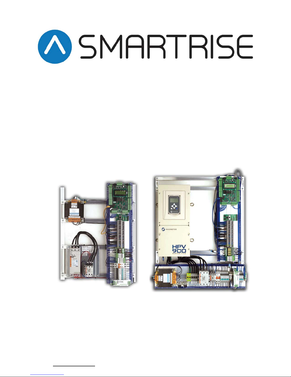
EQUIPMENTINSTALLATIONMANUAL
HydraulicControllers
ACTractionControllers
Thismanualcontainsinformationforsoftwareversion3
www.smartrise.us|2601FairOaksBlvd,Sacramento,CA95864|916.457.5129
Version3.16

Smartrise Engineering offers several options for customer training:
30 Minute phone introductory training for new customers
4 or 8 hour personal training classes at customer’s office or jobsite
4 hour regional training classes held throughout the U.S.A. & Canada
Online training videos to supplement regional training courses
To accommodate the busy work schedules of our customers all regional training
classes are 4–hours each and are held in one day from 8am to 5pm.
Training classes can also be performed at the customer’s site in place of the
universal 4 or 8-hour training.
Smartrise Training is recognized by the NAEC for CET credits for up to 8 hours.
For more information, contact the main office at (916) 457-5129 or send an email
to: Training@smartrise.us
1

WARRANTY
Products sold by Smartrise Engineering (Smartrise) are warranted to be free from defects in
workmanship and material for a period of fifteen (15) months from the date of shipment. Any
products defective in workmanship or material shall, at the discretion of Smartrise, be repaired
or replaced at no charge to the Buyer. Determination as to whether a product is defective and
eligible for an authorized return rests with Smartrise. The obligation of Smartrise shall be limited
solely to that of repairing or replacing of defective products returned to Smartrise by the Buyer.
It is the obligation of the Buyer to return defective products to Smartrise with all parts and
documentation. A return merchandise authorization (RMA) number must be obtained from
Smartrise prior to returning products.
Smartrise makes no warranty as to the fitness of its products for any application not specified in
writing by Smartrise. Use of Smartrise products in any unauthorized manner will void this
warranty and may cause damage to the product and/or injury.
This warranty is exclusive and in lieu of all other warranties, expressed or implied, including, but
not limited to, any warranty of merchantability or of fitness for a particular purpose and
therefore, the Buyer hereby waives any and all claims.
LIMITATIONS OF LIABILITY
In no event shall Smartrise Engineering be liable for loss of profit, indirect, consequential, or
incidental damages whether arising out of warranty, breach of contract or tort. Failure to
understand the elevator control system could result in damage to the system and possibly even
danger to the passengers. Only properly trained and qualified personnel should attempt to work
on the system.
CODE COMPLIANCE
Smartrise controllers are certified by ASME A17/CSA B44 and the State of California. Depending
on the jurisdiction where the controller is operating, it will be configured per the specific local
code requirements as specified by the buyer.
2

PERSONAL SAFETY: PERSONAL INJURY
AND/OR DEATH MAY OCCUR
Smartrise Engineering controllers should only be installed by qualified, licensed, trained elevator
personnel familiar with the operation of microprocessor-based elevator controls. All safety
devices, known as electronic protective devices (limits, governors, hoistway locks, car gate, etc.)
shall be tested to be fully functional prior to attempting to run the elevator. Never operate the
system with any safety device rendered inoperative in any way. The User is responsible for
compliance with the current National Electrical Code with respect to the overall installation of
the equipment, and proper sizing of electrical conductors connected to the controls. The User is
responsible for understanding and applying all current Local, State, Provincial, and Federal Codes
which govern practices such as controller placement, applicability, wiring protection,
disconnections, over current protection, and grounding procedures. To prevent the risk of
personal shock, all equipment should be securely grounded to earth ground as outlined in the
National Electrical Code. Failure to obtain an actual earth ground source may result in electrical
shock to personnel.
EQUIPMENT SAFETY
All equipment chassis should be securely grounded to earth ground as outlined in the National
Electrical Code. Improper grounding is the most common cause of electrical component failures
and electrically noise-induced problems. All component replacement must be done with the
main line power off. Unauthorized modifications to circuits or components should not be
attempted without Smartrise Engineering authorization to ensure all safety features are
maintained. Care should be taken when using test leads and jumpers to avoid applying high
voltage or ground to low voltage microprocessor circuits.
3

CONTROLLER GROUNDING REQUIREMENTS
NOTE – For the controller to function properly it is very important to
provide proper building ground connections to the controller.
Examples of a proper building-to-controller ground connection is
to attach the ground cable to:
The street side of the incoming water main.
To a grounding rod that has been driven into the pit flooring.
The controller has a common ground bus terminal connection.
All grounds need to land at this common point including building,
motor, transformer, and filter grounds. This prevents ground loops,
and will limit the impedance between the grounds and noise will
be channeled back to building ground.
Providing a proper ground is mandatory and will improve the
performance of the controller.
4

TABLE OF CONTENTS
CONTROLLER GROUNDING REQUIREMENTS ................................................................................................ 4
GENERAL INFORMATION .............................................................................................................................. 9
Bypass Term Limits ................................................................................................................................. 19
HYDRO INSTALLATION ................................................................................................................................ 21
Main Power Setup ................................................................................................................................... 22
Motor Wiring – 3/9 Lead Motor Wiring .................................................................................................. 23
Motor Wiring – 6/12 Lead Motor Wiring ................................................................................................ 24
Valve Wiring ............................................................................................................................................ 25
Soft Start setup – Sprecher + Schuh ....................................................................................................... 26
Soft Start setup – Siemens ...................................................................................................................... 30
AC TRACTION INSTALLATION ...................................................................................................................... 36
Main Power Setup ................................................................................................................................... 37
Motor & Brake Wiring ............................................................................................................................. 38
Encoder Wiring (Instructions per Manufacturer Drive Type) ..................................................................... 39
MAGNETEK HPV900-S2 DRIVE ................................................................................................................ 46
INDUCTION MOTOR SETUP ................................................................................................................. 46
PERMANENT MAGNET SETUP ............................................................................................................. 51
MAGNETEK L1000A DRIVE ...................................................................................................................... 58
INDUCTION MOTOR SETUP ................................................................................................................. 58
PERMANENT MAGNET SETUP ............................................................................................................. 64
KEB DRIVE................................................................................................................................................ 71
INDUCTION MOTOR SETUP ................................................................................................................. 71
PM MOTOR SETUP .............................................................................................................................. 80
Brake Board Adjusting & Replacing Procedure ........................................................................................... 90
Brake Board Replacement ...................................................................................................................... 91
Brake Board Adjustment ......................................................................................................................... 92
STEEL TAPE LANDING SYSTEM .................................................................................................................... 96
IP8300 SELECTOR, TAPE AND MAGNETS ................................................................................................ 97
DOOR ZONE MAGNET INSTALLATION – TAPE ....................................................................................... 100
TRACTION DZ1/DZ2 MAGNET PLACEMENT – ALL LANDINGS ........................................................... 101
HYDRO DZ1/DZ2 MAGNET PLACEMENT – TOP TERMINAL LANDING ............................................... 102
HYDRO DZ1/DZ2 MAGNET PLACEMENT – INTERMEDIATE LANDINGS ............................................. 103
5

HYDRO DZ1/DZ2 MAGNET PLACEMENT – BOTTOM TERMINAL LANDING ....................................... 104
UT1/DT1 MAGNET DESCRIPTION – TAPE .............................................................................................. 105
UT1/DT1 MAGNET ALIGNMENT – TAPE ............................................................................................... 106
UET/DET MAGNET PLACEMENT – TAPE ................................................................................................ 107
HOISTWAY SWITCH POSITIONING TABLE – NTS ............................................................................... 108
TAPELESS LANDING SYSTEM ..................................................................................................................... 109
GOVERNOR ENCODER LANDING SYSTEM INSTALLATION ..................................................................... 113
UET/DET MAGNET PLACEMENT – RAIL ................................................................................................. 121
NTS MAGNET PLACEMENT – RAIL ......................................................................................................... 122
SLIDE DISTANCE DETERMINATION PROCEDURE FOR ETS MAGNET PLACEMENT .................................... 123
MANUAL ETS and FINAL LIMIT SWITCHES ................................................................................................ 130
FINAL SWITCH PLACEMENT - TAPE ....................................................................................................... 131
FINAL SWITCH PLACEMENT – RAIL ....................................................................................................... 132
SMOKE SENSORS, SHUNT, & LOAD WEIGHING ........................................................................................ 133
Smoke Sensor Setup ............................................................................................................................. 134
SMOKE SENSOR SETUP ILLUSTRATION – LOWER LEVEL MACHINE ROOM ....................................... 138
Shunt Operation .................................................................................................................................... 139
Load Weighing ...................................................................................................................................... 140
EMERGENCY POWER & SAFETY STRING ................................................................................................... 141
Emergency Power ................................................................................................................................. 142
SAFETY STRING DESCRIPTION ............................................................................................................... 143
SAFETY STRING TROUBLESHOOTING ................................................................................................ 143
DOOR OPERATOR GENERAL ...................................................................................................................... 144
INSTALLATION ........................................................................................................................................... 144
MOVFR DOOR OPERATOR ..................................................................................................................... 145
MOVFR DOOR OPERATOR – G.A.L. CERTIFIED PHE ........................................................................... 146
IPC DOOR OPERATOR CONTROL MODEL D3000 ................................................................................... 147
Adjusting Door Dwell Times .................................................................................................................. 152
Battery Lowering Device ........................................................................................................................... 153
Reynolds & Reynolds Battery Lowering Device – “BLD” ....................................................................... 154
BLD / MOVFR Door Operator Voltage Issues ........................................................................................ 156
Learning the Hoistway .............................................................................................................................. 157
Adjusting Car Speeds ................................................................................................................................ 161
Car Speed Profiles Overview ................................................................................................................. 162
Adjusting Floor Levels ............................................................................................................................... 166
6

Adjustment Too High/Too Low method ............................................................................................... 167
Adjusting up/down Stop Points method............................................................................................... 169
Testing Procedures for Hydro Controllers ................................................................................................ 172
Emergency Power Testing ..................................................................................................................... 173
Normal Limit Testing Setup ................................................................................................................... 174
Normal / NTS Stopping test .................................................................................................................. 175
ETS Slowdown Test ............................................................................................................................... 176
Normal/Directional limits Test .............................................................................................................. 177
Re-leveling with In-Car Stop switch (Hydraulic System): ...................................................................... 177
Redundancy test ................................................................................................................................... 178
Battery Lowering Test ........................................................................................................................... 178
Buffer Test ............................................................................................................................................. 179
Stop Ring Test – Low Speed .................................................................................................................. 180
Low Oil / Low Pressure Test .................................................................................................................. 180
Leveling Speed Test (v2.35e or newer only) ......................................................................................... 181
Leveling Zone Test................................................................................................................................. 181
Pressure Test (Hydraulic System): ........................................................................................................ 182
Hydro Rupture setup............................................................................................................................. 182
Testing Procedures for Traction Controllers ............................................................................................. 183
Normal Limit Testing Setup ................................................................................................................... 184
NTS SWITCH DRIVE SETUP .................................................................................................................... 185
NTS SWITCH POSITION SETUP ............................................................................................................ 189
NTS SWITCH TESTING PROCEDURE .................................................................................................... 191
EMERGENCY TERMINAL STOPPING DEVICE (ETS) ............................................................................. 191
NORMAL/DIRECTIONAL LIMITS............................................................................................................. 193
REDUNDANCY TEST ............................................................................................................................... 194
MANUAL BRAKE RELEASE TEST ............................................................................................................. 194
BATTERY LOWERING TEST .................................................................................................................... 194
BUFFER TEST ........................................................................................................................................ 195
PRESSURE TEST (HYDRAULIC SYSTEM): ............................................................................................. 196
RE-LEVELING WITH IN-CAR STOP SWITCH (HYDRAULIC SYSTEM): ....................................................... 196
STOP RING TEST – LOW SPEED ............................................................................................................. 197
OVERSPEED AND GOVERNOR TEST – MAGNETEK DRIVE ..................................................................... 198
OVERSPEED AND GOVERNOR TEST – L1000A ....................................................................................... 199
EARTHQUAKE COUNTERWEIGHT TEST ................................................................................................. 201
7

LEVELING ZONE TEST ............................................................................................................................ 201
UNINTENDED MOVEMENT ................................................................................................................... 202
RACK AND PINION DROP TEST .............................................................................................................. 203
LOSS OF TRACTION TEST (2010 code compliance only) ....................................................................... 204
OTHER ADJUSTMENTS .............................................................................................................................. 205
ACCESS TOP/BOTTOM LIMITS: .............................................................................................................. 205
POSITION INDICATOR VIA CE: ............................................................................................................... 205
RESYNCHING - HYDROS ......................................................................................................................... 205
SIMPLEX PARKING SETUP ...................................................................................................................... 205
HYDRO RUPTURE SETUP ....................................................................................................................... 205
SMARTRISE MENU DEFINITIONS ............................................................................................................... 206
FAULTS & ALARMS .................................................................................................................................... 214
Common Fault Clearing Procedures ..................................................................................................... 217
ALARM DESCRIPTION INDEX ..................................................................................................................... 249
SRU INPUT / OUTPUT PROGRAMMING TUTORIAL ................................................................................... 253
APPENDIX A – SMARTRISE BOARDS .......................................................................................................... 256
APPENDIX B – MAKING CAT5 CABLES ....................................................................................................... 258
APPENDIX C – REPLACING RELAYS ............................................................................................................ 259
ADDENDUM I – REPLACING AND PROGRAMMING A DEFECTIVE SRU BOARD ......................................... 262
ADDENDUM II – ENCODER WIRING TABLES ............................................................................................. 269
ADDENDUM III – TRACTION BRAKE PICK OPERATION .............................................................................. 270
ADDENDUM IV – PARAMETER ADJUSTMENTS ......................................................................................... 271
ADDENDUM V – SECURITY ........................................................................................................................ 274
ADDENDUM VI – SCREEN LOCKOUT FEATURE .......................................................................................... 276
ADDENDUM VII – PI CONVERSION TABLE ................................................................................................. 277
8

GENERAL INFORMATION
THE JOB BINDER
The job binder is a 2.5” white binder that contains specific information about the job
you are installing. The cover contains the job name and job number that is required
for technical support with Smartrise Engineering. This binder should be kept at the
jobsite at all times for future reference and troubleshooting.
COMPONENTS
The following components are included in each job binder.
1. Software
a. The binder contains a 256meg USB flash drive that contains all the software,
drawings and programs needed for each specific job.
2. Drawings or Prints
a. There are anywhere from 13 to 17 sheets of drawings that pertain to that
specific controller. These prints include an index indicating the job specifics,
tables that show correct dip switch settings, jumper settings for individual
boards, and factory and field wiring diagrams and generic wiring references.
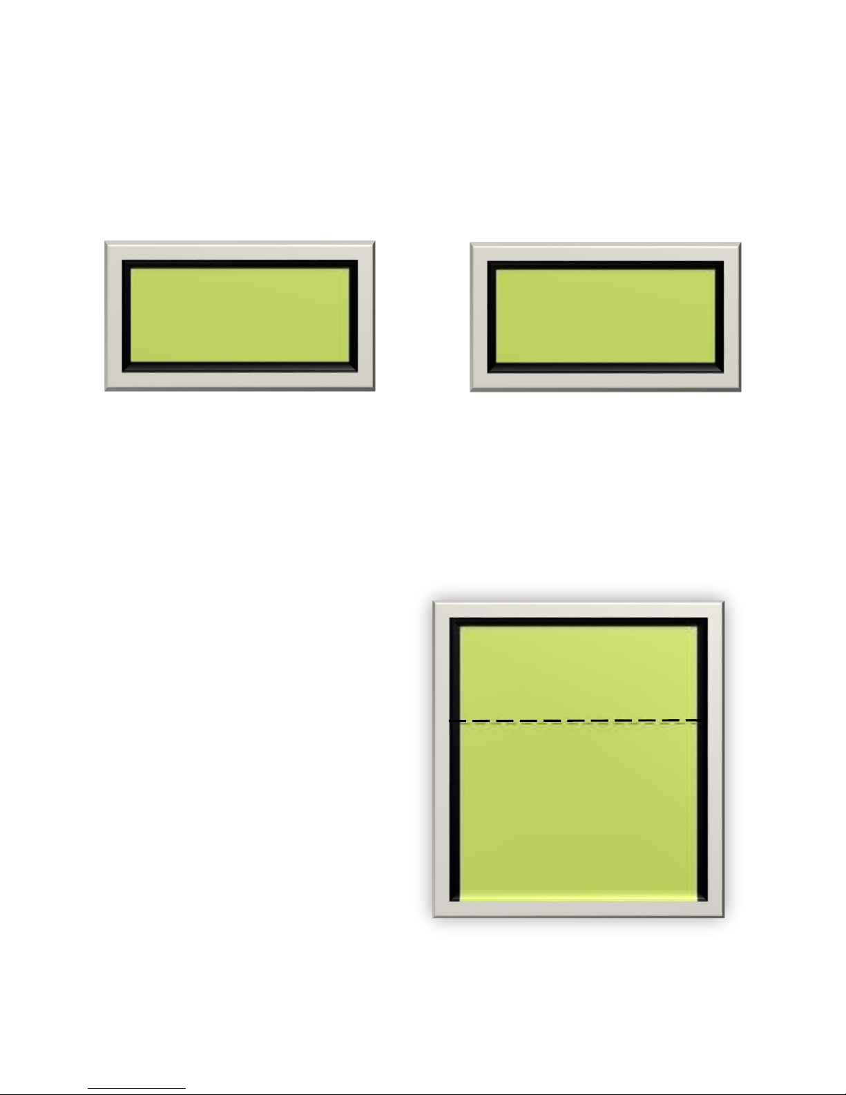
i. The solid lines on the prints show factory installed wiring.
ii. The dashed lines show installer wiring.
b. If the voltages or wiring for your job does not match the Job Specification table
on the ‘Sheet 01: Getting Started’ page of the drawings, contact Smartrise
Engineering for clarification before powering up.
3. Manual
a. The Equipment Installation Manual contains useful information for installation,
testing, adjusting, troubleshooting, menu navigation and much more.
For the most recent version of our installation manual go to
www.smartrise.us, click on Support and download a pdf copy of our latest
release.
4. IO Sheets
a. All binders include an IO sheet that shows each board’s input & output
programming. This is very useful when locating a specific IO for installation
and/or troubleshooting and for recording changes in the SRU IOs.
5. Drive, Door Operator, and other operating manuals (optional)
9

Common Installation Issues & Procedures
CARTOP COMMUNICATION ISSUES
Make sure to connect the shield of the CN+/CN- shielded pair to reference (REF) on
both ends. This communication cable part of the traveler located between the
machine room and car top board. Make sure the CN+ & CN- wires are connected to
the same terminals in the machine room as well as the cartop DIN rails.
Special Note on 2-Board Systems – Make sure the software on the COP SRU
says “Prewire CT” and NOT “Prewire COP”. Prewire COP software WILL NOT
communicate with the machine room SRU board.
HALL BOARD COMMUNICATION TESTING
To test communication on any hall board turn on Dip Switch 8. The two green LEDs
on the hall board blink indicating it is transmitting and receiving communication
from the machine room. This is a test dip switch only. Do this one floor at a time
when installing the hall boards; it will confirm that the wiring and board are good.
Always do this before moving onto the next floor.
JUMPING OUT UNUSED INPUTS
If the drawings show a normally closed contact for an Input your system does not
require, apply a jumper from 24vdc to the specified Input terminal. All Smartrise
boards Receive 24vdc inputs ONLY and provide 24vdc reference via programmed
outputs.
Entering Car Calls
You can enter a car call from the Machine Room or Cartop SRU by going to MAIN
MENU | DEBUG | ENTER CAR CALLS and using the Up/Down arrow keys to select
a floor to go to. Press the Enter button to latch that floor.
NOTE: There will be a noticeable delay between the time a call is latched and
the time the car actually initiates the call. This is normal because the call is
initiated through the software and not the physical car call button.
*** Note: Before getting started, take a few minutes learning to
navigate the LCD reader of the Smartrise board. The board and the
menu options are the same for all locations (MR, CT or COP) and all
menu items are located in Appendix A – Smartrise Menu Definitions ***
10

SRU BOARD REVISION 8 LAYOUT
J24
DIP SWITCH A
POWER
LCD SCREEN
LCD NAVIGATION
BUTTONS
JTAG
PORTS
Outputs
Outputs
Inputs
Inputs
Inputs
Inputs
Outputs
Inputs
Inputs
Inputs
Dip Switch 1
DIP SWITCH B
Revision 8 Board
PROGRAMMING
11
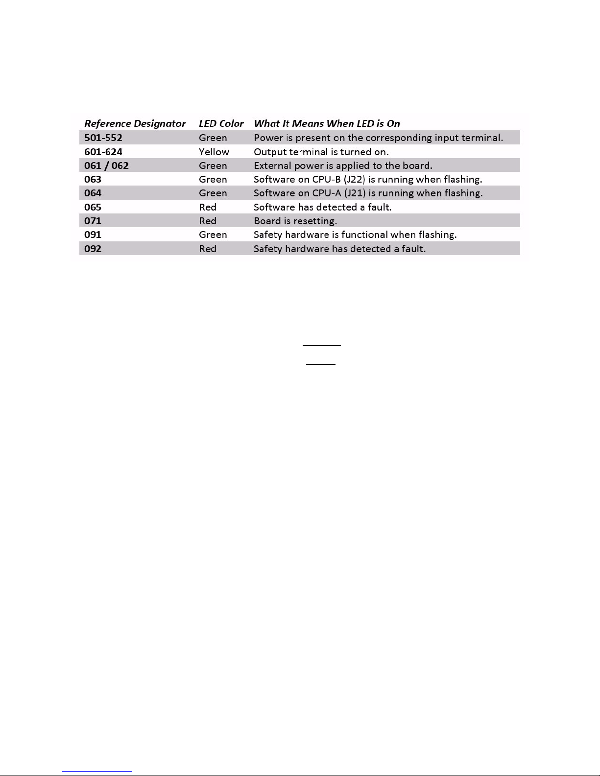
SRU LED Indicator Table
Each LED on the SRU board has a reference designator next to it. The table below
explains the function of each LED.
You will notice that the LEDs come in three colors: red, yellow, and green.
Red indicates a problem. Either a fault has been detected or the board is
resetting.
Yellow is used to indicate an active output terminal.
Green is used to show power on an input terminal, power to the board, and
as a “heartbeat” to show the software is running on the two processors.
The heartbeat is displayed by the CPU LEDs (063 and 064) which flash when
the board is functioning.
Inputs
The input terminals are labeled 501 through 548. Each terminal has a green LED
next to it which indicates when there is power present on the input. Inputs are
designed for DC current only. Putting AC current on an input will damage it.
Outputs
The yellow LED indicates the output transistor is on and current can flow
through the output terminal. The output terminal provides a reference (REF)
signal which means it will always connect to the negative side of the load. The
positive side of the load should be connected to a +24vDC power source.
** Never connect +24vDC directly to the output terminal. Without a load to
limit the current, the output transistor may be damaged. **
When the yellow LED is off, it means the output transistor is also off which
means any load connected to it will not be actuated.
12
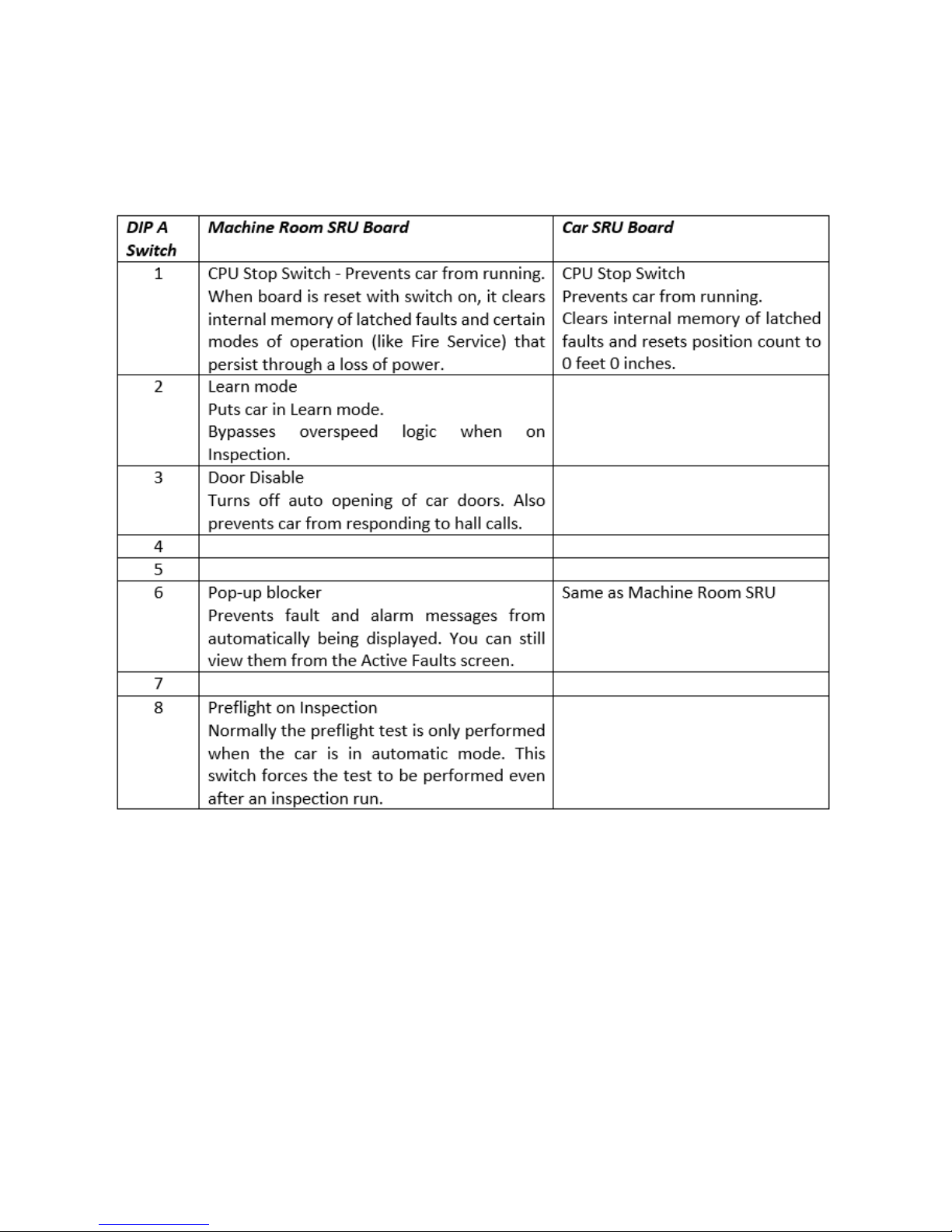
DIP Switches and Jumpers (Rev 8 bds.)
The Revision 8 SRU board has two sets of DIP switches, each containing eight
switches. The sets are labeled A and B and are located in the lower right area of
the board. The table below explains their functions.
13
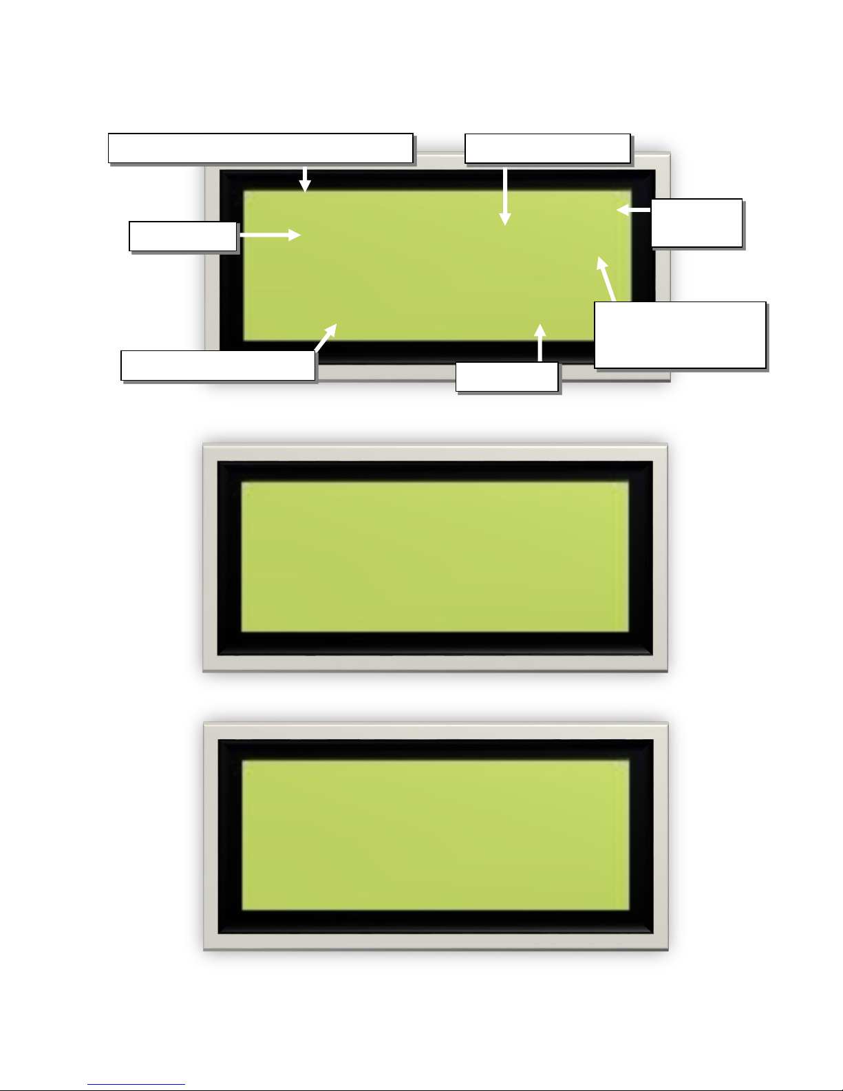
SMARTRISE SRU LCD SCREEN VIEWS
Main Me nu
*St a tus
Fa u lts
Se t up
N o r mal DZ
.. [ | ] P I : 1 T- 14
658 0 ’ 03. 3 7 ”
C M D : 0 F P M : 0
Door Zone
indicator
Current Mode (Normal, Inspection, Fire, etc)
Floor Position Indicator
Current FPM
Door Zone Step value:
T – ## (down direction)
Controller Command speed
Door position
UP [ | ] PI: 1 T- 14
GSW DCL DOL DO DC ND
DCB DOB PHE SE DPM
CAM RES RUN HVY
Normal View Screen
B + ## (up direction)
MAIN MENU SCREEN
CAR DOOR DATA SCREEN (SEE NEXT PAGE)
14
---CAR DOOR DATA---DN [ | ] PI:25 T-14
GSW DCL ... .. .. ..
... ... ... .. DPM
---CAR DOOR DATA---DN [ | ] PI:25 T-14
... ... DOL .. .. ..
... ... ... .. ...
Car Door Data Screen
Inspection (CT) DZ
These screens show the status of the door operator signals.
When the letters are visible the flag is being made.
Below are two examples of the car door status screen when Open and Closed:
Car Door Closed Car Door Open
--- CAR DOOR DATA ----
FIRST LINE
1. UP / DN – Direction of travel
2. [ | ] – Door status
3. PI: – Position Indicator
4. T-# / B+# – Magnet steps (only in door zone)
SECOND LINE
1. GSW – Gate Switch
2. DCL – Door Close Limit
3. DOL – Door Open Limit
4. DO – Door Open
5. DC – Door Close
6. ND – Nudge
THIRD LINE
1. DCB – Door Close Button
2. DOB – Door Open Button
3. PHE – Photo Eye
4. SE – Safety Edge
5. DPM – Door Position Monitor
FOURTH LINE
1. CAM – Door Cam
2. RES – Door Restrictor
3. RUN – Providing low current output to doors during travel
4. HVY – Used for heavy car/hall doors
DN [ | ] PI:25 T-14
16385 246’00.18”
CMD:-LEV FPM:-10
---CAR DOOR DATA---DN [ | ] PI:25 T-14
GSW DCL DOL DO DC ND
DCB DOB PHE SE DPM
CAM RES RUN HVY
---HALL DOOR DATA--DN [ | ] PI:25 T-14
BL BC ML MC TL TC
15
Hall Door Data Screen
DOOR ICON
MEANING
[ | ]
Doors are fully closed
[ < > ]
Doors are opening
[ ]
Doors are fully open
[ > < ]
Doors are closing or nudging
[ < | > ]
Doors are opening but gate switch is still made
< >
Doors are fully open but the Door Open output is still on
[ | | ]
Doors are ajar or not flagging properly – Unknown status
Bottom Hall Door Open –
BL / BC not flagging
---HALL DOOR DATA---
--- HALL DOOR DATA ---
FIRST LINE – SAME AS CAR DOOR DATA
SECOND LINE
1. BL / BC – Bottom Hall Lock / Bottom Close Switch
2. ML / MC – Middle Hall Lock / Middle Close Switch
3. TL / TC – Top Hall Lock / Top Close Switch
.. .. ML MC TL TC
Door Status Descriptions
16
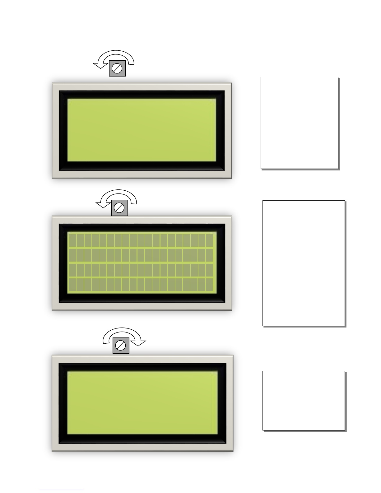
Smartrise SRU LCD Screen Adjustment
If the LCD screen is
blank but the LEDs on
the SRU board are lit
then adjust
Potentiometer R249
(located above the
LCD screen) counterclockwise.
Keep turning
Potentiometer R249
counter-clockwise until
the display comes on.
Caution: Turning
Potentiometer R249
too far will cause dark
boxes to appear around
the letters and may
burn out the LCD
screen prematurely.
N o r mal DZ
.. [ | ] P I: 1 T- 14
658 0 ’ 03. 3 7 ”
C M D : 0 F P M : 0
Turn Potentiometer
R249 clockwise until
the dark boxes
disappear but you can
still read the screen.
N o r mal D Z
.. [ | ] P I : 1 T - 14
658 0’ 03 . 3 7 ”
C M D : 0 F P M : 0
17

GENERAL INSTALLATION
While Smartrise takes every measure to provide the
customer with an out of box installation, sometimes
incomplete information leads to default values being
set on equipment and voltage settings. This is done
to protect your equipment from overvoltage issues.
[For example, the door operator for your job might
operate on 240vac but Smartrise wasn’t supplied with
that information when the job was developed,
therefore, the DR breaker (door operator voltage
supply) will be set to 120vac for safety reasons.]
Please take a moment to verify that all required
voltages for the existing equipment matches the
voltages set by Smartrise PRIOR TO POWERING UP
THE CONTROLLER. You can verify this with the
drawings provided in your job binder.
18
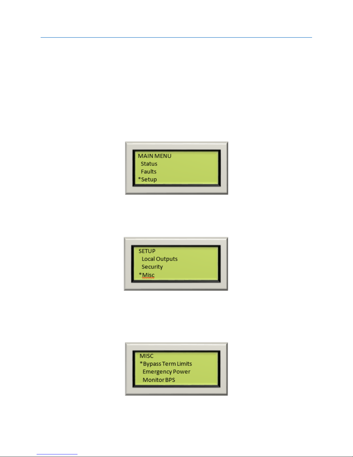
BYPASS TERM LIMITS
(Check off box when complete)
Toggle the Inspection/Normal switch to the “INSP” position.
Set BYPASS TERM LIMITS to YES:
On the Smartrise Machine Room controller board, press the Left
Arrow (ESC) button several times to get to the MAIN SCREEN.
Press the Right Arrow to go to MAIN MENU. Use the Up / Down
Arrow keys and move the asterisk to SETUP and press the enter
key.
o
Use the Up / Down Arrow keys and move the asterisk to MISC
and press the enter key.
BYPASS TERM LIMITS should be the first item listed. If it’s not, use
the Up / Down Arrow keys and move the asterisk to BYPASS
TERM LIMITS and press the enter key.
19
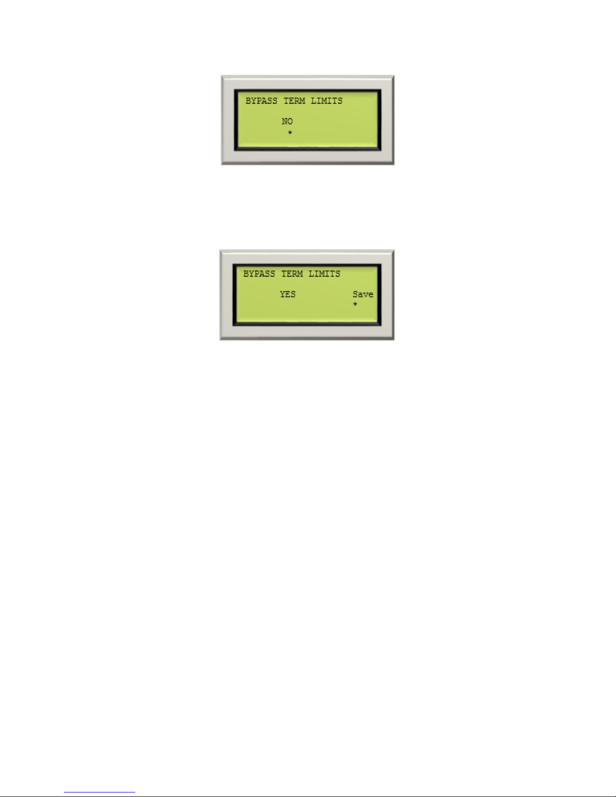
Use the Up / Down Arrow keys to change the word “NO” to “YES”.
Use the RIGHT Arrow key and move the asterisk under the
word “SAVE” and press enter.
Hit the LEFT Arrow (ESC) button several times to get to the MAIN
SCREEN.
Verify the LCD displays “Construction” Mode on the MAIN SCREEN.
Verify that the drive is not showing a fault on its display.
20

HYDRO INSTALLATION
QUICK START MANUAL
Smartrise now sends a quick start manual inside the
controller cabinet. These manuals allow the technician
to get the controller running in Construction Mode. If
the manual for the controller is missing it can be
downloaded at:
http://www.smartrise.us/support/
21
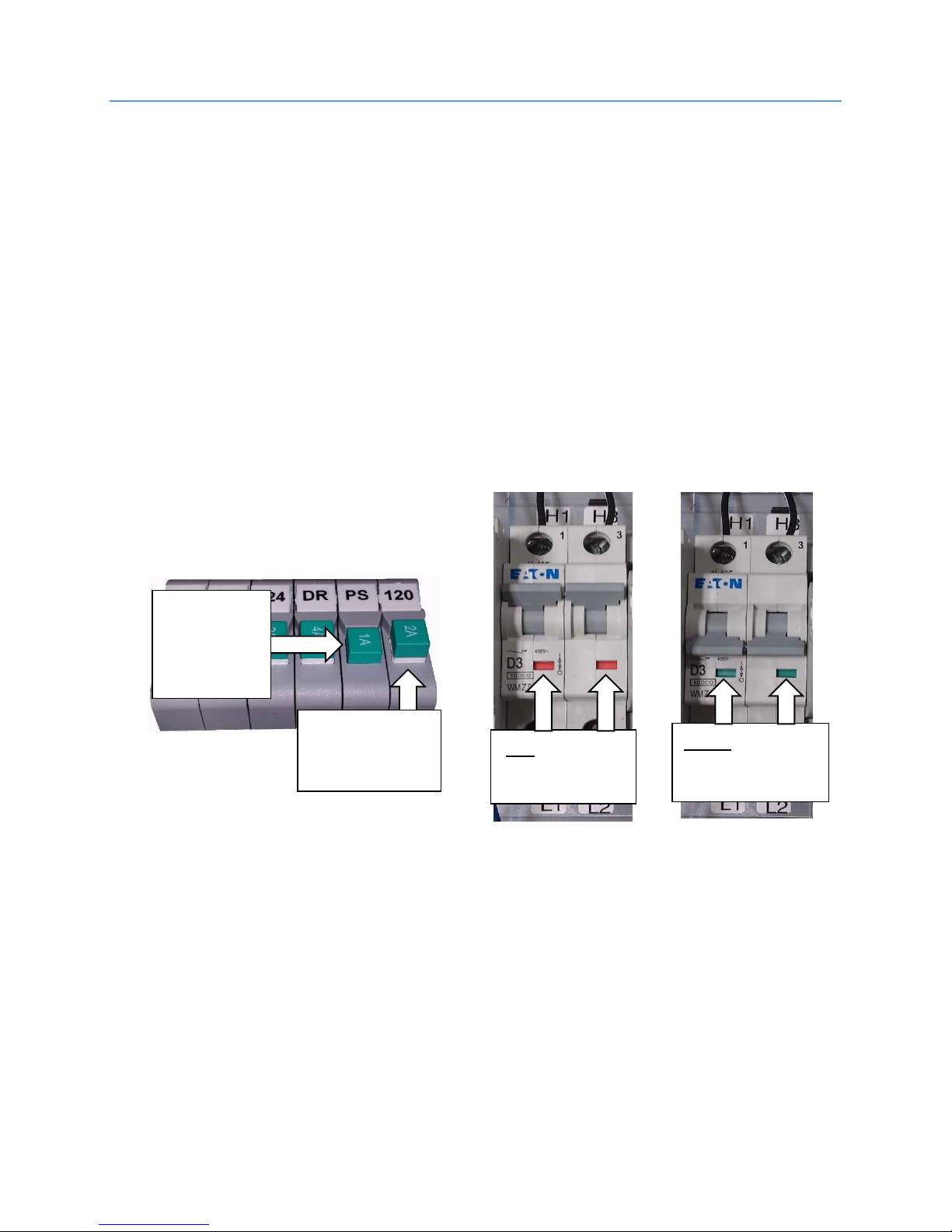
MAIN POWER SETUP
Green in Window
OFF
Red in Window
ON
Up = OFF
White showing
Down = ON
showing
Main Disconnect
Verify that main disconnect is turned off prior to installing wiring on
controller
Push Button Breakers
Verify that all green push button breakers are in the up position (OFF).
Do this for all 120vac, 240vac and 24vdc breakers.
Controller Main L1/L2 Breaker
Verify that the L1/L2 breaker is in the OFF position (green shows in
windows)
NO White
22
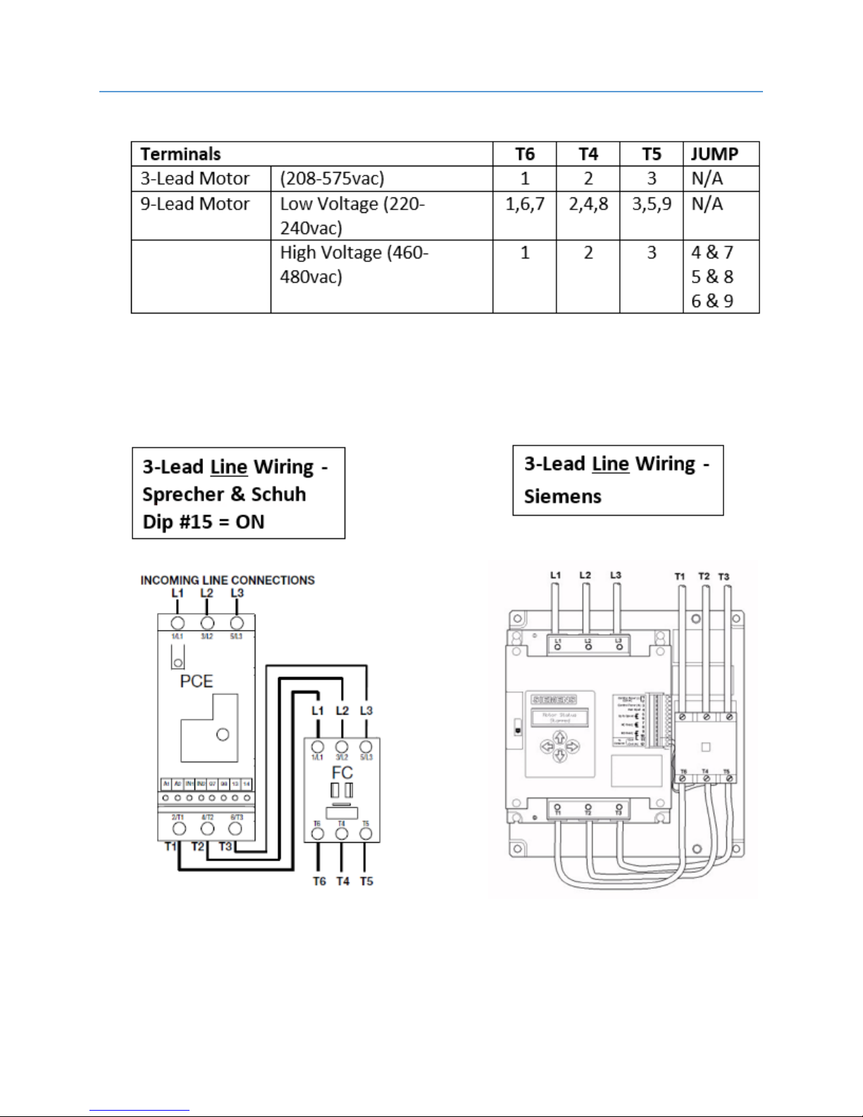
MOTOR WIRING – 3/9 LEAD MOTOR WIRING
Connect motor leads to the terminals T1/T2/T3 on the fault contactor.
23
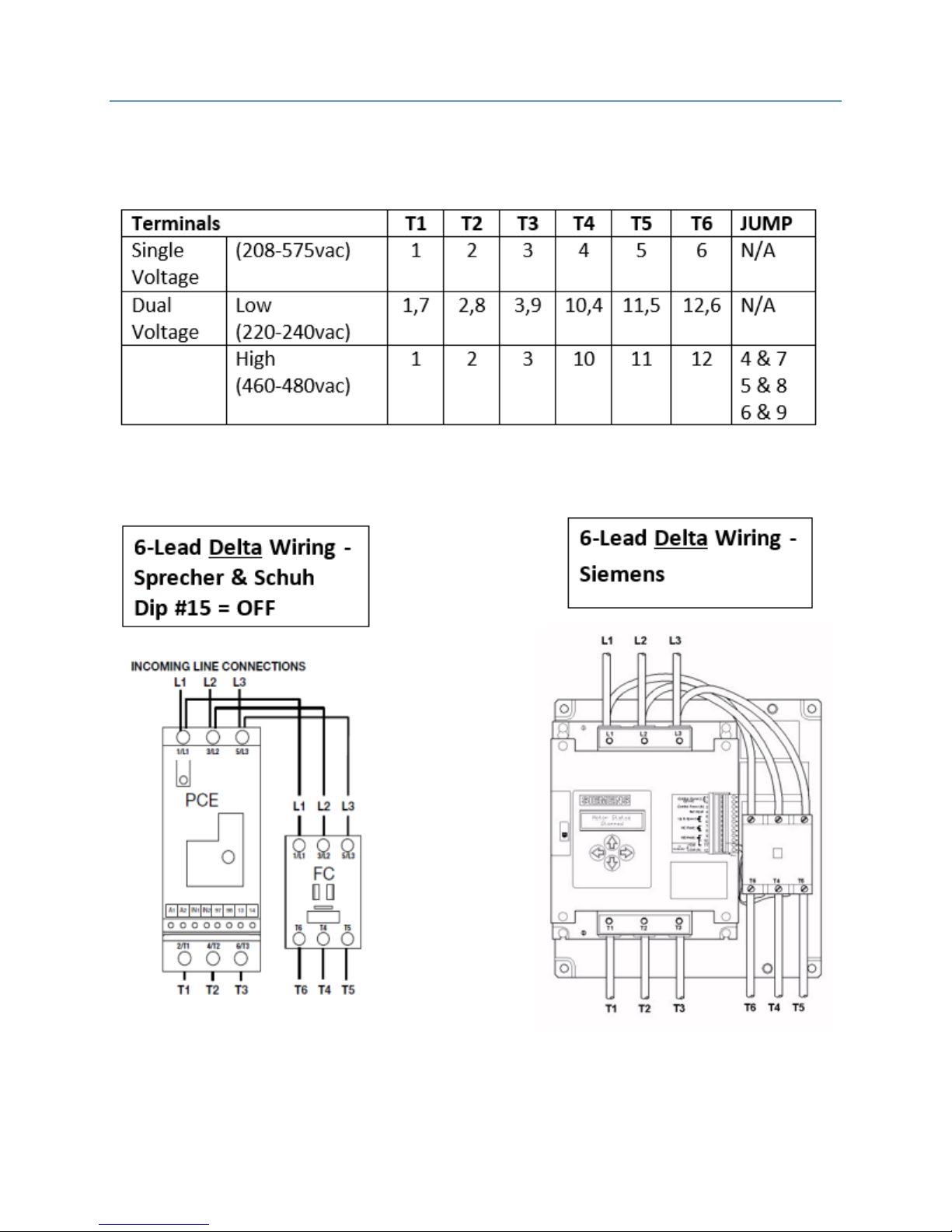
MOTOR WIRING – 6/12 LEAD MOTOR WIRING
Connect motor leads to terminals T1/T2/T3 on the softstart and
T6/T4/T5 on the fault contactor.
24
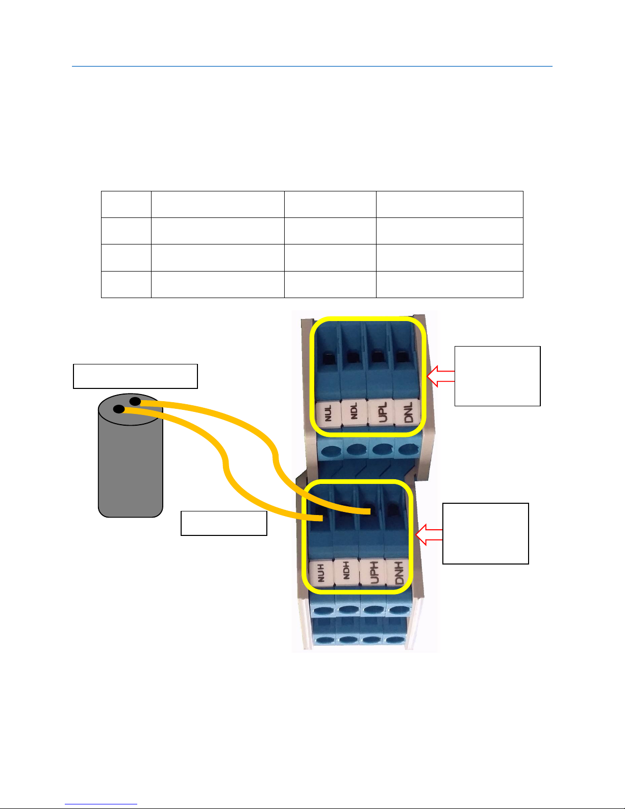
VALVE WIRING
UPH
Up High valve coil
NUH
Neutral Up High
UPL
Up Low valve coil
NUL
Neutral Up Low
DNH
Down High valve coil
NDH
Neutral Down High
DNL
Down Low valve coil
NDL
Neutral Down Low
Valve Leads
DNH / NDH
Valve Leads
DNL / NDL
Valve Leads
UP High Valve Coil
Wire the valve solenoids to the Machine Room DIN Rail terminals.
One lead of each valve solenoid goes to the “N” UP/DN (Neutral) DIN
Rail terminals and the other lead goes to the corresponding High/Low
UP/DN DIN rail terminals. See drawings for connection reference.
Refer to “Sheet 4 – Drive and Motor” for voltage requirements.
UPL / NUL
UPH / NUH
25

SOFT START SETUP – SPRECHER + SCHUH
SETUP
Verify the motor line or delta configuration and ensure that DIP switch 15 on
the Soft Starter reflects this configuration.
If the Soft Start faults out upon initial up run command, check for a red-
blinking LED on the Soft Start and count the number of times it illuminates
sequentially before a brief pause.
o The most likely cause is a line rotation issue which can be resolved by
switching T1 & T2 motor leads or change DIP switch 9 on the soft starter
to its alternate position (refer to “Sprecher + Schuh PCE Soft Start Dip
Switch Settings”).
o After changing the position of this switch, press the Reset Button adjacent
to the DIP switch group.
A noisy pump motor usually indicates a motor wiring issue. Check the pump
motor wiring and make sure it’s connected per the manufacturers
specifications.
If problems persist, refer to the Sprecher + Schuh manual for all faults
associated with the light.
26
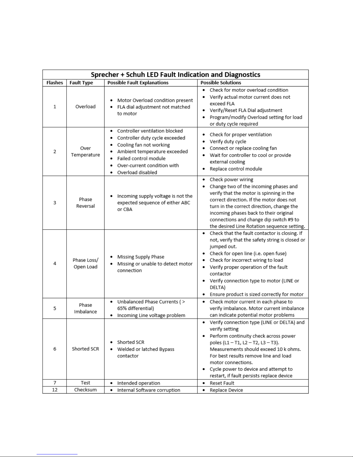
Troubleshooting
If the Smartrise controller indicates a “Drive Fault” and the softstart has the fault
LED flashing, refer to the following table for troubleshooting:
27
1) If the pump is too noisy or the motor is running in the wrong direction, it can
usually be fixed by swapping any two main lines.
2) If the car doesn’t move verify that the valve relays are turning on when a
direction is given (i.e. UPL and SM for Up direction, DNL for Down direction).
If they are then check the wiring and voltages to the valves.
3) At this point the car should be able to run using Construction Mode. Use this
mode to adjust your valves, install the traveler, tape, and the permanent
safety string.
4) Adjust your valves as required to get proper starts, stops, and run speeds.
There are two parameters that affect the pump motor during starts and
stops.
a. MAIN MENU | SETUP | TIMERS | UP TO SPEED DELAY
i. This parameter allows the pump motor to run for a specified amount
of time at the start of a run before opening the UP valves.
b. MAIN MENU | SETUP | TIMERS | PUMP OFF DELAY
i. This parameter allows the pump motor to continue running for a
specified amount of time at the end of a run after closing the UP
valves.
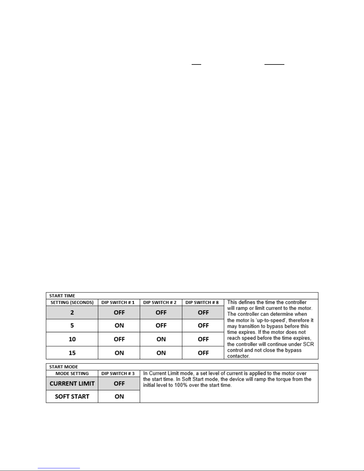
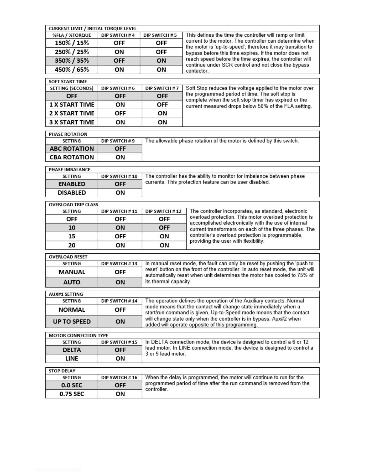
Sprecher + Schuh PCE Soft Start Dip Switch Settings
The PCE elevator controller is programmed through dipswitches located on
the front of the controller. Default settings are indicated by the shaded
areas.
28
29
 Loading...