

SmartPTT RG-1000e User Manual
RG-1000e Remote Gateway
User Guide
June 2018
R2.2.2 v2

Table of Contents
Table of Contents
Foreword
Revision history
Compliance with international standards
Introduction
1 System purpose
2 System structure
2.1 Technical specification
2.2 Delivery set
3 Installation and connection
3.1 Front panel
3.2 Rear panel
3.3 Fisrt time settings, connection and operation check
4 Examples of using RG-1000e
4.1 Conventional Mode
4.2 Capacity Plus legacy trunking network
4.3 Capacity Plus trunking network with NAI Data (hybrid mode)
4.4 Capacity Plus multi-site trunking network with NAI Data (hybrid mode)
4.5 I\O mode
4.6 Bridge mode
5 Storage and transportation conditions
6 Manufacturer warranty
6.1 What this warranty covers and for how long
6.2 General provisions
6.3 How to get warranty services
6.4 What this warranty does not cover
6.5 Contacts
Appendix I Pin numberings and diagrams of the interface cables
Appendix II Mounting elements
Appendix III Power cable preparation
2
3
4
5
6
8
9
11
12
12
13
14
17
17
20
21
23
24
26
27
28
28
28
28
29
29
30
37
38
RG-1000e Remote Gateway R2.2.2 v2 User Guide

Foreword
Disclaimer
The information in this document is carefully examined, and is believed to be entirely reliable. However, no
responsibility is assumed for inaccuracies.
Furthermore, Elcomplus reserves the right to make changes to any products herein to improve usability, function,
or design without prior notice.
Elcomplus does not assume any liability arising out of the application or use of any product; nor does it cover any
license under its patent rights nor the rights of others.
Trademarks
MOTOROLA SOLUTIONS, the Stylized M logo, MOTOTRBO are registered in the US Patent & Trademark Office.
SmartPTT and RG-1000e are the property of Elcomplus. All other product or service names are the property of
their respective owners.
2
User GuideRG-1000e Remote Gateway R2.2.2 v2

Revision history
Date
Version
Description
May, 2017
RG-1000e Remote Gateway, R1.0
Initial version.
July, 2017
RG-1000e Remote Gateway, R1.1
Updated release.
October, 2017
RG-1000e Remote Gateway, R2.0
Updated release. Updated technical parameters.
February, 2018
RG-1000e Remote Gateway, R2.2
Updated release. Updated technical parameters.
Added new operational mode.
June, 2018
RG-1000e Remote Gateway, R2.2.2
Updated release. Radio connection cable
schematics updated. Delivery set info updated.
"Operating principles" chapter is deleted.
The following table contains the history of updates to the RG-1000e Remote Gateway user guide.
3
User GuideRG-1000e Remote Gateway R2.2.2 v2

Compliance with international standards
This device complies with Part 15 Subpart B of the FCC CFR 47 Rules. Operation is subject to the following two
conditions:
(1) this device may not cause harmful interference, and
(2) this device must accept any interference received, including interference that may cause undesired operation.
This device complies with EN55032/CISPR32 EN55024/CISPR24.
This device complies with DIRECTIVE 2011/65/EU (RoHS 2)
This device complies with IEC/EN60950-1.
This device complies with TR EAC 020/2011 "Electromagnetic compatibility of technical means", GOST CISPR32-
2015, GOST CISPR 24-2013.
4
User GuideRG-1000e Remote Gateway R2.2.2 v2

Introduction
This user guide describes the purpose, characteristics, functioning principles, setup and configuration of RG1000e . This guide is aimed at engineers responsible for installation and maintenance of the SmartPTT dispatch
system and the MOTOTRBO equipment.
It is assumed that users responsible for setting up RG-1000e are familiar with the following:
· The principles of building IP networks and radio networks using the MOTOTRBO equipment produced by
Motorola, and
· SmartPTT software developed by Elcomplus.
It is strongly recommended that you read this user guide you start work with the RG-1000e!
Note that improper testing, operation, maintenance, installation, alteration, modification, or adjustment
causes warranty cancellation.
5
User GuideRG-1000e Remote Gateway R2.2.2 v2
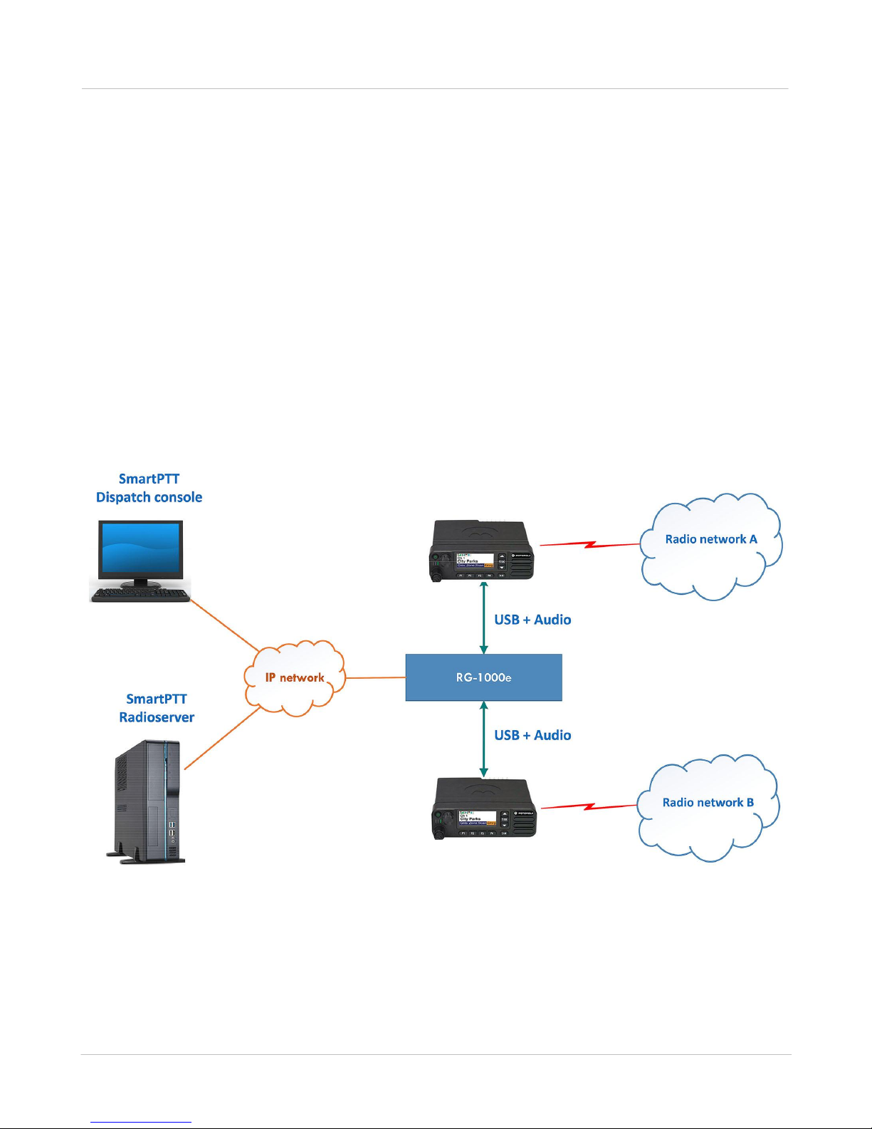
1 System purpose
Fig. 1 MOTOTRBO control stations: remote connection to SmartPTT dispatch system
The RG-1000e is used in SmartPTT dispatch systems to provide remote control for the MOTOTRBO control
station(s) or radios through the SmartPTT Radioserver (hereinafter referred to as radioserver) in the corporate IP
network or on the Internet. It must be used with MOTOTRBO Radios: EMEA region DM46**e, DM44**e, DM46**,
DM44**, DM2600 ; APAC region XiR M8600i, XiR M8600, XiR M6660 ; NA region XPR 5***e, XPR 5***, XPR 2500
; LA region DGM 8***e, DGM 5***e, DGM 8***, DGM 5***, DEM500.(*)
The RG-1000e provides conversion of audio signals and radio control commands into IP packets and
transmission of these packets over the network.The RG-1000e is an alternative to direct connection of control
stations to the radioserver via a USB interface.
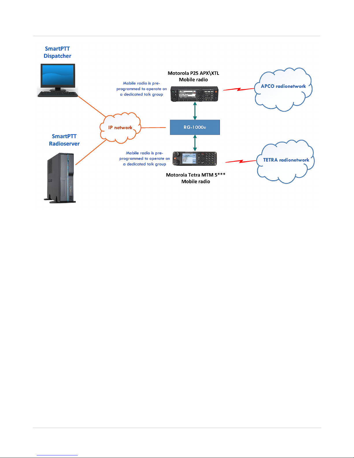
The RG-1000e with firmware version R2.2 or later may be used for connection of non-Mototrbo radios to the
SmartPTT radioserver. Mobile radios and\or repeaters (analog or digital) are connected to the RG-1000e using 5
wires: PTT, CSQ, RX Audio, TX Audio and GND. This connection mechanism provides voice exchange between
SmartPTT Dispatchers and talk-groups of non-Mototrbo radio networks.
The figures below show examples of a remote control station using the RG-1000e .
6
* Note low tier Mototrbo radios DM1400/DM1600, CM200d/CM300d, DEM300/DEM400, XIR M3188/XIR M3688
and legacy (the first generation) Mototrbo radios can not be used with RG-1000e .
User GuideRG-1000e Remote Gateway R2.2.2 v2
7
Fig. 2 non-MOTOTRBO control stations: remote connection to SmartPTT dispatch system
User GuideRG-1000e Remote Gateway R2.2.2 v2

2 System structure
The system of control station remote management consists of the following components:
· RG-1000e
· Radio connected to the RG-1000e
· SmartPTT software based on the Client–Server technology
The RG-1000e is connected and interacts with the SmartPTT server-based application that is used for controlling
it. For establishing an IP network connection, the RG-1000e is equipped with the 10BASE-T/100BASE-TX
Ethernet interface with the cable type autodetection. To provide interaction between the system components, the
RG-1000e and the radioserver are assigned static IP addresses and TCP and UDP/RTP port numbers. They are
used for sending radio control commands and audio transmissions from the dispatch console. The RG-1000e can
be used in the following cases:
· As a remote dispatcher's workplace outstation in digital networks without repeaters (Direct Mode
communication).
· In conventional or trunking MOTOTRBO networks where direct IP connection to repeaters is unavailable.
8
· In MOTOTRBO networks where connection to repeaters is established according to the hybrid scheme (data
calls are performed via the NAI interface of the repeater, voice calls are performed via the control station.
· In conventional or trunking non-MOTOTRBO networks where the RG-1000e is connected to control stations
and\or repeaters using GPIO lines.
The system offers the following advantages:
· You can organize a dispatch system in the networks where direct connection of the dispatch system to the
MOTOTRBO repeaters via an IP network is unavailable.
· You do not have to instal the radioserver in close proximity to the control stations within the radio network
coverage area.
· You can avoid interference and induced noise between the control stations located close to each other.
When planning the system, it must be taken into account that the packet delivery delay in the IP network leads to
the corresponding delay in radio responses to control commands and voice calls.
User GuideRG-1000e Remote Gateway R2.2.2 v2
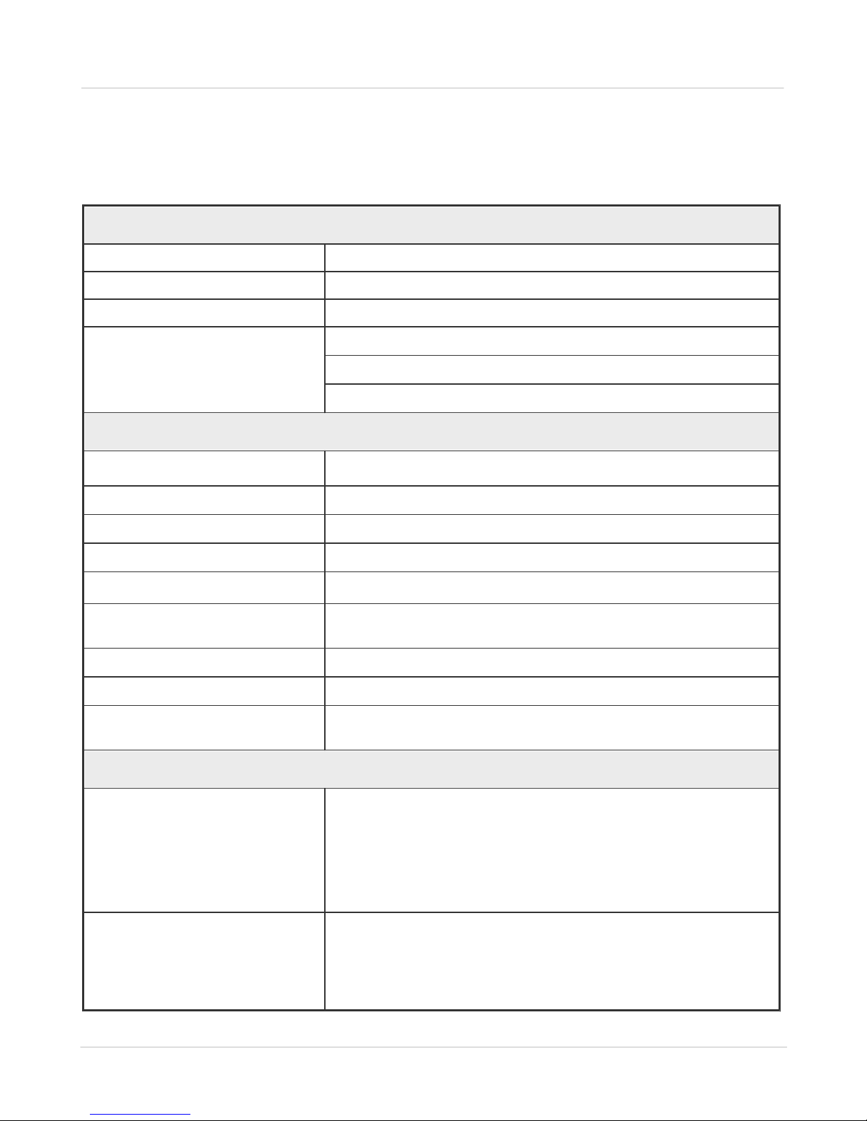
2.1 Technical specification
Network interface parameters
Connector
RJ45
Standard
10BASE-T (IEEE 802.3) / 100BASE-TX (IEEE 802.3u)
Supported TCP/IP protocols
UDP, ICMP, IPv4, ARP
Operation mode auto-selection
Transmission rate—10/100 Mbps
Operation mode—duplex/half-duplex
Cable type —Auto-MDI/MDI-X
Radio interface parameters
Number of ports for radio connections
Two ports (can be used simultaneously and independently from each
other)
Voice ADC-DAC conversion
768 kbps (48 kHz x 16 bits) PCM, duplex
Frequency band of voice channel
20–3600 Hz
VoIP codec
64 kbps (G711 A-Law/Mu-Law)
Transport protocol of control channel
UDP and TCP
Required bandwidth for control
channel
~ 15 kbps for each IP connection
Transport protocol of voice channel
UDP and RTP
Required bandwidth for VoIP channel
~128 kbps for each IP connection
Time delay/latency (SmartPTT
Radioserver <-> RG-1000e), ms
Up to 1250 ms one-way (2500 ms round-trip)
Support of radio operation modes
MOTOTRBO radio models
EMEA region: DM4600e, DM4400e, DM4600, DM4400 families, DM2600
APAC region: XiR M8600i, XiR M8600, XiR M6660
NORAM region: XPR 5000e, XPR 5000 families, XPR 2500
LATAM region: DGM8000e, DGM 5000e, DGM 8000, DGM 5000 families,
DEM500
Radio operation modes
Digital Mototrbo / Analog MOTOTRBO mode
I/O mode (connection to non-MOTOTRBO devices over GPIO) for talk
group voice exchange
Bridge mode (without using SmartPTT)
Technical parameters of the RG-1000e are listed in the following table
Table 1 RG-1000e technical parameters
9
User GuideRG-1000e Remote Gateway R2.2.2 v2
2.1 Technical specification
MOTOTRBO network topologies
Talkaround mode
Single repeater
Multisite conventional network (IP Site Connect)
Single site trunking network (Capacity Plus)
Multisite trunking network (Linked Capacity Plus, Capacity Max)
Power supply
Supply voltage
11–15.0 VDC, power can be applied via Power socket and/or radio
Radio1 socket and\or radio Radio2 socket
Power consumption
200 mA or less
Design
Dimensions
180x144x30 mm
Ethernet connector
RJ45 8P8C (8 pins)
Radio connector
3M 10126-*** jack (26 pins)
Power connector
Phoenix Con PTSM 0.5-3 (3 pins)
Audio connector
Phoenix Con PTSM 0.5-2 (2 pins)
Terminal connector
USB mini-B jack (4 pins)
Operating conditions
Operating temperature range
–4° to 140°F (–20° to +60°C)
Relative humidity
Up to 85% at 86°F (30°C)
Operating hours
24x7
Control terminal
Interface port
USB 1.0 (12 MBps), Device port
Software
RG-1000e Customer Programming Software (RG-1000e CPS)
10
User GuideRG-1000e Remote Gateway R2.2.2 v2

2.1 Technical specification
· RG-1000e
—1 pcs.,
· Interface cable*
—1 pcs.,
· FTP5E cable, 6.56 feet (2 m)
—1 pcs.,
· DC power cable
—1 pcs.,
· Mounting kit:
o bracket
—2 pcs.,
o M3x6 screw
—4 pcs.,
o M5x10 screw
—2 pcs.,
o 5x20 self-tapping screw
—4 pcs.,
· USB cable A-miniB, 1 m.
—1 pcs.
11
2.2 Delivery set
The RG-1000e delivery set includes the following components:
* One interface cable is included in the RG-1000e delivery set (for MOTOTORBO DM 4600e/DM 4400e, XiR
M8600i, DGM 8000e/DGM 5000e radio families).
Optionally, an additional interface cable can be purchased.
Interface cables for DM 2600, XiR M6660, XPR 2500, DEM 500 radios can be included in the delivery set on
request.
Interface cables for non-MOTORBO radios can be included in the delivery set on request.
For information on prices and availability of additional interface cables, contact us on www.smartptt.com
User GuideRG-1000e Remote Gateway R2.2.2 v2
 Loading...