

Smartpond Skmbx, Skmbxca User Manual
MODEL # SKMBX / SKMBXCA
PACKAG E CONTENTS
PREPARATION
Part
Description
Quantity A Tank
1 B Leaf basket
1
C
Cover
1
D
Adapter
2
E
Coupler
1
F
Gasket
1
G
Tubing
1 H Door w/foam
1
I
Screw
12 J Nut plate
1 K Face Plate
1
Questions, problems, m i ssing parts? Before returning
A B D
E
C
REMINDER
BEFORE RETURNING TO STORE.
®
D
F
G H I J K
Pond Skimmer up to 3000 gallons
CALL 1-888-755-4497
to your retailer, call our cust om er ser vice department at
1-888-755-4497, 8 a.m.-6 p.m., EST, Monday-Friday, or
email us at customercare@smart-pond.com.
Before beginning assem bl y of product, make sure all parts are pr esent. Compare parts wit h package
contents list and diagram above. If any part is missing or damaged, do not attempt to as semble, install or
operate the product. Contact customer service for replacement parts.
• Estimated Assembly Ti me: 60 minutes.
• Tools required for assem bly: Shovel, Carpenter’s level, Caulking gun, Liner sealant. 2 Temporary nails,
Philipshead screwdriver, Utility knife,
WWW.SMART-POND.COM
PLEASE CALL 1-888-755-4497 BEFORE RETURNING TO THE STORE.
ASSEMBLY INSTRUCTIONS
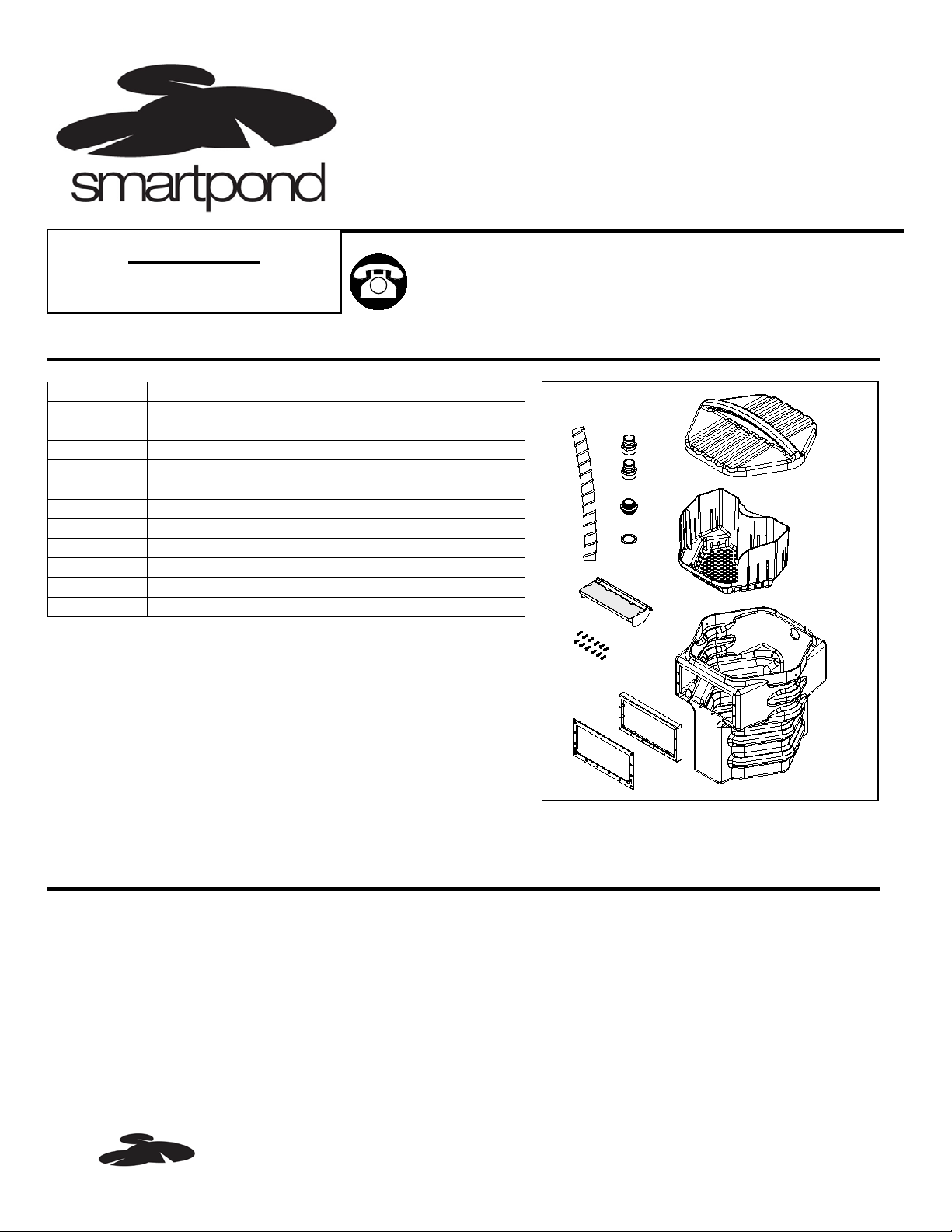
Maximum
water level
20”
20”
16”
Apply sealant
1. Dig a 20 inches long x 20 inches wi de hole at the perimeter of
the pond where you will be loc ating you skimmer. The dept h
of the hole depends on the maxim um water level in your
pond, the bottom of the hole should be 16 inches deep bellow
the maximum water level, this will allow the water level to
drop 3 inches without any loss of s ki m mer function. Fig. 1
NOTE: If you are installing your skimmer in an existing pond,
Drain the pond down 1 to 2 feet befor e starting.
Fig. 1
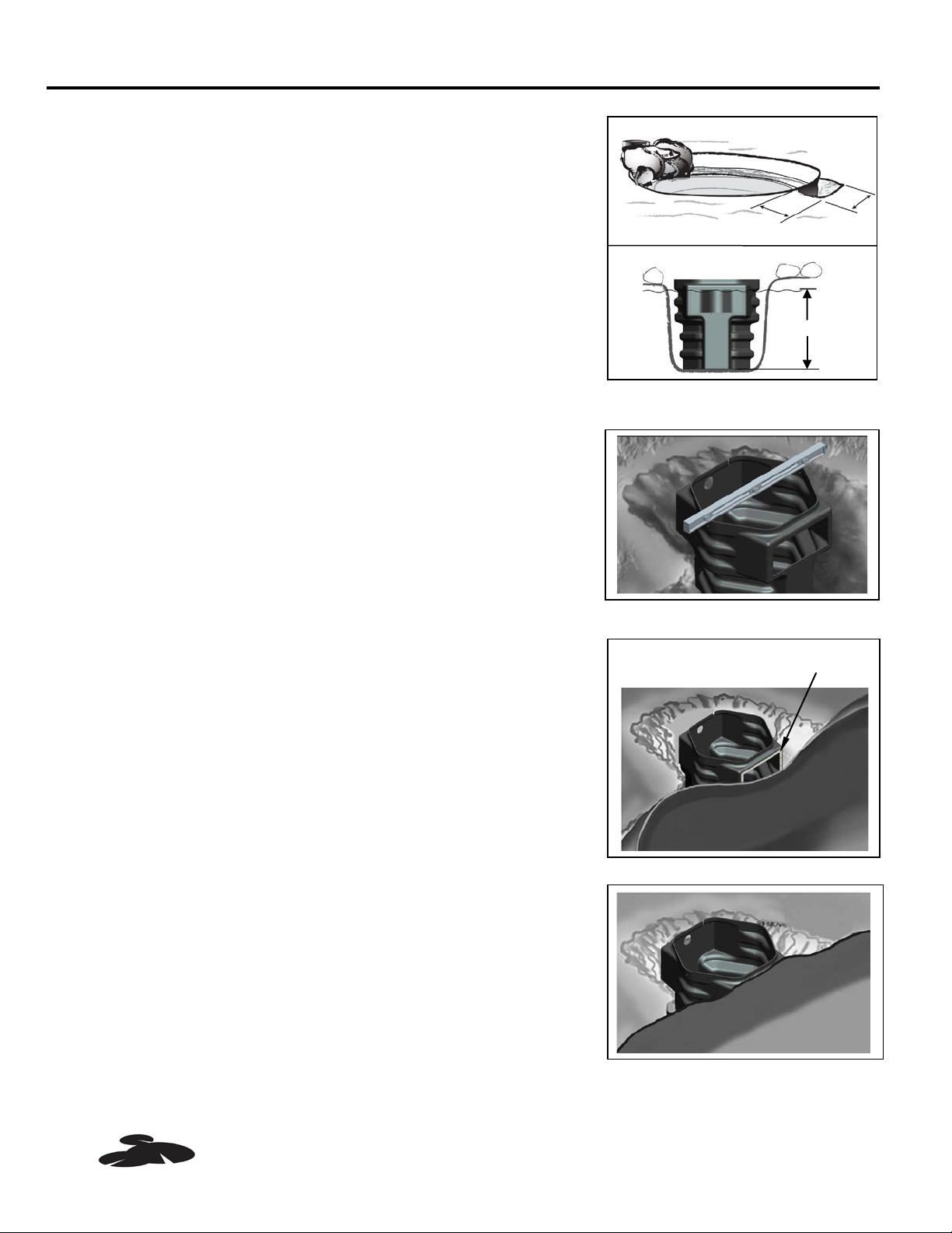
2. Set the skimmer in the hole and ch eck for fit and level. Fig. 2
Fig. 2
3. Carefully clean and rinse the liner inside and out w ith water,
then dry it with paper towe ls or a clean cloth. The surface to
be sealed must be clean and dr y for the sealer to bond
properly. Apply a 1/4” bead of the sealant around the front
tank opening , making sur e t her e ar e no spaces or voids in
the bead. Fig. 3
Fig. 3
4. Align the liner on the front fac e of t ank, make sure the liner
sits flat on the front face of tank whthout wrinkling or pulling.
Fig. 4
Fig. 4
PLEASE CALL 1-888-755-4497 BEFORE RETURNING TO THE STORE.
WWW.SMART-POND.COM
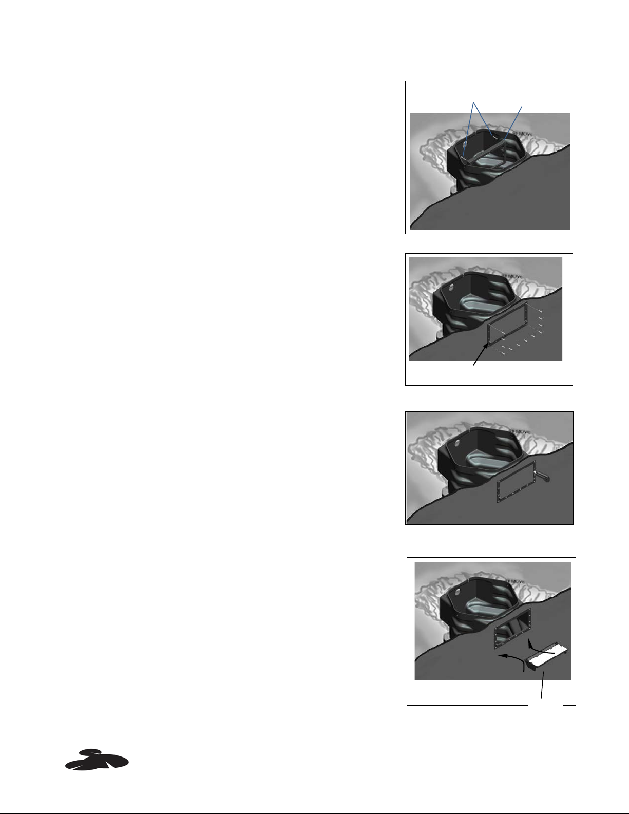
Door hinges
Temporary nail
Nut plate
Foam
Fig. 5
NOTE: Door hinges positioned on face plate must face out
and at the bottom. Do not use power drill for screws.
Fig. 6
Fig. 7
NOTE: Foam side faces up.
Fig. 8
WWW.SMART-POND.COM
5. Insert 2 temporary nails in to top corner hole of the nut plate
and tank, then holding the nails in place with hand, push the
nail through the liner. Fig. 5
6. Assembly the face plate int o t he nut plat e t o securely seal the
liner to the tank, carefullly inst al l t he scr ews snug, finally
remove the temporary nai ls and attach the last two screw .
Fig. 6
7. Use knife to cut and remove liner sect ion from opening, wipe
off the excess sealant aro und t he opening. Fig. 7
8. Install door by flexing hing e pin s inw ard, then snapping into
door opening. Make sure t he door opens and closes without
interfearence. Fig. 8
PLEASE CALL 1-888-755-4497 BEFORE RETURNING TO THE STORE.
 Loading...