

Page 1

SmartPay Plus
Quick Reference Guide
Sammi Paytech co.,ltd
Ver 1.0 June. 2010
Page 1 6/24/2010
Page 2

Disclaimer
SmartPay Plus are registered trademarks of
SAMMIPAYTECH Co., Ltd.
All other brand names, product names, or trademarks belong to their respective
holders.
Head Quarters
SAMMIPAYTECH Co.,Ltd.
496 Woncheon-dong, youngtong-gu, Suwon-shi, Kyungki-do, Korea
Tel. 82 -31-211-5596~7 / Fax. 82-31-217-8254
Web. www.sammipaytech.com
Sales Office
1057-3 Namhyun-dong, Goanak-gu, Seoul-shi, Korea
Email. sales@smartpaytech.com
Web. www.sammipaytech.com
.
Page 2 6/24/2010
Page 3

FCC Compliance Information
This equipment has been tested and found to comply with the limits
for a Class A digital device, pursuant to part 15 of the FCC Rules.
These limits are designed to provide reasonable protection against harmful interference when
the equipment is operated in a commercial environment. This equipment generates, uses, and
can radiate radio frequency energy and, if not installed and used in accordance with the
instruction manual, may cause harmful interference to radio communications. Operation of this
equipment in a residential area is likely to cause harmful interference in which case the user
will be required to correct the interference at his own expense.
Caution
Modifications not expressly approved by the party responsible for compliance could void the user’s
authority to operate the equipment
This device complies with Part 15 of FCC Rules. Operation is subject to the following
twoconditions
(1) the device may not cause interference, and
(2) the device must accept anyinterference, including interference that may cause undesired operation of
this device.
:
IMPORTANT NOTE:
FCC RF Radiation Exposure Statement:
This equipment complies with FCC RF radiation exposure limits set forth for an uncontrolled environment.
This equipment should be installed and operated with a minimum distance of 20 centimeters between the
radiator and your body.This transmitter must not be co-located or operating in conjunction with any other
antenna or transmitter.
NOTE:
CAUSED BY UNAUTHORIZED MODIFICATIONS TO THIS EQUIPMENT. SUCH MODIFICATIONS
COULD VOID THE USER’S AUTHORITY TO OPERA TE THE EQUIPMENT.
THE MANUFACTURER IS NOT RESPONSIBLE FOR ANY RADIO OR TV INTERFERENCE
Page 3 6/30/2010
Page 4

Table of Contents
Introduction................................................................................................................................................... 6
Chapter 1 Get to know more about SmartPay Plus....................................................................................... 7
1.1 Make sure you have everything....................................................................................................... 7
1.2 Appearance........................................................................................................................................... 8
1.2.1 Front side.................................................................................................................................. 8
1.2.2 Rear side........................................................................................................................................ 9
1.2.3 Top & Bottom side................................................................................................................ 10
1.2.4 Left and Right side...................................................................................................................11
Chapter 2 Hot Keys...................................................................................................................................... 12
2.1 Keys............................................................................................................................................... 12
2.2 Front panel keys description.......................................................................................................... 12
Chapter 3 Power settings and connections.................................................................................................. 14
3.1 Power management....................................................................................................................... 14
3.2 Install battery in SmartPay Plus..................................................................................................... 14
3.3 Battery charging using power adapter........................................................................................... 14
3.4 Power settings on Windows CE..................................................................................................... 14
3.5 Turn on SmartPay Plus.................................................................................................................. 16
3.6 Turn off SmartPay Plus.................................................................................................................. 16
Chapter 4 Operation modes......................................................................................................................... 17
4.1 Normal mode ................................................................................................................................. 17
4.2 Suspend mode............................................................................................................................... 17
Chapter 5 Resetting SmartPay Plus ............................................................................................................ 18
5.1 Warm Reset................................................................................................................................... 18
5.2 Cold Reset..................................................................................................................................... 18
5.3 Difference between cold and warm reset ...................................................................................... 20
Chapter 6 Configuring SmartPay Plus......................................................................................................... 20
6.1 Main Display screen description.................................................................................................... 20
6.2 Calibrating the touch screen.......................................................................................................... 22
6.3 Setting up WLAN card ................................................................................................................... 23
6.4 Volume / sound control.................................................................................................................. 24
6.5 Date/Time settings......................................................................................................................... 25
Chapter 7. Applications and operations....................................................................................................... 25
7.1. Scanning Barcode (1D/2D CCD type scanner )............................................................................ 25
7.2 1D/2D Scanner configuration settings ............................................................................................. 25
7.3 Demonstration program for 1D / 2D Scanner................................................................................ 25
7.4 Printer demonstration program..................................................................................................... 25
7.5 RFID demonstration program......................................................................................................... 25
Run RFDDemo Program .......................................................................................................................... 25
Page 4 6/24/2010
Page 5

Version information................................................................................................................................... 25
Main Screen.............................................................................................................................................. 25
Select Tag................................................................................................................................................. 25
TagInfo (EAS/AFI/DSFID)......................................................................................................................... 25
Detail......................................................................................................................................................... 25
ReadTagAll............................................................................................................................................ 25
OneReadTag......................................................................................................................................... 25
WriteTag................................................................................................................................................ 25
LockTag................................................................................................................................................. 25
7.6 Finger Print .................................................................................................................................... 25
7.7 Camera.......................................................................................................................................... 25
7.8 Operating System upgrade manual............................................................................................... 25
Chapter 8. Accessories and peripheral devices........................................................................................... 25
8.1 Using Stylus pen............................................................................................................................ 25
8.2 Using CDMA (Code Division Multiple Access) module (Optional)................................................. 25
Chapter 9. PC Interface................................................................................................................................ 25
9.1 Ms ActiveSync Installation............................................................................................................. 25
9.2 USB ActiveSync............................................................................................................................. 25
Page 5 6/24/2010
Page 6

Introduction
This quick reference guide allows you to use all the advanced features of SmartPay Plus effectively.
Please go through it once before using SmartPay Plus handheld terminal.
Page 6 6/24/2010
Page 7

Chapter 1 Get to know more about SmartPay Plus
1.1 Make sure you have everything
SmartPay Plus main unit
Stylus Pen
Standard battery pack (
Power adapter
Synchronization cable (USB cable)
Backup battery 110mA Lithium-ion (Embedded)
Optional accessories
Docking station (Desktop and vehicle)
Protective carrying case
Synchronization cable (Serial)
1800 mAH Li-ion)
Page 7 6/24/2010
Page 8

1.2 Appearance
1.2.1 Front side
Features and description
Features Function / Description
Printer Machanism 2inch thermal type printer and 30Ø Roll paper
RFID Reader To read the contactless IC Card by touching the printer cover
Communication &
It is blinking while running
Scanner LED indicator
Finger Print Sensor To scan and verify finger print as the registered one.
LCD touch screen display It shows the running application and desktop,
Stylus can be used to select the application and inputting data
on touch screen
Page 8 6/24/2010
Page 9

1.2.2 Rear side
Rear panel features
Name Function / Description
Stylus pen To use for touch screen
Hand strap To hold SmartPay Plus unit
Main Battery To give Dc power to SmartPay Plus
Battery lock switch To lock/unlock battery pack
Reset key To perform warm and cold reset
Camera & Camera flash 2.0 Mega Pixel.
Page 9 6/24/2010
Page 10

1.2.3 Top & Bottom side
Features and description
Features Function / Description
1D Scanner window While scanning the scanner beam is emitted and absorbed
through this window
I/O port To connect to other devices using synchronization cable
Page 10 6/24/2010
Page 11

1.2.4 Left and Right side
Features and description
Features Function / Description
Left Scan key To scan the barcode user should press this key also known
was hardware scan key.
Right Scan key To scan the barcode user should press this key also known
was hardware scan key.
Page 11 6/24/2010
Page 12

2.1 Keys
Chapter 2 Hot Keys
2.2 Front panel keys description
Key name Functions description
Navigation keys Default -- To move the cursor left, right, up and down
In Function mode
<up> To increase intensity of backlight
<down> To reduce intensity of backlight
<right> To increase speaker sound
<left> To decrease speaker sound
Power key To turn SmartPay Plus (sleep / awake) and LCD backlight on/off
TAB key Functions same as “Tab” key on keyboard in windows mode
In function mode used to open application 1 or defined application
Alpha key To switch to alphabet mode
Function key Other keys in combination with “Func” key have secondary functions
Enter key Functions same as “Enter” key on keyboard in windows mode.
In function mode works as stylus calibration.
Alpha-Numeric keys To print various characters (0 – 9, a – z etc) in editor window
Home key To clear desktop
In function mode to turn wireless on/off.
Alpha-numeric Keys functions in different modes
Page 12 6/24/2010
Page 13

Key In numeric mode In function mode In alpha mode
<1> Prints number 1 on editor screen Functions as “Ctrl” key on
keyboard
<2> Prints number 2 on editor screen Functions as “Alt” key on
keyboard
<3> Prints number 3 on editor screen Functions as “Del“ key on
keyboard
<4> Prints number 4 on editor screen To open application 2 or
defined application
<5> Prints number 5 on editor screen To open application 3 or
defined application
<6> Prints number 6 on editor screen To open application 4 or
defined application
<7> Prints number 7 on editor screen Functions as “+” key on
keyboard
<8> Prints number 8 on editor screen Functions as “-“ key on
keyboard
<9> Prints number 9 on editor screen Functions as “Insert“ key on
To switch to Caps lock
mode
To print a/ b/c on
editor screen
To print d/e/f on editor
screen
To print g/h/i on editor
screen
To print j/k/l on editor
screen
To print m/n/o on
editor screen
To print p/q/r/s on
editor screen
To print t/u/v on editor
screen
To print w/x/y/z on
keyboard
<0> Prints number 0 on editor screen Functions as “/“ key on
keyboard
<.> Prints number decimal/period on
editor screen
Functions as “*“ key on
keyboard
LED colors and description
Name On state
Battery charging LED
Blinking blue – Low battery (below 10%)
Green – Fully charged
Red – While charging
Wireless LAN indicator LED
Scanner LED
Blinking green - Wireless LAN on
Red - Scanner result (error)
Green - Scanner result (success)
editor screen
To print blank space
on editor screen
To print .,:@ on editor
screen
Page 13 6/24/2010
Page 14

Chapter 3 Power settings and connections
3.1 Power management
SmartPay Plus works on DC power.
A standard lithium ion battery pack (7.4V, 1800 mAH) is provided for Dc power input to SmartPay Plus.
Charging time is 5 hours with 10 operation and 100 standby hours.
Battery low (below 10%) condition is indicated with Blue power LED.
In order to support SmartPay Plus in low battery state, there is an inbuilt 110 mAH rechargeable backup
battery provided, it has backup time of 2.7 hours without main battery (in sleep mode).
For charging both main and backup batteries an AC adapter 100-240 V 50/60 Hz and 9 V/ 2~3A DC output
is provided with power cord.
Note: Never use SmartPay Plus unit without main battery.
3.2 Install battery in SmartPay Plus
Detach the hand strap end on rear side of SmartPay Plus. Unlock the Battery lock switch.
Slid the battery latch upwards and insert the battery pack given with the correct polarity.
Note: Only use the batteries which are provided for SmartPay Plus units.
3.3 Battery charging using power adapter
Connect power cord from AC power supply to AC adapter/charger.
Connect Ac adapter to SmartPay Plus through DC input jack present on bottom side.
While charging power LED will be red, after fully charged it will be green.
Backup battery also gets charged during this time.
Charging time is 5 hours.
3.4 Power settings on Windows CE
To check the battery status
Start > Settings > Control panel > Power > Power properties > battery > power (main battery / backup
battery)
It shows the charged status of both main and back batteries.
Page 14 6/24/2010
Page 15

Awake mode while charging
Page 15 6/24/2010
Page 16

Power schemes Device status
3.5 Turn on SmartPay Plus
Check the backup battery switch position, to turn on SmartPay Plus unit it has to be up position.
Use stylus pen to turn it on.
Connect the main battery to SmartPay Plus main unit. Make sure that battery is fully charged for 5 hours,
before it is used first time.
3.6 Turn off SmartPay Plus
To power off SmartPay Plus, hold the power key for 3 seconds, which will put the unit in sleep mode. LCD
backlight can be turned on/off by one touch on/off of the power key.
Page 16 6/24/2010
Page 17

Chapter 4 Operation modes
4.1 Normal mode
In normal mode all functions will be available and SmartPay Plus will be active.
4.2 Suspend mode
In suspend mode SmartPay Plus will look, as if it is turned off.
SmartPay Plus can be put in suspend mode in following ways:
1 Holding down the power key for 3 seconds, when it is on.
2 If main battery fails.
Note : If SmartPay Plus is not operated for specified period it can be switch to suspend mode, this
time can be set as follows
Start > settings > con trol panel > power properties > schemes > battery power
SmartPay Plus can be put back in active mode in following ways:
1 One press of power button, when SmartPay Plus unit is off.
2 By putting it in powered docking station.
3 By replacing the batteries with charged ones and press power button.
Page 17 6/24/2010
Page 18

Chapter 5 Resetting SmartPay Plus
Resetting means closing all applications and refreshing RAM (Random Access memory)
This is done in two ways:
5.1 Warm Reset
If handheld hangs in between and stops responding, please perform warm reset.
In order to perform warm reset, press (one touch) software reset button till handheld st arts rebooting.
Warm reset restarts the handheld by closing all the running programs. Always try warm reset first, if
handheld do not respond, then try cold reset. The data which is not saved will be deleted and the saved
data will remain in the appropriate directory.
5.2 Cold Reset
A cold reset clears the entire conte nts of RAM, including programs and data loaded in the Object Store
(system memory). But the data on the “Flash Disk” will remain as it is, so it is necessary to store the
important applications on “Flash Disk” before cold reset.
The memory capacity of “Flash Disk” is 512MByte.
The operating system is reloaded and any applications set up for automatic installation are reinstalled.
Cold reset is only recommended when all other procedures fail and SmartPay Plus stops working.
Follow the instructions below for the cold reset
Method 1
1 Release the lower clip of the hand strap.
2 Remove the battery pack.
3 Slid backup battery switch down and then again up to reset backup battery.
4 Reinstall the battery pack.
Following screen shots shows the cold reset functioning.
Page 18 6/24/2010
Page 19
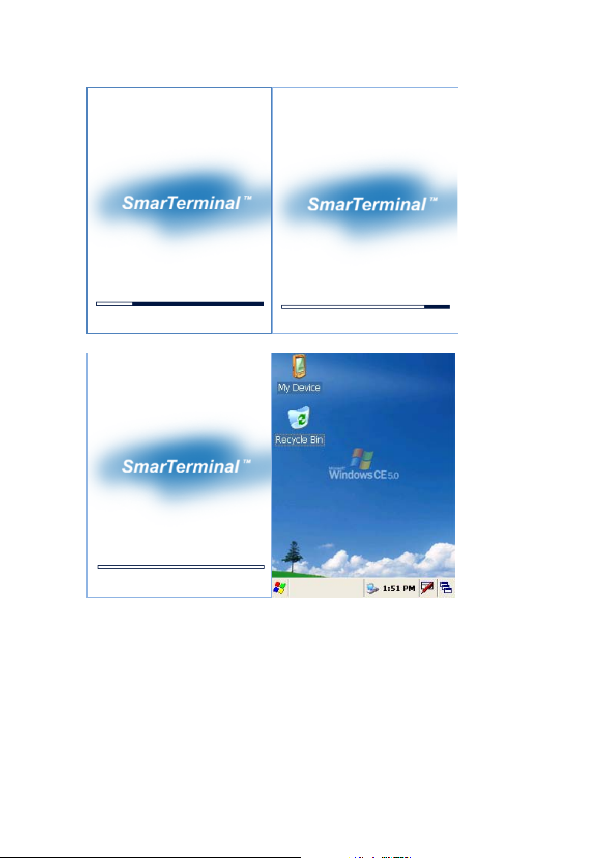
Ver . SP0.03 Ver . SP0.03
Ver . SP0.03
Page 19 6/24/2010
Page 20

5.3 Difference between cold and warm reset
Topic Warm reset Cold reset
Reason for reset If application hangs If operating system locks up and
warm reset does not work
Refresh status It closes all applications
Preserves file system
Procedure to
reset
After state Splash screen will appear shortly
Priority Always try warm reset first Only if warm reset fails then try cold
One touch of software reset button One touch of software reset button
Desktop will appear
It closes all applications
Refreshes RAM
Clears Files too
(Cold reset Version OS)
After Splash screen booting image will
appear and then Desktop screen will be
shown.
Custom setting will remain persistent
reset
Chapter 6 Configuring SmartPay Plus
6.1 Main Display screen description
Following is the display screen picture
Page 20 6/24/2010
Page 21

Task bar
Start button Keyboard icon
It has the following
1 Task bar
2 Start button
1 Task bar: The task bar at the bottom of the screen displays the start menu icon, icons for the active
programs, the current time and system icons for utilities loaded in memory.
It has keyboard icon, which opens and hides the soft input panel (SIP).
It has a button which shows present power status of SmartPay Plus i.e. either AC (power cord) while
charging, backup battery in low power conditions.
Task bar allows user to open and close the programs or utilities.
2 Start button:
Start button is at the left corner in the task bar which allows opening start menu.
Start menu has the following options
Programs > shows all the installed program list as well as user can run the programs from sub-menus
Favorites > User can set the internet favorites and the necessary programs
Documents > list of latest open documents
Settings > Control Panel
Network and Dial-up connections
Taskbar and start Menu
Help > Win CE help manual
Page 21 6/24/2010
Page 22

Run command > To run programs directly
Soft Input panel (SIP)
The keyboard button allows user to open or close the onscreen keyboard. The keys of a keyboard can be
used by tapping them using stylus pen.
6.2 Calibrating the touch screen
In order to use stylus pen on touch screen it is necessary to calibrate the screen first
It can be done in following ways
Start > settings > control panel > stylus icon > Double tap / calibration
Double tap – Use the grid to set the double tap sensitivity for speed and physical distance between the
taps.
Calibrate - Hit the recalibrate button and touch the points shown on the screen till it says calibration over.
Page 22 6/24/2010
Page 23

6.3 Setting up WLAN card
In order to set WLAN settings
1 Open wireless settings screen using Function + home key, same key combination can be used again to
exit the wireless LAN.
2 Select the network which need to be accessed and tap the connect button.
3 To add a new network, double tab on Add new and select the network from the list.
4 confirm it using <Ok> or press <Enter> key on keyboard.
To change the settings of wireless LAN
Start > Settings > Network and Dial-up Connections, Right mouse click and select properties on Wireless
network
Page 23 6/24/2010
Page 24

For IP address
Obtain an IP address via DHCP (Dynamic host configuration protocol) > to get automatic IP address, if this
fails
Specify an IP address > Enter IP address and Server address and select <OK>, it connects to the network.
User can use any browser to access internet.
6.4 Volume / sound control
In Function mode Right and left navigation keys can be used to use to increase and decrease the soun d.
User can check the sound intensity with the background sound which is generated while increasing and
decreasing the volume through application
Start > settings > control Panel > Volume/sound
Page 24 6/24/2010
Page 25

Volume - Adjust the volume as per the requirement using slider and check boxes.
Sound - Select sounds as per the requirement for each event.
Page 25 6/24/2010
Page 26

6.5 Date/Time settings
In order to set date and time do the following
Method 1
Start > settings > control panel > Date and time > Date and time properties dialog will show up.
Method 2
Double tap on the time on the task bar which will open up Date/time properties screen.
Change Date and time as per the requirement.
Page 26 6/24/2010
Page 27

Chapter 7. Applications and operations
7.1. Scanning Barcode (1D/2D CCD type scanner )
CCD Charge coupled device technology scanner consists of a series of light-sensitive circuits that capture
the reflected light and register its intensity and color after it is reflected from a seri es of mirrors. It utilizes
the same technology that video cameras use.
Following procedure is used to read barcodes
1 Execute the application for bar code reading
Start > Programs > Scanning > ScanDemo application or use the icon on desktop
It runs in the background, user can find out by the bar code icon in system tray
2 Aim the scanner window at the barcode
3 Press Left or right barcode scan button for 5 seconds
4 Aim the laser beam at the center of the barcode
5 check the scanning result either with beep sound or scanner LED indicator
Red > Error
Green > success
If there is an error, repeat t he procedure till the barcode gets successfully read
Correct scanning method Wrong scanning method
Page 27 6/24/2010
Page 28

7.2 1D/2D Scanner configuration settings
Select Start > Programs > Control panel > Scanner configuration icon
Before you begin
This Application consists of the following 5 Tabs.
1. Basic -- Changes the default settings of Barcode scanner.
2. Symbologies -- Select the types of Symbologies.
3. Detail -- Changes barcode symbology parameter settings in SmartPay Plus.
4. Options -- Set the other functions of the scanner like Sound and Scan Key change.
5. About -- Shows the scanner configuration version and scanner firmware version.
Page 28 6/24/2010
Page 29

Menu option Function
Trigger time out Scanning time in seconds, which is the waiting time to read a barcode
exactly.
Keyboard Emulation
(Disabled)
There will be no keyboard event after scanning barcode, scanned data
will be transferred directly to the user application
Type writing Shows encrypted barcode as alphanumeric form Keyboard Emulation
(Enabled)
Copy / paste copy /paste the scanned barcode in editor window
Terminator Add a automatic text after each bar code , it can be set as None, CRLF,
CR, LF, Space, T ab, STX-ETX
Continuous Scan
No continuous scanning
(Disabled)
Continuous Scan
Scan continuously the barcode with set time interval.
(Enabled)
Prefix Add code before each barcode e.g. when scanned value is 12345 and
prefix is ABC, It will be sho wn a s ABC12345.
Suffix Add code after each bar code e.g. when scanned value is 12345 and
suffix is ABC, It has shown as 12345ABC.
Check mark means select the barcode type for scanning, the unmarked ba rcodes will not be scanned.
Page 29 6/24/2010
Page 30

Barcode type
Detail setting values for
particular barcode type
Maximum and minimum
length of the barcode
belonging to this
barcode type
Page 30 6/24/2010
Page 31

Scanner configuration version
Scanner firmware version
Restore back the factory scanner’s configurations
Menu Option Function
Sound To activate beep sound
Setting Good Read Tap on this button allows to select the (*.wav) sound file for
beep “On success of barcode scanning”
The selected file name will be displayed in the fill-in above
Setting No Good Read Tap on this button allows to select the (*.wav) sound file for
beep “On failure of barcode scanning”
The selected file name will be displayed in the fill-in above
Default Will restore back the default sound files for both operations
success and failure
Vibrate Select to use vibrate mode on scanning (success/failure)
Vibrate (mille second base) Time interval for vibration
Setting Vibrate time To save the assigned time interval and test it
Default To restore back the default vibration settings
Page 31 6/24/2010
Page 32

7.3 Demonstration program for 1D / 2D Scanner
To start the demonstration program Start > Programs > Scanner > ScanDemo
Startup screen for 1D Sc anner
Select it for Auto-scan
Select it for beep
Select it for Vibration
Scan type will appear
Scan value will appear
To start scanning
Startup screen for 2D Sc anner – Scanner waiting screen
Page 32 6/24/2010
Page 33

Scan type will appear
Scan value will appear
To start scanning Select it for beep
Select it for Vibration
For Scanning bar code user can either press SCAN START button once or one of the hardware buttons on
the left/right side of the SmartPay Plus unit. The result will be same for both procedures.
After successful barcode
scanning the scan type and
value will be displayed in
respective fill-ins
On failure of barcode scanning
Scan fail and try again messages
will appear
For Beep select Beep checkbox, the specific beep sound can be selected through control panel settings.
For Vibration on success or failure select vibrate checkbox.
For Auto scan select the auto scan check box. Unless deselected the auto-scan mode will be activated
whenever user starts the program.
Page 33 6/24/2010
Page 34

In auto scan mode, once the < Scan start > button is pressed, the scanning beam will contin uously come
till <Scan stop> button is pressed.
Start > Program > Run wordpad Scan start > Scanned barcode data will get copied to
wordpad
Page 34 6/24/2010
Page 35

7.4 Printer demonstration program
1. Double click msrprt_test.exe.
2. Initial Screen
Page 35 6/24/2010
Page 36

3. Enter card number.
4. Enter Valid period of the card.
Page 36 6/24/2010
Page 37

5. Enter amount to pay.
The last two digits are Cent unit and decimal point is omitted.
Above is 34 dollars and 56 cents.
6. When clicking non-entering block, keyboard will disappear.
Page 37 6/24/2010
Page 38
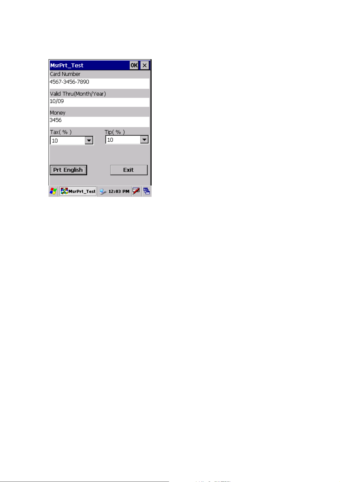
7. Click ‘Prt English’ button to print.
8. Click ‘Exit’ button to close program.
Page 38 6/24/2010
Page 39

7.5 RFID demonstration program
Run RFDDemo Program
1. Start-> Programs-> RFID_M4_Beta0-> RFDDemo Click
2. If the problem has been failed to run
you will need to check the device
properly and try again.
2. If the program runs properly you will
see the Main Screen of the program as
below.
Page 39 6/24/2010
Page 40

Version information
If you’d like to see version information of the program please follow as below.
Click Help-> Click ModuleInfo Tab.. You are able to see Demo version and
Module information.
<Firmware TABLE>
FirmwareVersion <0101060F>
Support for a variety of ISO15693 compliant tags (NXP I-Code SLI SL2 ICS20, TI Tag It HFI
Plus, Pro and Standard, Tagsys C370, ST Micro LRI512, LRI2K, LRIS2K) SkyeTek Secure
Memory Features (AES128, 192 and 256 for Encryption, SHA256 and SHA1 for Hashing)
FirmwareVersion <0103060C>
Payment Continuous Scan Mode (polls for payment cards an reports back Track1 and Track2
data) Supports contactless payments from Mastercard (Magstripe Protocol v3.1),
Visa(Magstripe Protocol v1.4.2), American Express(Application Protocol v1.7), and Discover
(Contactless Payment Protocol v1.01).
FirmwareVersion the ord ers.
Support for a variety of 14443A and B proximity tags suited for access control (NXP Mifare
Ultralight, NXP Mifare Classic, NXP DESFire, ST Micro SRIX4K, ST Micro SRI512)
Page 40 6/24/2010
Page 41

Main Screen
Main Screen configuration
(
You can see the Tag value after reading
in the boxes
You can see History of read tags on this
field..
To clear history
To return to main screen when windows
of
open
To open tagInfo window
To open TagDetail window
Select Tag
Select Tag
①
②
Page 41 6/24/2010
Page 42

To read TagID, click the button
You are able to see and select tag data from the field
TagInfo (EAS/AFI/DSFID)
Click TagInfo .
Detail
Displays Tag information which is being read currently.
You can identify value of EAS/ AFI/ DSFID by clicking Get button of each line.
You can set value of EAS/ AFI/ DSFID by clicking Set button of each line.
Click TagDetail TagDetail window will open if the device
reads Tag..
Page 42 6/24/2010
Page 43

ReadTagAll commend is automatically executed when TagDetail runs.
To read whole memory of the tag
To read data of address number which indicated on .
Reading address 0 is default if there’s no selection
Read data is indicated on
To write data to address number which indicated on
Refer to data on( digit numbers should be same as once read
(To lock data not to be written on TagBlock.
(You can see lock status of data on each address.
ReadTagAll
To read whole memory of the Tag
[ReadTagAll] TagDetail Click If success data comes on the list box..
Page 43 6/24/2010
Page 44

(
(
Page 44 6/24/2010
Page 45

OneReadTag
To check one memory of the address from the tag
[OneRead] Enter address number and
click Read button.
You’ll see the selected data on the box.
Or select it from ListBox.
Page 45 6/24/2010
Page 46

WriteTag
To write data on wanted memory of the address
Click Write button after enter wanted address n umber and data.
Success message appears and the list refreshes when writing succeed.
Fail message appears when data has been When there’s no tag to write.
Page 46 6/24/2010
Page 47

locked or failed during the writing process.
LockTag
To lock data on wanted memory of the address in order to protect the data
Page 47 6/24/2010
Page 48

Click Lock button after entering address number or clicking chosen one from the listbox.
Success message appears and Lock status changes when Locking process succeed.
In case of no tag.
Page 48 6/24/2010
Page 49

7.6 Finger Print
Program execution : Character Screen > AE2510_Demo
Page 49 6/24/2010
Page 50

1. Single
1
○
1) Selects single mode.
2) To read the fingerprint in the fingerprint recognition sensor.
3)Image Capture Successful.
4) The imageTap from will be able to confirm.
2. Continuous
Page 50 6/24/2010
Page 51

1
○
2
○
3
○
4
○
1)Press the “Continuous button”
2) you can see waiting signal(②)
3)next, image capture successufully.
4) waiting..next capture
3. Enroll / Identify
Page 51 6/24/2010
Page 52

User enroll Finger Print and identify.
Page 52 6/24/2010
Page 53

7.7 Camera
1.Exeute
Program execution: Character screen \ Cam_Demo
2. Preview
. Presses Power buttons from the first screen and with like the second time picture sees in advance, is
executed
. Flash buttons will press and is a possibility flash the reverse sides On/Off.
. Shot buttons after taking the screen of present time, store in the folder which is designated
3. Album
Page 53 6/24/2010
Page 54

The third picture will be able to select the format which sees from the album. The second time picture the
fact that shows the image and three re-pictures are the screen which list shows the name of file especially
from the format which sees.
4. Camera Option
The second time picture when pressing Option, is the initial screen. Will select Save Directory and will be
able to select the location which will be stored. The location which is set a default is [within system].
The remaining pictures are the items will be able to set this a white balance/picture size etc.
Page 54 6/24/2010
Page 55

7.8 Operating System upgrade manual
Please follow the steps below to upgrade the operating system on SmartPay Plus.
1 Copy the OS file of “nkupd.bin" to MICRO SDcard.
2 Insert MICRO SDcard
Page 55 6/24/2010
Page 56

3 . Cold Reset the PDA and then you must press the Power Key for os upgrade over 2 second
4. PDA will automatically search for OS to update in MICRO SDCard or SD Card. If there's OS file to
update, move to (No.6)
5. . Main screen for OS Upgrade.
Page 56 6/24/2010
Page 57

6. Press ”Home key”. Update start & Reads SD Card(scnk.bin)
7. If there were no OS file you can see below screen
8. OS upgrade done
Page 57 6/24/2010
Page 58

9. Remove SD card when update completed.
Execute the HW Reset
Ver. SP0.03
10. Image booting
Ver. SP0.03
Page 58 6/24/2010
Page 59

11. Check the OS version in Control Panel > System
12 double click System to check OS Version
Page 59 6/24/2010
Page 60

Chapter 8. Accessories and peripheral devices
8.1 Using Stylus pen
The stylus on the PDA is same as mouse on a PC.
Usage of stylus
1 Navigate the touch screen display
2 Select characters in soft input panel
3 Select applications from the desktop or system tray
4 Select buttons, tabs, fields and text within applications and editors
8.2 Using CDMA (Code Division Multiple Access) module (Optional)
CDMA1-X1 (class B) can be used with SmartPay Plus through compact flash slot which is available on
rear side.
Page 60 6/24/2010
Page 61

Chapter 9. PC Interface
9.1 Ms ActiveSync Installation
It is possible to connect SmartPay Plus to Host Pc using synchronization cable.
Attach one end of synchronization cable to Sync port which is on bottom side of SmartPay Plus and USB
end to host Pc. It is necessary to install Microsoft ActiveSync program.
Following is a procedure to install Ms ActiveSync program on PC.
Select “Next”
Select “I accept the terms in the license agreement” and then “Next”.
Input Username and Organization name and select “Next”.
Page 61 6/24/2010
Page 62

Detect the directory for installation and select “Next”.
Select “Install”.
Installing
Page 62 6/24/2010
Page 63

Select “Finish” to complete the installation.
Select “Yes” to reboot the Pc.
Page 63 6/24/2010
Page 64

9.2 USB ActiveSync
To operate ActiveSync program in PC
Start > Program > Microsoft ActiveSync
For PC ActiveSync settings File > Connection Settin gs >
Select between USB ActiveSync Connections as per requirement.
In USB ActiveSync connections, check “Allow USB connections” and Select “Ok”.
Allow connections to one of the following,
Page 64 6/24/2010
Page 65

Connecting
As soon as the connection is successful following dialog box will be displayed on host PC. To see the files
on SmartPay Plus , click on explorer .
Page 65 6/24/2010
Page 66

Also there will be status icon in system tray to show the status of connection between SmartPay Plus and
Host PC. User can open ActiveSync program by clicking on the icon.
Connected
Disconnected
Data Transfer
Page 66 6/24/2010
 Loading...