

Page 1

SmartCompact Plus
1D/2D Scanner
Quick Reference Guide
Ver 1.0, June 2010
Page 1 6/22/2010
Page 2

Disclaimer
SmartCompact Plus are registered trademarks of
SmartPayTech INC.
All other brand names, product names, or trademarks belong to their respective
holders.
Head Quarters
SmartPayTech INC.
496 Woncheon-dong, youngtong-gu, Suwon-shi, Kyungki-do, Korea
Tel. 82 -31-211-5596~7 / Fax. 82-31-217-8254
Web. www.sammipaytech.com
Sales Office
1057-3 Namhyun-dong, Goanak-gu, Seoul-shi, Korea
Email. sales@smartpaytech.com
Web. www.sammipaytech.com
Page 2 6/22/2010
Page 3

Table of Contents
Introduction.......................................................................................................................................5
Chapter 1 Get to know more about SmartCompact Plus................................................................... 6
1.1 Make sure you have everything...........................................................................................6
1.2 Appearance............................................................................................................................7
1.2.1 Front side...........................................................................................................................7
1.2.2 Rear side............................................................................................................................8
1.2.3 Top side.............................................................................................................................. 9
1.2.4 Bottom side........................................................................................................................9
1.2.5 Left side............................................................................................................................ 10
1.2.6 Right side.........................................................................................................................10
Chapter 2 Hot Keys...........................................................................................................................11
2.1 Front panel with keys..........................................................................................................11
2.2 Front panel keys description...............................................................................................11
2.3 Rear panel with keys.......................................................................................................... 13
2.4 Rear panel keys description............................................................................................... 13
Chapter 3 Power settings and connections...................................................................................... 14
3.1 Power management........................................................................................................... 14
3.2 Install batteries in SmartCompact Plus..............................................................................14
3.3 Battery charging using power adapter............................................................................... 14
3.4 Backup Battery on/off switch.............................................................................................. 14
3.5 Power settings on WIN CE................................................................................................14
3.6 Turn on SmartCompact Plus.............................................................................................. 16
3.7 Turn off SmartCompact Plus.............................................................................................. 16
Chapter 4 Operation modes............................................................................................................. 17
4.1 Normal mode ..................................................................................................................... 17
4.2 Suspend mode...................................................................................................................17
Chapter 5 Resetting SmartCompact Plus........................................................................................ 18
5.1 Warm Reset....................................................................................................................... 18
5.2 Cold Reset.........................................................................................................................18
5.3 Difference between cold and warm reset .......................................................................... 20
Chapter 6 Configuring SmartCompact Plus..................................................................................... 21
6.1 Main Display screen description........................................................................................ 21
6.2 Calibrating the touch screen.............................................................................................. 22
6.3 Setting up WLAN card ....................................................................................................... 23
6.4 Setting up GPRS/GPS/CDMA/GSM Compact Flash card (OPTION) ............................... 24
6.5 Volume / sound c
ontrol......................................................................................................28
6.6 Date/Time settings............................................................................................................. 29
Chapter 7. Applications and operations...........................................................................................30
Page 3 6/22/2010
Page 4

7.1. Scanning Barcode (1D/2D CCD type scanner )................................................................ 30
7.2 1D/2D Scanner confguation settings ................................................................................... 30
7.3 Demonstration program for 1D / 2D Scanner........................................................................35
7.4 Camera................................................................................................................................... 38
7.4.1 Execute .......................................................................................................................... 38
7.4.2 Preview........................................................................................................................... 38
7.4.3 Album.............................................................................................................................39
7.4.4 Camera Option...............................................................................................................39
7.5 Blueman application program............................................................................................ 40
7.5.1 Bluetooth application status........................................................................................ 41
7.5.2 Bluetooth Manager........................................................................................................... 42
7.5.3 Bluetooth settings............................................................................................................. 57
7.6 Operating System upgrade manual................................................................................... 60
Chapter 8. Accessories and peripheral devices...............................................................................64
8.1 Using Stylus pen................................................................................................................ 65
8.2 Using Compact flash (CF) slot........................................................................................... 65
8.3 Using SD (secure digital) peripherals................................................................................65
8.4 Using CDMA (Code Division Multiple Access) module (Optional).....................................65
8.5 Using IrDA port (Infra Red Data Association) .................................................................... 65
8.6 Using RFID Gun reader (Portable UHF/HF reader for SmartCompact Plus).................... 66
Chapter 9. PC Interface.................................................................................................................... 66
9.1 Ms ActiveSync Installation.................................................................................................66
9.2 USB ActiveSync.................................................................................................................69
Appendix A ....................................................................................................................................... 72
SmartCompact Plus Specification Highlights................................................................................72
Physical and Environmental Characteristics.............................................................................72
Performance Characteristics.....................................................................................................73
Data Capture Characteristics.................................................................................................... 73
Network Characteristics............................................................................................................74
Regulatory Approvals................................................................................................................74
Power Supply............................................................................................................................ 74
Appendix B....................................................................................................................................... 75
Version Table................................................................................................................................ 75
Page 4 6/22/2010
Page 5

Introduction
This quick reference guide allows you to use all the advanced features of SmartCompact Plus effectively.
Please go through it once before using SmartCompact Plus handheld terminal.
FCC Information to User
This equipment has been tested and found to comply with the limits for a Class B dig ital device, pursuant to
Part 15 of the FCC Rules. These limits are designed to provide reasonable protection against harmful
interference in a residential installation. This equipment generates, uses and can radiate radio frequency
energy and, if not installed and used in accordance with the i nstructions, may cause harmful interference to
radio communications. However, there is no guarantee that interference will not occur in a particular
installation. If this equipment does cause harmful interference to radio or television r eception, which can be
determined by turning the equipment off and on, the user is encouraged to try to correct the interferen ce by
one of the following measures:
• Reorient or relocate the receiving antenna.
• Increase the separation between the equipment and receiver.
• Connect the equipment into an outlet on a circuit different from that to which the receiver is con-nected.
• Consult the dealer or an experienced radio/TV technician for help
.
Caution
Modifications not expressly approved by the party responsible for compliance could void the user’s authority to
operate the equipment
.
FCC Compliance Information : This device complies with Part 15 of the FCC Rules. Operation is
subject to the following two conditions: (1) This device may not cause harmful interference, and (2) this device
must accept any interference received, including interference that may cause undesired operation
FCC RF EXPOSURE INFORMATION
Read this information before using your phone
In August 1996 the Federal Communications Commission (FCC) of the United States with its action in Report
and Order FCC 96-326 adopted an updated safety standard for human exposure to radiofrequency (RF)
electromagnetic energy emitted by FCC regulated transmitters. Those guidelines are consistent with the
safety standard previously set by both U.S. and international standards bodies. The design of “SmartCompact
Plus” complies with the FCC guidelines and these international standards. Use only the supplied or an
approved antenna. Unanthorized antennas, modifications, or attachments could impair call quality, damaged
your “SmartCompact Plus”, or result in violation of FCC regulations
.
Body-worn Operation
This device has been tested for body-worn operation and meets FCC RF exposure guidelines. Body-worn
operation is restricted to accessories that maintain a minimum of 1.5cm separation to the body and do not
contain metallic components. Use of any other body-worn accessories may not compliance with FCC RF
exposure guidelines. For more information about RF exposure, please visit the FCC website an www.fcc.gov
Page 5 6/22/2010
Page 6

Chapter 1 Get to know more about SmartCompact Plus
1.1 Make sure you have everything
SmartCompact Plus main unit
Stylus Pen
Standard battery pack (
Power adapter
Power cord
Synchronization cable (USB cable)
Backup battery 110mA Lithium-ion (Embedded)
CF card cover
Optional accessories
Docking station (Desktop and vehicle)
Protective carrying case
UHF or HF RFID Gun reader
Synchronization cable (Serial)
3300/4000mAh Lithium-ion
2200 mAH Li-ion)
Page 6 6/22/2010
Page 7

1.2 Appearance
1.2.1 Front side
Main Battery Charge LED
Features and description
Features Function / Description
Scanner LED indicator
LCD Touch screen
Wireless LAN LED
LCD touch screen
display
It shows the running application and desktop,
Stylus can be used to select the application and inputting data on
touch screen
Page 7 6/22/2010
Page 8

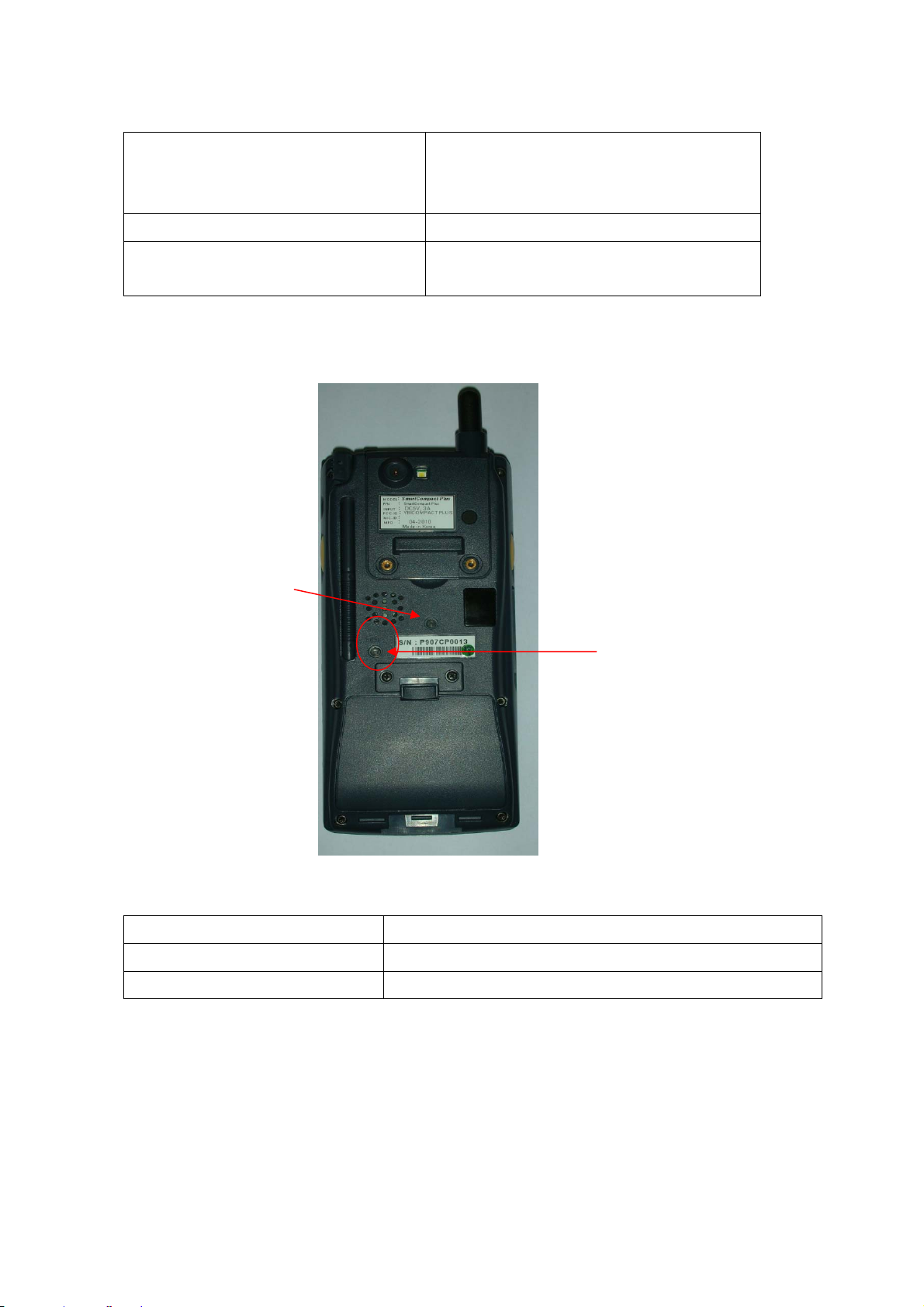
1.2.2 Rear side
p
Antenna
Camera
Stylus pen
Internal s
eaker
Rear panel features
Name Function
Flash LED
Product label
IrDA Sensor
Battery lock switch
Main battery
Stylus pen To use for touch screen
Internal speaker To output audio signals
Hand strap To hold SmartCompact Plus unit
Main Battery To give Dc power to SmartCompact Plus
Battery lock switch To lock/unlock battery pack
Backup battery on/off switch To turn backup battery on/off
Detachable hand strap end To detach hand strap easily for battery change
IrDA Sensor To communicate with other devices using infrared light
Camera To Camera lens
Product label To display model name and serial number
Page 8 6/22/2010
Page 9

1.2.3 Top side
Slot cover
CF slot
Scanner window
Features and description
Features Function / Description
1D Scanner window While scanning the scanner beam is emitted and absorbed
through this window
Slot cover To protect the slot from dust
CF slot To host CF peripherals
1.2.4 Bottom side
Features and description
Features Function / Description
DC input jack For DC power adapter connection to charge the batteries
I/O port To connect to other devices using synchronization cable
I/O port DC I/p Jack
Page 9 6/22/2010
Page 10

1.2.5 Left side
Left Scan Key
SD slot with cover
Features and description
Features Function / Description
Left Scan key To scan the barcode user should press this key also known
was hardware scan key.
SD slot To host SD peripherals
1.2.6 Right side
Audio I/O port
Fnc Side key
Features and description
Features Function / Description
Right Scan key To scan the barcode user should press this key also known
was hardware scan key.
Audio I/O port To connect headset with microphone for audio signals in / out
Page 10 6/22/2010
Page 11

Chapter 2 Hot Keys
2.1 Front panel with keys
Power button
Esc Key
Tab Key
Alpha Key
Function Key
Home key
Navigation key
Alpha-Numeric keys
Enter key
2.2 Front panel keys description
Key name Functions description
Navigation keys Default -- To move the cursor left, right, up and down
In Function mode
<up> To increase intensity of backlight
<down> To reduce intensity of backlight
<right> To increase speaker sound
<left> To decrease speaker sound
Power key (Orange) To turn SmartCompact Plus (sleep / awake) and LCD backlight on/off
ESC key Functions same as “Esc” key on keyboard in windows mode.
TAB key Functions same as “Tab” key on keyboard in windows mode
In function mode used to open application 1 or defined application
Alpha key (Yellow) To switch to alphabet mode
Function key (Blue) Other keys in combination with “Func” key have secondary functions
Enter key Functions same as “Enter” key on keyboard in windows mode.
In function mode works as stylus calibration.
Alpha-Numeric keys To print various characters (0 – 9, a – z etc) in editor window
Home key To clear desktop
In function mode to turn wireless on/off.
Page 11 6/22/2010
Page 12

Alpha-numeric Keys functions in different modes
Key In numeric mode In function mode In alpha mode
<1> Prints number 1 on editor screen Functions as “Ctrl” key on
keyboard
<2> Prints number 2 on editor screen Functions as “Alt” key on
keyboard
<3> Prints number 3 on editor screen Functions as “Del“ key on
keyboard
<4> Prints number 4 on editor screen To open application 2 or
defined application
<5> Prints number 5 on editor screen To open application 3 or
defined application
<6> Prints number 6 on editor screen To open application 4 or
defined application
<7> Prints number 7 on editor screen Functions as “+” key on
To switch to Caps lock
mode
To print a/ b/c on
editor screen
To print d/e/f on editor
screen
To print g/h/i on editor
screen
To print j/k/l on editor
screen
To print m/n/o on
editor screen
To print p/q/r/s on
keyboard
<8> Prints number 8 on editor screen Functions as “-“ key on
keyboard
<9> Prints number 9 on editor screen Functions as “Insert“ key on
keyboard
<0> Prints number 0 on editor screen Functions as “/“ key on
keyboard
<.> Prints number decimal/period on
editor screen
Functions as “*“ key on
keyboard
editor screen
To print t/u/v on editor
screen
To print w/x/y/z on
editor screen
To print blank space
on editor screen
To print ,/:/@ on editor
screen
LED colors and description
Name On state
Page 12 6/22/2010
Page 13
Battery charging LED (Left)
Blinking blue – Low battery (below 10%)
Green – Fully charged
Red – While charging
Wireless LAN indicator LED (Right)
Scanner LED (Top)
2.3 Rear panel with keys
Pistol key
Blinking green - Wireless LAN on
Red - Scanner result (error)
Green - Scanner result (success)
Reset key
2.4 Rear panel keys description
Name Function
Reset key To perform warm and cold reset
Pistol key For bar code reading when pistol trigger is pressed
Page 13 6/22/2010
Page 14

Chapter 3 Power settings and connections
3.1 Pow er management
SmartCompact Plus works on DC power.
A standard lithium ion battery pack (3.7V, 2200 mAH) is provided for Dc power input to
SmartCompact Plus. Charging time is 5 hours with 10 operation and 100 standby hours.
Battery low (below 10%) condition is indicated with Blue power LED.
In order to support SmartCompact Plus in low battery state, there is an inbuilt 110 mAH
rechargeable backup battery provided, it has backup time of 2.7 hours without main battery (in
sleep mode).
For charging both main and backup batteries an AC adapter 100-240 V 50/60 Hz and 5 V/ 3A DC
output is provided with power cord.
Note: Never use SmartCompact Plus unit without main battery.
3.2 Install batteries in SmartCompact Plus
Detach the hand strap end on rear side of SmartCompact Plus. Unlock the Battery lock switch.
Slid the battery latch upwards and insert the battery pack given with the correct polarity.
Note: Only use the batteries which are provided for SmartCompact Plus units.
3.3 Battery charging using power adapter
Connect power cord from AC power supply to AC adapter/charger.
Connect Ac adapter to SmartCompact Plus through DC input jack present on bottom side.
While charging power LED will be red, after fully charged it will be green.
Backup battery also gets charged during this time.
Charging time is 5 hours.
3.4 Backup Battery on/off switch
Backup battery on/off switch is provided to turn backup battery on/off. When the SmartCompact-
Plus unit is dispatched from the factory, the switch is turned off for backup battery power saving.
To turn the switch on/off use stylus pen pointed top.
On position – Up
Off position – down
3.5 Power settings on WIN CE
To check the battery stat us
Start > Settings > Control panel > Power > Power properties > battery > power (main battery /
backup battery)
It shows the charged status of both main and back batteries.
Page 14 6/22/2010
Page 15

A wake mode w hile charging
Page 15 6/22/2010
Page 16

Power schemes Device status
3.6 Turn on SmartCompact Plus
Check the backup battery switch position, to turn on SmartCompact Plus unit it has to be up
position.
Use stylus pen to turn it on.
Connect the main battery to SmartCompact Plus main unit. Make sure that battery is fully charged
for 5 hours, before it is used first time.
3.7 Turn off SmartCompact Plus
To power off SmartCompact Plus, hold the power key for 3 seconds, which will put the unit in sleep
mode. LCD backlight can be turned on/off by one touch on/off of the power key.
Page 16 6/22/2010
Page 17

Chapter 4 Operation modes
4.1 Normal mode
In normal mode all functions will be available and SmartCompact Plus will be active.
4.2 Suspend mode
In suspend mode SmartCompact Plus will look, as if it is turned off.
SmartCompact Plus can be put in suspend mode in following ways:
1 Holding down the power key for 3 seconds, when it is on.
2 If main battery fails.
Note : If SmartCompact Plus is not operated for specified period it can be switch to suspend
mode, this time can be set as follows
Start > settings > control panel > power properties > schemes > battery power
SmartCompact Plus can be put back in active mode in following ways:
1 One press of power button, when SmartCompact Plus unit is off.
2 By putting it in powered docking station.
3 By replacing the batteries with charged ones and press power button.
Page 17 6/22/2010
Page 18

Chapter 5 Resetting SmartCompact Plus
Resetting means closing all applications and refreshing RAM (Random Access memory)
This is done in two ways:
5.1 W arm Reset
If handheld hangs in between and stops responding, please perform warm reset.
In order to perform warm reset, press (one touch) software reset button till handheld starts
rebooting. Warm reset restarts the handheld by closing all the running programs. Always try warm
reset first, if handheld do not respond, then try cold reset. The data whi ch is n ot saved will be
deleted and the saved data will remain in the appropriate directory.
5.2 Cold Reset
A cold reset clears the entire conte nts of RAM, including programs and data loaded in the Object
Store (system memory).
The operating system is reloaded and any applications set up for automatic installation are
reinstalled. Cold reset is only recommended when all other procedures fail and SmartCompact –
Plus stops working.
Follow the instructions below for the cold reset
Method 1
Press and hold function key, and then press software reset key simultaneously, till handheld starts
rebooting.
Software reset Key
Page 18 6/22/2010
Page 19

Method 2
1 Release the lower clip of the hand strap.
2 Remove the battery pack.
3 Slid backup battery switch down and then again up to reset backup battery.
4 Reinstall the battery pack.
Following screen shots shows the cold reset functioning.
Ver . SC.0.02 Ver . SC.0.02
Ver . SC.0.02
Page 19 6/22/2010
Page 20

5.3 Difference between cold and warm reset
Topic Warm reset Cold reset
Reason for reset If application hangs If operating system locks up and
warm reset does not work
Refresh status It closes all applications
Preserves file system
Procedure to
reset
After state Splash screen will appear shortly
Priority Always try warm reset first Only if warm reset fails then try cold
One touch of software reset button One touch of software reset button
Desktop will appear
It closes all applications
Refreshes RAM
Clears Files too
(Cold reset Version OS)
After Splash screen booting image will
appear and then Desktop screen will be
shown.
Custom setting will remain persistent
reset
Page 20 6/22/2010
Page 21

Chapter 6 Configuring SmartCompact Plus
6.1 Main Display screen description
Following is the display screen picture
Task bar
Start button Keyboard icon
It has the following
1 Task bar
2 Start button
1 Task bar: The task bar at the bottom of the screen displays the start menu icon, icons for the
active programs, the current time and system icons for utilities loaded in memory.
It has keyboard icon, which opens and hides the soft input panel (SIP).
It has a button which shows present power status of SmartCompact Plus i.e. either AC (power
cord) while charging, backup battery in low power conditions.
Task bar allows user to open and close the programs or utilities.
2 Start button:
Start button is at the left corner in the task bar which allows opening start menu.
Start menu has the following options
Programs > shows all the installed program list as well as user can run the programs from submenus
Favorites > User can set the internet favorites and the necessary programs
Page 21 6/22/2010
Page 22

Documents > list of latest open documents
Settings > Control Panel
Network and Dial-up connections
Taskbar and start Menu
Help > Win CE help manual
Run command > To run programs directly
Soft Input panel (SIP)
The keyboard button allows user to open or close the onscreen keyboard. The keys of a keyboard
can be used by tapping them using stylus pen.
6.2 Calibrating the touch screen
In order to use stylus pen on touch screen it is necessary to calibrate the screen first
It can be done in following ways
Start > settings > control panel > stylus icon > Double tap / calibration
Double tap – Use the grid to set the double tap sensitivity for speed and physical distance between
the taps.
Calibrate - Hit the recalibrate button and touch the points shown on the screen till it says calibration
over. There is one more way to calibrate , press Function + Enter key.
Page 22 6/22/2010
Page 23

6.3 Setting up WLAN card
In order to set WLAN settings
1 Open wireless settings screen using Function + home key, same key combination can be used
again to exit the wireless LAN.
2 Select the network which need to be accessed and tap the connect button.
3 To add a new network, double tab on Add new and select the network from the list.
4 confirm it using <Ok> or press <Enter> key on keyboard.
To change the settings of wireless LAN
Start > Settings > Network and Dial-up Connections, Right mouse click and select properties on
Wireless network
For IP address
Obtain an IP address via DHTP (Dynamic host configuration protocol) > to get automatic IP
Page 23 6/22/2010
Page 24

address, if this fails
Specify an IP address > Enter IP address and Server address and select <OK>, it connects to the
network. User can use any browser to access internet.
6.4 Setting up GPRS/GPS/CDMA/GSM Compact Flash card (OPTION)
Before installing the GPRS card it is necessary to sign up for GPRS data service with local wireless
carrier. Also get a SIM card that plugs into the CF card before installing it in SmartCompact Plus.
Generally common GPRS CF cards are using serial interface so it is not necessary to install any
extra driver since they can use already available PCMCIA driver.
Note: If need to use very unique type GPRS card, please install the driver provided by
manufacturer.
GPRS CF card can communicate immediately after plug in.
Follow the instructions given below for using GPRS CF card.
1) Select Start> Settings > Network and Dial-up Connections >
Make New Connection
2) Click on Make new connection
Type name of the connection and select Dial-Up connection and select Next
Page 24 6/22/2010
Page 25

3) Select Modem type from the list as GPRS_Modem and Select Next
Tap on Configure to change the Port setting, Flow Control and Call Options as follows
Enter Baud Rate – 115200
Flow Control - None
Extra settings -- +cgdcont = 1,"ip",”internet”, "yyyy"
Note: Each company provides the different setting value. You need to check “+cgdcont” value with
the SIM card company.
Page 25 6/22/2010
Page 26

.
4) Enter Country and area code, phone number and Click Finish. The area code is not mandatory.
5) To connect to The GPRS network, double click on the new connection created
Page 26 6/22/2010
Page 27

6) If the SIM card is purchased from other countries, please put the user name, password, and
domain.
7) Change the Dialing properties as per the requirement
Click Edit to Change Dialing patterns e.g. Enter G for all options
8) Af ter successful connections following screen will be displayed.
Page 27 6/22/2010
Page 28

6.5 Volume / sound control
In Function mode Right and left navigation keys can be used to use to increase and decrease the
sound.
User can check the sound intensity with the background sound which is generated while increasing
and decreasing the volume through application
Start > settings > control Panel > Volume/sound
Volume - Adjust the volume as per the requirement using slider and check boxe s.
Sound - Select sounds as per the requirement for each event.
Page 28 6/22/2010
Page 29

6.6 Date/T ime settings
In order to set date and time do the following
Method 1
Start > settings > control panel > Date and time > Date and time properties dialog will show up.
Method 2
Double tap on the time on the task bar which will open up Date/time properties screen.
Change Date and time as per the requirement.
Page 29 6/22/2010
Page 30

Chapter 7. Applications and operations
7.1. Scanning Barcode (1D/2D CCD type scanner )
CCD Charge coupled device technology scanner consists of a series of light-sensitive circuits that
capture the reflected light and register its intensity and color after it is reflected from a series of
mirrors. It utilizes the same technology that video cameras use.
Following procedure is used to read barcodes
1 Execute the application for bar code reading
> ScanDemo application or use the icon on desktop
It runs in the background, user can find out by the bar code icon in system tray
2 Aim the scanner window at the barcode
3 Press Left or right barcode scan button for 5 seconds
4 Aim the laser beam at the center of the barcode
5 check the scanning result either with beep sound or scanner LED indicator
Red > Error
Green > success
If there is an error, repeat the procedure till the barcode gets successfully read
Correct scanning method Wrong scanning method
7.2 1D/2D Scanner confguation settings
>Scanner setting tab
Page 30 6/22/2010
Page 31

Before you begin
This Applicati on consists of the following 5 Tabs.
1. Basic -- Changes the default settings of Barcode scanner.
2. Symbologies -- Select the types of Symbologies.
3. Detail -- Changes barcode symbology parameter settings in SmartCompact Plus.
4. Options -- Set the other functions of the scanner like Sound and Scan Key change.
5. About -- Shows the scanner configuration version and scanner firmware version.
Menu option Function
Page 31 6/22/2010
Page 32

Trigger time out Scanning time in seconds, which is the waiting time to read a barcode
exactly.
Keyboard Emulation
(Disabled)
There will be no keyboard event after scanning barcode, scanned data
will be transferred directly to the user application
Type writing Shows encrypted barcode as alphanumeric form Keyboard Emulation
(Enabled)
Copy / paste copy /paste the scanned barcode in editor windo w
Terminator Add a automatic text after each bar code , it can be set as None, CRLF,
CR, LF, Space, Tab, STX-ETX
Continuous Scan
No continuous scanning
(Disabled)
Continuous Scan
Scan continuously the barcode with set time interval.
(Enabled)
Prefix Add code before each barcode e.g. when scanned value is 12345 and
prefix is ABC, It will be sho wn a s ABC12345.
Suffix Add code after each bar code e.g. when scanned value is 12345 and
suffix is ABC, It has shown as 12345ABC.
Check mark means select the barcode type for scanning, the unmarke d barcodes will not be
scanned.
Page 32 6/22/2010
Page 33

Barcode type
Detail setting values for
particular barcode type
Maximum and minimum
length of the barcode
belonging to this
barcode type
Page 33 6/22/2010
Page 34

Scanner configuration version
Scanner firmware version
Restore back the factory scanner’s configurations
Menu Option Function
Scan key To define a scan trigger key (side scan key , HOME key,
LEFT key, RIGHT key, UP key, DOWN key, ENTER key)
Sound To activate beep sound
Setting Good Read Tap on this button allows to select the (*.wav) sound file for
beep “On success of barcode scanning”
The selected file name will be displayed in the fill-in above
Setting No Good Read Tap on this button allows to select the (*.wav) sound file for
beep “On failure of barcode scanning”
Page 34 6/22/2010
Page 35

The selected file name will be displayed in the fill-in above
Default Will restore back the default sound files for both operations
success and failure
Vibrate Select to use vibrate mode on scanning (success/failure)
Vibrate (mille second base) Time interval for vibration
Setting Vibrate time To save the assigned time interval and test it
Default To restore back the default vibration settings
7.3 Demonstration program for 1D / 2D Scanner
To start the demonstration program Start > Programs > Scanner > ScanDemo
Startup screen for 1D Scanner
Select it for Auto-scan
Select it for beep
Select it for Vibration
Startup screen for 2D Scanner – Scanner waiting screen
Scan type will appear
Scan value will appear
To start scanning
Page 35 6/22/2010
Page 36

Scan type will appear
Scan value will appear
To start scanning Select it for beep
Select it for Vibration
For Scanning bar code user can either press SCAN START button once or one of the hardware
buttons on the left/right side of the SmartCompact Plus unit. The result will be same for both
procedures.
After successful barcode
scanning the scan type and
value will be displayed in
respective fill-ins
On failure of barcode scanning
Scan fail and try again messages
will appear
For Beep select Beep checkbox, the specific beep sound can be selected through control panel
settings.
For Vibration on success or failure select vibrate checkbox.
Page 36 6/22/2010
Page 37
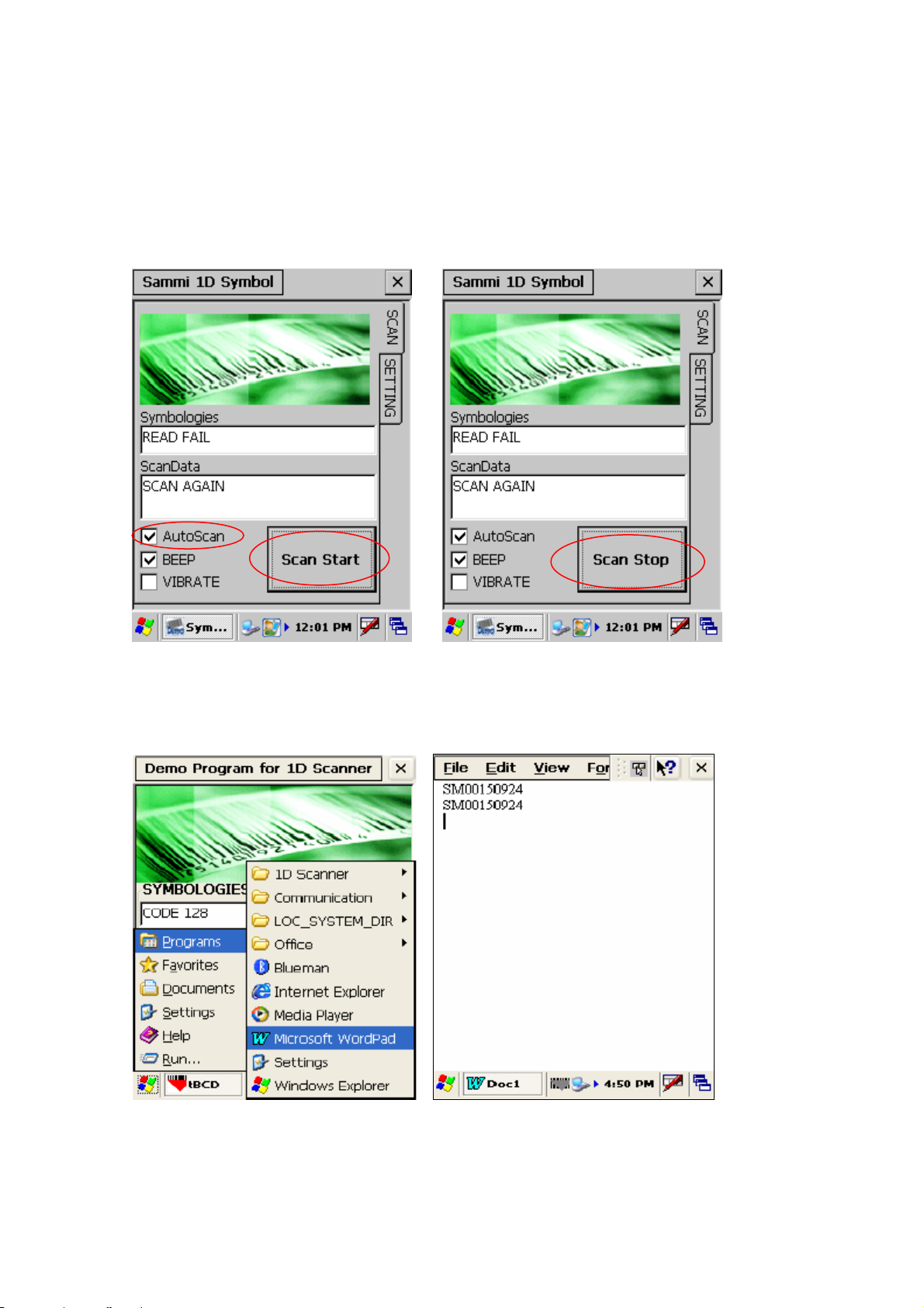
For Auto scan select the a uto scan check box. Unless deselected the auto-scan mode will be
activated whenever user starts the program.
In auto scan mode, once the < Scan start > button is pressed, the scanning beam will continuously
come till <Scan stop> button is pressed.
Start > Program > Run wordpad Scan start > Scanned barcode data will get copied to
wordpad
Page 37 6/22/2010
Page 38

7.4 Camera
7.4.1 Execute
Program execution: Character screen \ Cam_Demo
7.4.2 Preview
. Presses Power buttons from the first screen and with like the second time picture sees in
advance, is executed
. Flash buttons will press and is a possibility flash the reverse sides On/Off.
. Shot buttons after taking the screen of present time, store in the folder which is designated
Page 38 6/22/2010
Page 39

7.4.3 Album
Presses Album and like the second time picture and takes in existing and list of the picture files
which puts to seem
The third picture will be able to select the format which sees from the album. The second time
picture the fact that shows the image and three re-pictures are the screen which list shows the
name of file especially from the format which sees.
7.4.4 Camera Option
The second time picture when pressing Option, is the initial screen. Will select Save Directory and
will be able to select the location which will be stored. The location which is set a default is [within
system].
Page 39 6/22/2010
Page 40

The remaining pictures are the items will be able to set this a white balance/picture size etc.
7.5 Blueman application program
Blueman supports Bluetooth 1/2 and Blueclass 2 (10 mW) specifications.
Note :
Maximum only two services can be connected (SPP and FTP, ActiveSync and FTP)
Page 40 6/22/2010
Page 41

SPP and ActiveSync can not be connected simultaneously since they use the same
outbound port
While both SPP and FTP are in use the service search might not be available.
Whereas the part which is saved automatically in setting is shown in red and others are
saved by closing the setting form.
The class of device of PDA which installs Blueman is applied to Handheld PDA in service
on.
7.5.1 Bluetooth application status
- There are 3 types of Bluetooth status; Off, On, Connection
- You can check the current status of Bluetooth in the tray icon as shown below
User interface Status
Bluetooth Radio Off : Inactive
Gray color
Bluetooth Radio On : Active
Blue color
Bluetooth connection: In use
Green color
Blueman tray icon popup menu
By double clicking on Blueman tray icon user can get popup menu as shown in following
screenshot
Menu name Description
Turn off Bluetooth To activate / deactivate Bluetooth
Can discover me Allow other devices to access PDA using Bluetooth
Bluetooth manager To manage Bluetooth
Page 41 6/22/2010
Page 42

Bluetooth setting To configure Bluetooth settings
Exit To exit Blueman application
7.5.2 Bluetooth Manager
Bluetooth manager is used to manage Bluetooth. It has four menus
Connection, tool, list and view
Connection : Allows PDA to access and connect to other devices which support the same services
e.g. serial, file transfer and AciveSync service.
Menu Function
1 Add serial device with address To add a shortcut to search and connect serial
device using its Bluetooth address
2 Scan for serial devices To search the device with the serial service.
3 Scan for file transfer devices To search the device with file transfer service
4 Scan for ActiveSync devices To search the device with ActiveSync service
5 Scan for all devices To find out all Bluetooth devices
Add serial device with address
This section will enable PDA to search and connect the device with serial service using a specific
address. Follow the steps given to search the Bluetooth device:
Enter Specific address Shortcut icon will appear Double click on icon for popup menu
Page 42 6/22/2010
Page 43

Select “Connect”, the serial service will start with the message “COM8 port was created for SPP
client”.
Double click same icon for the following popup menu.
Disconnect – To stop the service
Delete – To delete the icon
Properties – To show properties of the service
Refresh – To refresh the current con nection or setting information
Scan for serial devices
This is used to create shortcut to find and connect all the devices with serial service.
When Bluetooth address is not known, Scan for s erial dev ices option can be used to search
serial devices.
System will automatically Ser vice query screen Query is finished and serial service
Page 43 6/22/2010
Page 44

Search Bluetooth devices list is displayed as follows
with serial service.
Select specific service & Double click for popup menu
Select <Create shortcut> Select <Connect >
Select “Connect”, the serial service will start with the message “COM8 port was created for SPP
client”.
Double click same icon for the following popup menu.
Page 44 6/22/2010
Page 45

Disconnect – To stop the service
Delete – To delete the icon
Properties – To show properties of the service
Refresh – To refresh the current connection or setting information
Scan for file transfer devices
Use this section to enable your unit to receive files from another Bluetooth device, or from any
device that supports this function (FTP).
Search Bluetooth device: The system automatically searches for a list of Bluetooth devices in the
screen that will support a FTP service.
<Device searching screen> < Service query Screen > < List complete Screen >
Select device & click create Double click on device icon For security authentification
Page 45 6/22/2010
Page 46

Shortcut to get popup menu, select Enter PIN of the device
Connect
To go to the upper folder (You cannot
go from default folder to the upper
folder to prohibit from deleting the
system folder.)
- To Make a new folder
- To Send or receive file
(You cannot download a folder)
- To delete a file
(You cannot delete a folder)
- Refresh
Large Icons : The icons in the current
screen are seen large
Small Icons : The icons in the current
screen are seen small
Page 46 6/22/2010
Page 47

To send a file from remote device to local device
- Click the Local Machine tab, which is defined as the
default.
- Select the file and then click transfer icon. When the
message of “send to remote” pops up. Click “yes”.
Status message “Sending file to remote” is displayed
during file transfer.
When file transfer is done, you can see the message
of “sending file to remote was successful” on the
status bar, located at the bottom of the screen.
Page 47 6/22/2010
Page 48

To send a file from Remote device to Local device
- Click the Remote Machine tab.
- Select the file and click “send to.. icon”. When the
message of “send to remote” pops up. Click “yes”.
- The message of “sending file to local” is shown in the
status bar of screen.
- When the file transfer is done, you can see the
message of “sending file to remote was successful” on
the status bar, located at the bottom of the screen.
Page 48 6/22/2010
Page 49

To close FTP Program
- Tap the close icon(X) in the top-right corner to exit
and disconnect the service connection.
< file transfer service Function>
** Regarding FTP Host function, enter the agreed pin number for both PDA and
other Bluetooth device to make a connection.
Scan for ActiveSync devices
- This section describes how to make a shortcut to search and connect all Bluetooth devices
with ActiveSync service.
Search Bluetooth devices which support ActiveSync service
<Device searching screen> < Service query Screen > < List complete Screen >
Page 49 6/22/2010
Page 50

Select device & click create Double click on device icon Message after successful
Shortcut to get popup menu, select connection
Connect
To disconnect the service
Scan for all devices
This section describes to search and query all Bluetooth devices respective services. User can
make a connection if required.
All Bluetooth devices
When you select this function, you can search and list up all Bluetooth devices with the following
procedure.
Page 50 6/22/2010
Page 51

To search Bluetooth devices
The service type to scan is shown in
the title bar
The status of blueman manager is
displayed in the status bar below.
List of devices which support Press and hold your stylus in the device
Bluetooth service icon for a pop-up menu, then select “Service Query”
Once the service query is To create shortcut, hold stylus Use popup menu to connect
Complete, list of services on service icon to display popup and disconnect the service
which device supports will be menu and select Create shortcut
displayed as follows
Page 51 6/22/2010
Page 52

Tool
This tab enables the device to set the paired statu s with other devi c e or activate/deactivate the
Bluetooth radio.
To save the settings which
were used to connect to
other specific devices
To turn Bluetooth service
on and off alternatively
Setting for paired devices: Follow the steps below to add paired devices
Select Add to scan the Wait till the list is complete On specific device popup menu select
Device to be paired Add paired device to select the device
Enter the PIN
Enter the promised authenticated key in both your device and the relevant device to complete the
connection.
Page 52 6/22/2010
Page 53

Add: To scan the device to connect
Remove: To remove the paired
device
Close: To exit
Double-click a device to see a pop-up menu containing a list of actions you can perform like
below.
Add Paired Device : to make the device paired.
Properties : to see the information on the device.
Refresh : to renew the window(N/A)③
Page 53 6/22/2010
Page 54

Turn on/off Bluetooth
Properties : to see the information on
the device.
This function allows the radio service of the device to turn on or off.
List
This tab enables user to check the scanned device / service, or shortcuts which have been
created earlier options.
Page 54 6/22/2010
Page 55

Shor tcuts: to list up the shortcuts to
connect to the device service, which have
been created in “Connection”
Devices: to list up the devices which have
been scanned in “Scan for all devices”
Services: to show the device services
which the service query has been done in
“Scan for all devices”
Refresh: to renew the current page.
Shortcuts
This function shows the shortcut list of device services, which has been created in.
<Connection>. This is available only after you create the shortcut in a connection tab. If not, the
message of “?“ will appear.
Screen Pop-up Menu Action & Description
Con nect : to connect to the
service
Delete : to delete the shortcut
Properties : to show the device
information
Refresh : to renew the current
window
Devices
This function enables user to review the information on the device service or the other detailed
information. This is available only after you have searched the devices in a connection tab.
Page 55 6/22/2010
Page 56

Screen Pop-up menu Action & Description
Serv ice Query: to scan the
service of the device.
Serv ice V iew: to show the
service , which was saved.
Delete: to delete the device.
Properties: to see the
information of the device.
Refresh: to renew the device.
ervices
This function enables user to view the device service which has a step of service query in “Scan for
all devices”
User can create a shortcut of scanned service.
Screen Pop-up menu Action & Description
Create Shortcut : to make
a Shortcut
Ref resh: to scan the
device again.
Page 56 6/22/2010
Page 57

View
- This tab enables user to control the shortcut display of either large icons or small icons.
Large Icons: The shortcut icons in the current page become large.
Small Icons: The shortcut icons in the current page become small.
7.5.3 Bluetooth settings
This has four submenus General, Accessibility, Services, and About
General
1) Bluetooth status
- To turn Bluetooth radio on / off
(This is same as on/off in a tray icon or Bluetooth manager)
2) Device Identification
A. Name: To change the device name
B. Address: To show the BT address of the device. The
device must be on.
3) Device Scan Length
- To control the device (or device name) scanning time.
Accessibility
Page 57 6/22/2010
Page 58

1) Blueman setting manager
A. Load setting: To load the saved blueman registration value.
B. Save setting: To save the current blueman registration value
2) Startup List
A. Shortcut List: To establish the shortcut list as a default screen
in opening the program.
B. Device List: To establish the device list as a default screen in
opening the program
3) Accessibility
A. Allo w other dev ices to conn ect: To allow the service
query for your device from other devices
B. Other de vices can discov er me : If you don’t check this,
other devices cannot scan your device.
Services
This menu enables you to change the setting values of the Bluetooth service.
Screen Description
1) Serial Port
-To enable or disable SPP Service
(Both Authorization and Authentication are
inactivated because WinCE5.0 doesn’t support
them.)
<<More>> You can check the settings of SPP
Inbound &Outbound Port here. (unchangeable)
Page 58 6/22/2010
Page 59

2) File Transfer Server
- In FTP service, all settings in File Transfer
Server are inactivated because it’s controlled by
OS itself.
<<More>>
(Default folder :My documents\File Transfer)
3) Audio Gateway
- This is supported in MS Stack. However, all
settings are inactivated because the service is
unavailable currently.
(Only possible to scan the service for other BT)
4) Information Exchange
- to switch files of PIM, calendar, and etc.
(Default folder: My documents\Default\Inbox)
Page 59 6/22/2010
Page 60

About
User can view the latest software build version by accessing this tab. Tap ok(x) to exit this
information.
7.6 Operating System upgrade manual
Please follow the steps below to upgrade the operating system on SmartComp act Plus Plus.
1. Copy the OS file of “scnk.bin" to SD card.
2. Cold Reset the PDA and then you must pre s s the Power Key for os upgrade over 2 second.
3. Main screen for OS Upgrade.
Page 60 6/22/2010
Page 61

4. Press Up key. Update start & Reads SD Card(scnk.bin)
5. If there were no OS file you can see below screen
Page 61 6/22/2010
Page 62

6. OS upgrade done.
7. Remove SD card when update completed.
Page 62 6/22/2010
Page 63

Execute the HW Reset
Ver.SC.0.02
8. Image booting
Ver.SC.0.02
9. Check the OS version in Control Panel > System
Page 63 6/22/2010
Page 64

10. you can see the OS Ve rsion.
Chapter 8. Accessories and peripheral devices
Page 64 6/22/2010
Page 65

8.1 Using Stylus pen
The stylus on the PDA is same as mouse on a PC.
Usage of stylus
1 Navigate the touch screen display
2 Select characters in soft input panel
3 Select applications from the desktop or system tray
4 Select buttons, tabs, fields and text within applications and editors
8.2 Using Compact flash (CF) slot
Compact flash slot available on SmartCompact Plus has possibility to insert CF peripherals (50 pin).
The digital platform supports 3.0 V type I/II cards but it can be upgraded to support 3.3 V CF
cards. After inserting the CF card it is possible to close the slot with CF close cover. The cover can
be changed by removing screws located at the top side of SmartCompact Plus as shown in figure
1.2.3 top side using a small Phillips head screwdriver.
To install CF peripherals
Before installation, in order to pull CF cards easily out of a CF card slot, a pull-out
sticker comes with the CF card package. If an equivalent sticker doesn't come with your
card, or your PDA doesn't have an eject button, stick pull-out sticker to pull CF cards e
asily.
In case of closed covers user should remove screws and cover, in sert CF cards, close cover
and fix the screws.
There are different types of CF peripherals available in market which can be con nected to
SmartCompact Plus e.g. CF camera, CF CDMA, CF Bluetooth, CF memory card, GPRS CF
card etc.
For installing drivers for CF peripherals please refer the installation manuals provided with the
equipments.
8.3 Using SD (secure digital) peripherals
On the left side of the SmartCompact Plus SD slot is available for SD peripherals insertion.
For Installation open the cover by removing the screws on the left side of the unit.
Insert the SD card in the slot. System should automatically detect the SD peripheral.
To remove the SD card, press back the card and it will automatically come out.
8.4 Using CDMA (Code Division Multiple Access) module (Optional)
CDMA1-X1 (class B) can be used with SmartCompact Plus through compact flash slot which is
available on rear side.
8.5 Using IrDA port (Infra Red Data Association)
SmartCompact Plus is provided with standard IrDA 1.1 compliant SIR. It can communicate with
another device with IrDA port; the distance in which it can operate is 7.8” – 11.8”. Microsoft
Page 65 6/22/2010
Page 66

ActiveSync is software which can be used for communication.
8.6 Using RFID Gun reader (Portable UHF/HF reader for SmartCompact Plus)
It is possible to connect RFID Gun reader to SmartCompact Plus for UHF and HF tag reading. The
Gun reader can be purchased separately. For more details please refer RFID Gun reader user
manual.
Chapter 9. PC Interface
9.1 Ms ActiveSync Installation
It is possible to connect SmartCompact Plus to Host Pc using synchronization cable.
Attach one end of synchronization cable to Sync port which is on bottom side of SmartCompact
Plus and USB end to host Pc. It is necessary to install Microsoft ActiveSync program.
Following is a procedure to install Ms ActiveSync program on PC.
Select “Next”
Select “I accept the terms in the license agreement” and then “Next”.
Page 66 6/22/2010
Page 67

Input Username and Organization name and select “Next”.
Detect the directory for installation and select “Next”.
Select “Install”.
Page 67 6/22/2010
Page 68
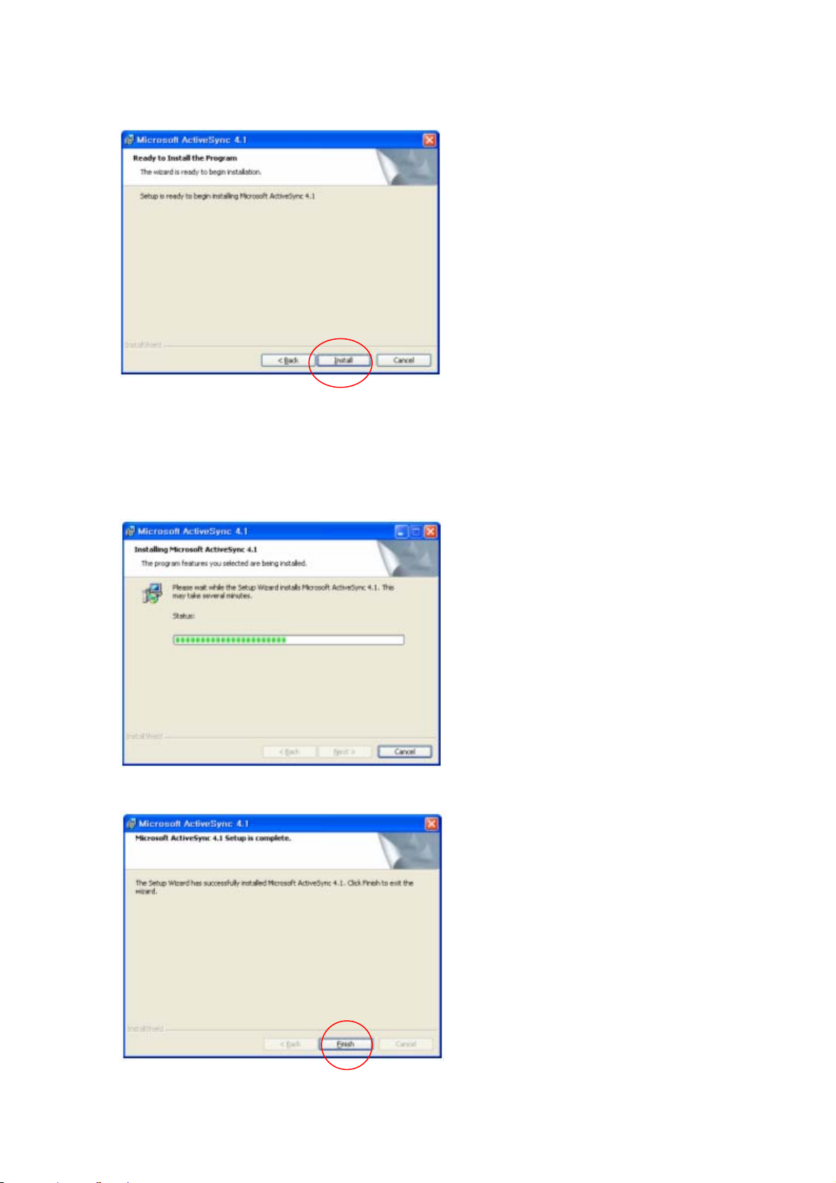
Installing
Select “Finish” to complete the installation.
Page 68 6/22/2010
Page 69

Select “Yes” to reboot the Pc.
9.2 USB ActiveSync
To operate ActiveSync program in PC
Start > Program > Microsoft ActiveSync
For PC ActiveSync settings File > Connection Settings >
Select between USB ActiveSync Connections as per requirement.
In USB ActiveSync connections, check “Allow USB connections” and Select “Ok”.
Page 69 6/22/2010
Page 70

PC Connection has to be
USB for USB ActiveSync Connections.
Connect ActiveSync cable to PDA and PC for USB and Serial connections
Sync cable
Program > Communication > USB ActiveSync
Page 70 6/22/2010
Page 71

Connecting
As soon as the connection is successful following dialog box will be displayed on host PC. To see
the files on SmartCompact Plus , click on explorer .
Page 71 6/22/2010
Page 72

Also there will be status icon in system tray to show the status of connection between
SmartCompact Plus and Host PC. User can open ActiveSync program by clicking on the icon.
Connected
Data Transfer
Disconnected
Appendix A
SmartCompact Plus Specification Highlights
Physical and Environmental Characteristics
Dimensions: 6.6” L x 3.0” W x 1.2 ” D (168 mm L x 78 mm W x 33 mm D), 500 g
Page 72 6/22/2010
Page 73

Display Diagonal: 3.5” (89 mm) diagonal, 2.2” W x 2.9” L (56 mm W x 74 mm L)
Sealing: IP 54
Operating Temperature:
Storage Temperature:
Humidity: 5% - 95% non-condensing
Drop Survival: Withstands multiple 4 ft (1.2 meter) drops to concrete
+14 F to +122 F (-10 C to +50 C)
-4 F to +140 F (-20 C to +60 C)
Performance Characteristics
Processor: 32bit RISC Microprocessor
System Memory: 128 MB SDRAM / 512MB Nand Flash ROM(MAX 1GB)
Display: 240 (W) x 320 (L) (QVGA) transmissive TFT 256K Color LCD, 80 NIT with
resistive touch screen, Sunlight Readable
Keyboard: 16 + 1 alphanumeric keyboard, 2 scanner buttons, navigation, power button,
software reset button
Operating System /
Software
Microsoft® WinCE .NET 5.0, Internet Explorer, InBox, Async, etc., s/w update from
Compact Flash
System Expansion: 1 Compact Flash Type II Slot (external access, supports 3.3V)(OPTION)
1 SD Card Slot (external access)
Application Development Microsoft Embedded Visual C++®, Microsoft Visual Studio .NET®, to build web
services and applications for the Microsoft .NET Compact Framework.
IrDA: Standard IrDA 1.2 compliant SIR Support, in – in (20cm – 30cm) distance
Bar-code Scanning: For SmartCompact Plus-1D -- 1D, CCD type scanner or Laser type Scanner
For SmartCompact Plus-2D – 1D, 2D Imager (CCD type scanner)
LED One triple-color LED for alarm notification / charger indica tor. One duo color LED
for scanner indicator, One duo color LED for wireless
Audio & vibrator One mono speaker and one coin type vibrator
USB Support USB 1.1 Compliant Function(Host & Slave)
Data Capture Characteristics
Light source: 617 nm Highly visible LED
Scan rate Decoded operation 500 scans/s auto-adaptive
Page 73 6/22/2010
Page 74

Un-coded operation 200 operation 200 scans/s
Scan angle
Reading distance Up to 90 cm (35 in)
Ambient light Works in any lighting conditions
Print contrast Down to 25%
Decode software suites
and symbologies
supported
40
For SmartCompact Plus-1D
Codabar, Codablock A & F. Code 11, Code 39, Code 93/93I, Code 128, EAN,
Industrial and Standard 2 of 5, interleaved 2 of 5, ISBT 128, Matrix, MacroPDF
417 (unbuffered mode), MicroPDF417, MSI, PDF417, Plessey, RSS, Telepen,
UCC EAN 128, UPC-A and UPC-E
For SmartCompact Plus-2D
2 Dimensional : PDF417, MicroPDF417, MaxiCode, Data Matrix, QR code, Aztec,
Aztec Mesas, Code 49, EAN-UCC Composite, Snowflake, Dataglyphs
Linear : Code 39, Code 128, Codabar, UPC, EAN, Interleaved 2 of 5, Reduced
space Symbology, Code 93, Codablock F, BC412
Postal : Postnet, Planet code, British Post, Canadian Post, Japanese Post, KIX
(Netherlands) post
OCR Fonts: OCR-A and OCR-B
Network Characteristics
Wireless: 802.11b/g 2.4 GHz
Internal Bluetooth Module (Serial interface) : Class 2
Remote Modem (WAN): GPRS through Compact Flash Slot
GPS: GPS Module through Compact Flash Slot
Regulatory Approvals
FCC ,KCC, CE
Power Supply
Power and Battery
System
2200 mAH Li-ion removable battery (10 operation and 100 standby hours) , 5 hour
recharge time
110 mAh rechargeable built in backup battery, holding system data for 2.7 hours
without main battery
1 DC IN jack, power adapter with 100-240Vac, input and 5V/3A DC output
Power Management: Support for Xscale application modes, including Turbo
Page 74 6/22/2010
Page 75

(Maximum power 400MHz) , Normal, Idle, and Sleep (Less power 200MHz)
Hot swappable battery – Main battery can be changed without switching off the
unit.
Optional : 3000 m AH battery
Appendix B
Version Table
Version: 1 Release Date: 11/30/2006
Page 75 6/22/2010
 Loading...