

Page 1
PRINTER’S INSTRUCTIONS:
INSTR,INSTL,IRC-1 • LINEAR P/N: 223156B • INK: BLACK • MATERIAL: 70 LB. GLOSS WHITE COATED PAPER • SIZE: 11.000” X 8.500” FOLD TO 5.500” X 8.500” • FOLDING: 1 FOLD VERTICAL, FINISH WITH LOGO SHOWING • SCALE: 1-1
223156B • IMAGE 1
LIMITED 5-YEAR WARRANTY
SpeakerCraf t Inc. warrants to t he original retail p urchaser only that th is SpeakerCraft prod uct will be free fr om defects in
materials and workmanship, for a per iod of 5-years, pro vided it was purchase d from a SpeakerCraf t Authorized Dealer.
Defectiv e products must be s hipped, together wit h proof of purchase, prep aid insured to the Speake rCraft Authorize d Dealer
from whom t hey were purchased, or to the SpeakerCraft f actory at the addr ess listed on this ins tallation instruc tion manual.
Freight collec t shipments will be re fused. It is preferab le to ship this product in the original shippi ng container to lessen the
chance of tra nsit damage. In any case, the risk or loss or dama ge in transit is to be bo rne by the purchaser. If u pon exami
-
nation at th e Factory or SpeakerCr aft Authorized De aler it is determined t hat the unit was defe ctive in materials or workman
ship at any ti me during this warra nty period, Speaker Craft or the Speaker Craft Authorized Dealer will, at its option, repair or
replace this p roduct at no addition al charge, except as set for th below. If this model is no longer available and can not be
repaired ef fectively, SpeakerCr aft, at its sole op tion may replace the un it with a current mode l of equal or greater va lue. In
some cases w here a new model is subs tituted, a modificat ion to the mounting su rface may be require d. If mounting sur
face modifica tion is required, Spea kerCraft assumes no responsibility or li ability for such mod ification. All repla ced parts and
product be come the property of SpeakerCraft Inc. Products replaced or repaired under this warranty will be returned to the
original ret ail purchaser, within a re asonable time, freight prepaid.
This warra nty does not include service or part s to repair damage cause d by accident, disaster, misus e, abuse,
negligence, in adequate packing or sh ipping procedures, comm ercial use, voltage inpu ts in excess of the ra ted
maximum of the unit, or serv ice, repair or modificat ion of the product wh ich has not been auth orized or approved by
SpeakerCraf t. This warrant y also excludes normal cosmetic deterioration caused by environment al conditions. This w arranty
will be void if the Serial number o n the product has be en removed, tampered with or defaced.
This warra nty is in lieu of all o ther expressed war ranties. If the pro duct is defective i n materials or workman ship as war
ranted above, the purchaser’s sole rem edy shall be repair o r replacement as provide d above. In no event wi ll SpeakerCraft
be liable for any incidental or conse quential damages ari sing out of the use or i nability to use the
product, e ven if SpeakerCraft I nc. or a SpeakerCraft Inc. Authorized Deal er has been advised of the possibility of such dam
ages, or for a ny claim by any other p arty. Some states do not allow the exclusi on or limitation of consequential damages,
so the above limitation and exclu sion may not apply. All implied warranties on the product are lim ited to the duration of
this expre ssed warranty. Some states do not allow li mitation on the leng th of an implied Warra nty. If the original retail purchaser resides in such a state, this li mitation does not ap ply.
LIT01100 (rev2)
223156B
940 Columbia Avenue, Riverside, CA 92507
•
800-448-0976 • Fax 951-787-8747
www.speakercraft.com
SpeakerCraft
®
SpeakerCraft
®
IRC-1.0 & IRC-1.1
Flush Mount Mini Infrared Receivers
SmartPath
™
INSTALLATION INSTRUCTIONS
The IRC-1.0 and IRC-1.1 are small IR Receivers encased in a threaded tube. They
are designed to mount flush to a cabinet or wall surface with only a circular bezel
exposed to the room. Snap-on Color Cap bezels are included in White, Bone,
Almond, and Black. Also, they can be painted so that a match to any décor is
achievable. Among the unique features of these receivers is an exclusive Ambient
Noise Suppression (ANS) system. It acts to push down IRI, CFL, EMI, or ESI noise
sources so that stronger signals from IR remotes have adequate margin for com
-
mand of the controlled component.
Note: The ANS will take a few seconds to adjust to a given noise source. During
this time, the blue Activity LED will glow brightly and then fade out. If the interfer
ence disappears momentarily, then returns, the fade down process will repeat.
Certain noise sources, however, (such as Plasma Screens) may result in low-level flick
ering even after the fade down. This is normal. Such signals have been acted upon
by the ANS, allowing most equipment to be controlled.
STATUS Brightness
Fig. 3 also shows how an external resistor can be added to reduce the brightness of the
Status LED’s on SpeakerCraft IR Receivers to any desired level.
In this example, a PS-1.0 12V DC Power Supply is used as the voltage source to indicate
ON/OFF status of an A/V Receiver.
Choose a resistor value that achieves the brightness you desire (about 2.2k to 12k, 1/8 W).
Connect it in series with the STATUS lead on each IR receiver desired, as shown.
Fig. 1
Fig. 4
Status LED
(green)
Activity LED
(blue)
STATUS
+12V
GND
IR OUT
4-Conductor
3.5mm Plug
+12V DC
IR OUT
GND
STATUS
IRC-1.0
IRC-1.1
Lens
IR Pickup
Diode
8' Lead
2-5/8" (67mm)
0.47" (12mm)
4-Conductor
Terminal Strip
(included with
IRC-1.1 Only)
Mounting Nut
& Washer (supplied)
Color Cap
(see text)
Front View
0.73" (18.5mm)
Red
Blk
Yel
Wht
FEATURES/SPECIFICATIONS
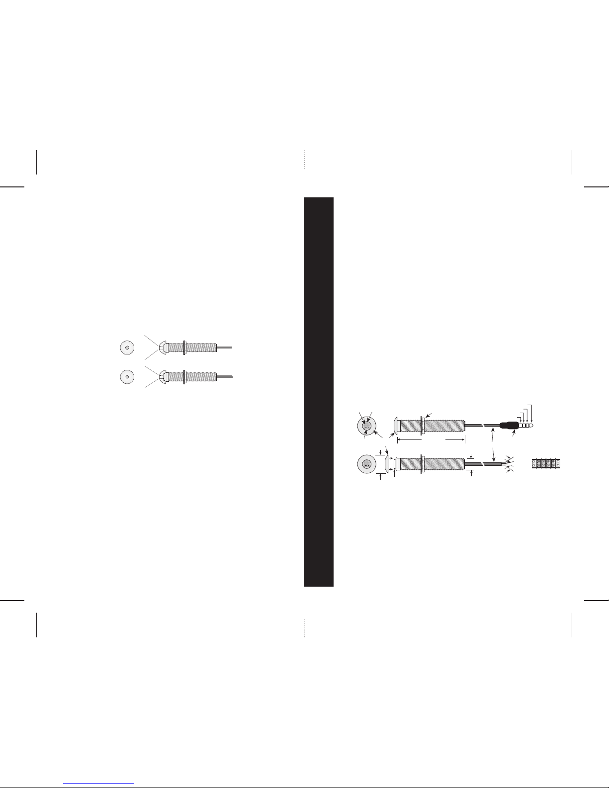
• The IRC-1.0 and IRC-1.1 are identical except for lead termination. (See Fig. 1) The
IRC-1.0 has a unique 3.5mm quad plug to accommodate STATUS as well as IR,
Power and Gnd connections. The IRC-1.1 comes with stripped ends plus a 4conductor terminal strip allowing interface connections to in-wall room-to-room
wiring.
• Exclusive Ambient Noise Suppressor (ANS) system.
• STATUS Indicator: Green LED for System On/Off indication.
• ACTIVITY Indicator: Blue LED indicates IR signal activity in a completed circuit with
a Terminator or an Emitter.
• Requires Power Supply, Terminator Block and Emitters for IR Repeater operation.
PLASMA AMBIENT LIGHT RESTRICTOR CAPS
Included are two special snap-on caps for the restriction of plasma and other types of
ambient IR noise interference. The exclusive Ambient Noise Suppression circuit used in the
IRC-1.0 and IRC-1.1 will handle all types of noise and effectively reduces such noise to an
acceptable level. However, in certain cases, the random strength of the pulsed IR noise from
plasma displays, with scene changes, will cause too much noise to pass to the controlled
component, resulting in intermittent response to IR commands.
If you experience this problem, snap on one of these caps instead of the thinner color caps
supplied. (See Fig. 4) Normally, use the one with the LARGER hole (Cap 1, 3/16"). It will
work in most cases and gives a wider angle of reception (about ± 35˚). If you encounter a
particularly severe case, use the one with the SMALLER hole (Cap 2, 5/32"), bearing in mind
that this narrows the reception angle to about ± 30˚ and reduces the range somewhat.
CAUTION: These caps can be spray painted to match wall colors as with the other color
caps. However, when so doing, you must plug the hole to mask it from the paint. The inside
of the hole must remain black for maximum rejection of the IR plasma interference.
3/16"
± 35˚
± 30˚
Cap 1
Cap 2
5/32"
Front
Side IRC-1.0 or IRC-1.1 IR Receiver
Page 2
PRINTER’S INSTRUCTIONS:
INSTR,INSTL,IRC-1 • LINEAR P/N: 223156B • INK: BLACK • MATERIAL: 70 LB. GLOSS WHITE COATED PAPER • SIZE: 11.000” X 8.500” FOLD TO 5.500” X 8.500” • FOLDING: 1 FOLD VERTICAL, FINISH WITH LOGO SHOWING • SCALE: 1-1
223156B • IMAGE 2
• Power: 12V DC @ 6 mA. Supplied from connected Terminator.
• Crosshatch Shield (internal) inhibits EMI/ESI Interference.
• Carrier Frequency Acceptance Range: 28 to 90 kHz.
• Control Range: Up to 35 feet, depending on remote strength and ambient noise conditions.
• Control Angle: ±50˚ off axis.
• Room-to-Room Wire Recommendations: Use 4-conductor (min.) 24 gauge unshielded
solid or stranded copper wire up to 1200' (Cat. 5e ok), 22 gauge up to 2000', 20 gauge
up to 3000' and 18 gauge up to 5300'.
• Maximum recommended cable length: 5300' with 18 gauge.
• Mounting: Attaches to any flat surface through a
1
⁄2" clearance hole, secured by a nut and
washer (included) on the threaded tube from the backside.
• Color Cap bezels (included) snap on from the front. Provided in White, Bone, Almond,
and Black. In addition, they can be spray painted to match any room color scheme.
• Dimensions: 0.47" (12mm) Dia. x 2
5
⁄8" (67mm) Deep. Color caps are 0.73" (18.5mm) Dia.
SYSTEM CONNECTIONS
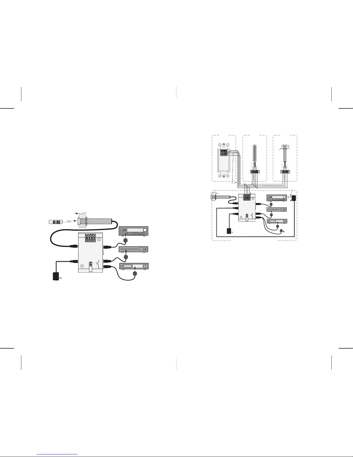
The following are a few typical applications of the IRC-1.0 and IRC-1.1 for IR repeater systems.
A Basic System
Fig. 2 shows a basic plug-and-play installation, such as controlling components that are
behind closed cabinet doors or in a closet.
A Multi-Room System
Fig. 3 is an example of the IRC-1.1 wired IR Receiver in a multi-room system with other
SpeakerCraft IR receivers in various rooms, plus a local IRC-1.0. These control the various
components in the main room or equipment area.
Fig. 2
To 120 V AC
(unswitched)
PS-1.0
Power
Supply
A/V Receiver
Satellite
DVD
AT-1.0
Amplified Terminator
IRC-1.0
Surface Mount IR Receiver
IRE-3.0 Visible Emitter
IRE-3.0
Visible Emitter
IRE-3.0
Visible Emitter
Remote Control
+12V
GND
ST OUT
IR IN
IR
RCVR
STATUS IN
5~24V DC
12V DC
REGULATED
BL ON
BL ON
NET ON
EM ON
EM ON
EMITTERS /
BLASTERS
EMITTERS
NET OFF
AT-1.0
AMPLIFIED
TERMINATOR
SpeakerCraft
Wall Material
®
Fig. 3
IR OUT
ST IN
GND
+12V
IRC-4.0
J-BOX
IR RECEIVER
SpeakerCraft
To 120V AC
(unswitched)
PS-1.0
Power
Supply
A/V Receiver
Satellite
DVD
AT-1.0
Amplified Terminator
IRC-4.0
J-Box IR Receiver
IRC-2.1
Surface Mount IR Receiver
IRC-1.1
Flush Mount IR Receiver
IRC-1.0
Flush Mount
IR Receiver
IRE-1.0
Emitter
IRE-3.0
Visible Emitter
ROOM 1
ROOM 2
ROOM 3
PS-1.0
"STATUS"
Supply
To Switched
AC Outlet on
A/V Receiver
IRE-4.0
Dual
Visible Emitte
r
To Additional
Controlled Unit
CONTROLLED COMPONENTS AREA, MAIN ROOM, ETC.
Rear View
Add Resistor at each IR receiver
to reduce STATUS brightness,
if desired. See text.
Striped
Side
Side
STATUS
+12V
GND
IR OUT
STATUS
(yellow)
+12V
(red)
GND
(black)
IR OUT
(white)
EZ-Connect Terminals
+12V
GND
ST OUT
IR IN
IR
RCVR
STATUS IN
5~24V DC
12V DC
REGULATED
BL ON
BL ON
NET ON
EM ON
EM ON
EMITTERS /
BLASTERS
EMITTERS
NET OFF
AT-1.0
AMPLIFIED
TERMINATOR
SpeakerCraft
Wall Material
Wall Material
®
®
1. Find an inconspicuous recessed cabinet panel or wall surface convenient for mounting
the IRC-1.0. Be sure you have a direct “line-of-sight” path from the user’s remote control
to the IRC-1.0. Drill a
1
⁄2" clearance hole.
2. Pass the lead and the IRC-1.0 through the hole and run the washer and nut up from the
rear for tightening. Refer to Fig. 2
.
3. Prior to tightening the nut, press on the Color Cap of your choice on the front until it
“snaps” into place. Tighten the nut just sufficiently to draw the edge of the color cap
flush with the wall surface. Do not over tighten!
4. Plug the IR Receiver and Emitters into the SpeakerCraft AT-1.0 Amplified Terminator, as
shown.
5. Set the DIP switches on the AT-1.0 to EM ON and NET ON or OFF.
6. Plug in the Power Supply.
7. The remote control, fired at the IRC-1.0, should now control the components.
2
3
1. Pull 4-conductor wire from each room (home runs) to the AT-1.0 Terminator near the
controlled components.
Note: Use 24 gauge unshielded solid or stranded copper wire up to 1200' (Cat. 5e
ok), 22 gauge up to 2000', 20 gauge up to 3000' and 18 gauge up to 5300'. Total
lengths include all wire runs from each room added together, not just the longest
single run. If using shielded wire, these lengths would be reduced by approximately
30%. Also, to achieve operation with long lengths, the lower DIP switch on the
AT-1.0
must be set to the NET ON position.
2. Install the IRC-1.0 and IRC-1.1 in wall or cabinet surfaces per steps 2 and 3 previous.
3. Connect IR receivers in each room to the 4-conductor home runs as shown, using the
4-conductor terminal strip supplied.
4. Connect the home run wires to the correct terminals on the AT-1.0 EZ-Connect Terminals.
Note: You may use the SpeakerCraft CB Connecting Block (not illustrated, stock
# ASM20200) to help connect the many paralleled home run wires to the AT-1.0
EZ-Connect Terminals.
5. Install and plug the various emitters into the AT-1.0.
6. Set the DIP switches to EM ON (or BL ON if using Blasters behind closet doors) and
NET ON.
7. Plug the local IRC-1.0 IR Receiver into the IR RCVR jack.
8. Plug in the PS-1.0 12V DC Power Supply.
9. A remote control, fired at the IR receivers, should now control the components.
Note: Refer to the SpeakerCraft AT-1.0 Instructions for Power Supply considerations.
 Loading...