

Smart Parts shocker 4x4 User Manual

Shocker Sport
TM
Manual
Includes: Shocker Sport 4X4TM and Shocker Sport Turbo
TM
2
WARNING! The Shocker Sport
TM
Paintball Marker is not a toy. Misuse or
careless use may cause serious injury or death. The user and any person within
range must wear eye protection designed for paintball use. Recommended at
least 18 years old to purchase, 14 years old to use with adult supervision, or 10
years old to use on paintball fields meeting ASTM standard F1777-97. Read operation
manual before using. Always use barrel plugs when not involved in actual play. When
gassing and de-gassing the marker’s system, never aim the gun at another person. Always
point the barrel towards the ground. Never use over-filled CO2 bottles as this will “spike” the
system causing the hoses to burst.
Shocker Sport™ Limited Warranty
Smart Parts warrants for 1 year to initial retail purchaser that the Shocker
Sport™ paintball marker and regulator are free from defects in materials and
workmanship. Disposable parts (batteries, o-rings, seals, etc) are not warranted. The
fill poppet and firing piston are warranted for six months. The solenoids and
electronics on your Shocker Sport™ are unconditionally warranted for six months,
plus an additional warranty of six months for electronic parts only (installation and
labor are not included.) This warranty does not cover surface damages (scratches and
nicks,) misuse, or improper disassembly and re-assembly, or attempts made to drill
holes or remove metal from the external surfaces, which could result in degrading the
performance and reducing pressure safety factors. Do not use Teflon tape on any part
of this marker--the tape can break off and plug the solenoids. Instead, use Loctite 271.
Do not make changes to the basic marker parts without written approval. The only
authorized lubricant for the gun is DOW 33 Lubricant. Use of any other lubricant could
result in voiding your warranty. Use only those “on/off” switches purchased from
Smart Parts. Unauthorized “on/off” switches will void this warranty. This warranty is
limited to repair or replacement of defective parts with the customers to pay shipping
costs. This warranty is effective only if the customer returns the warranty registration
card enclosed with the marker.
Thank you for purchasing the Shocker Sport. The Shocker Sport is the culmination of
years of research and testing. Engineers at Smart Parts, building on their experience with
the original Shocker, have given the Shocker Sport a complete overhaul to keep up with the
demands of today’s players and the quality you expect from Smart Parts, Inc. We’ve made
the Shocker Sport smaller, lighter and faster than the original Shocker while keeping the
low pressure, accuracy and extremely low ball breakage! In addition, we’ve upgraded the
electronics, wiring and grounding to make the marker more reliable. The Shocker Sport
now incorporates a digital circuit board, redesigned bolt assembly, new solenoid valves and
an optional integrated air assist port.

THE BASICS
The Shocker Sport 4x4 and Turbo consist of three main assemblies: the Body, the Solenoid
Housing, and the Grip Frame.
Body
The Body is two interlinked systems, the Bolt and the Firing System. It also includes an air
transfer port and air assist fitting port.
The Bolt is contained in the upper chamber and should only be removed when the gun is
degassed. The Bolt is operated by the rearmost solenoid controlling the air going to the front and
rear of the bolt piston in order to make it travel back and forth. The bolt’s function is to load the
paintballs into the breach of the gun and to transfer the air from the firing system to the ball in order
to propel it.
The firing system contains three main moving parts: the firing piston, the fire rod and the fill
poppet. The firing system is controlled by the foremost solenoid valve which when activated starts
the firing cycle. The firing piston and fill poppet are contained in their respective housings. NOTE:
The firing piston also contains a glide ring that is split to facilitate assembly.
The air transfer port distributes air to the entire gun and has 1/8" N.P.T. ports at the front
and rear of the gun. This also contains a gun filter. Clean the filter every six (6) months with
alcohol.
The air assist fitting port is where the 10-32 air fitting is screwed into for the optional air
assist elbow. It is located on the right-hand side of the gun.
Solenoid Housing
The solenoid housing serves three functions. First it encloses and protects the solenoids,
secondly it holds the circuit board and third it connects the body and the grip frame. The solenoid
housing is held to the body using four 10-32 Phillips head cap screws. It is important not to over
tighten these screws as thread damage may occur. The circuit board is mounted to the solenoid
housing using screws and should not be removed or adjusted. The circuit board is coated with a
water-repellent coating to prevent problems in wet playing conditions. The timing of the gun is
preset at the factory.
A small green LED is located on the side of the solenoid housing. This is the battery life
indicator. It will light up continuously when the battery needs replaced. In front of the LED light is
the on/off battery switch. This switch acts as the gun’s safety.
If you have purchased a Shocker Sport Turbo, your solenoid housing will have a 3-way
switch protruding from the front of it. This is the Selective Mode switch. It allows you to select
between Semi-Automatic and Turbo. With the switch in the center position the gun is in Semi-
Automatic mode, the gun shoots once per trigger pull. Moving the switch to the left or right position
when you are facing the back of the gun sets Turbo mode.
Two switch covers are provided with the Shocker Sport , the tournament cover does not
allow the modes to be changed during play. The recreational cap is exposes the switch to allow
changing modes during play.
Grip Frame
The Grip Frame contains the trigger and battery. It is held to the solenoid housing with two
1/4"-20 screws. The front screw can be replaced with a 1/4"-20 stud and a handle. The batteries
are replaceable and can be purchased through Smart Parts or any Smart Parts Authorized
dealers. NOTE: It is highly recommended that you turn off your on/off switch after each day of
play. This will greatly extend the life of the battery—if you do not turn off your battery the power
will slowly drain. With normal care and usage the batteries should last at least 100,000 shots.
There are holes on the bottom of the grip frame for a standard bottomline fitting.

4
General Cleaning and Lubrication
The body of the gun should be cleaned off with a damp cloth. In the unlikely event of a ball
break, the bolt can be removed when the gun is degassed and a squeegee can be run through the
entire upper chamber to clean out the paint residue. DO NOT run the gun under water to clean out
broken paint.
If you should ever lose or damage an o-ring or seal in your Shocker or your Shocker
regulator you may purchase o-ring kits from Smart Parts. They are available in partial and
complete kits for both the Shocker regulator and the Shocker.
Your Shocker will need to be disassembled and re-lubricated with a LIGHT coat of Dow
Corning 33 silicon grease after each day of play! The main parts that need greased are the bolt,
the firing piston and the fill poppet. Proper lubrication is vital to the performance of your
Shocker. If it is not lubricated thoroughly it will not perform at its optimum level! This may
also result in premature failure of the o-rings.
To lubricate the bolt you must unscrew it from the gun. Then using your finger work a small
amount of grease into the holes in the body of the bolt, onto the bolt shaft and on the O-rings
around the outside of the bolt cylinder body. After this is done work the bolt head back and forth to
distribute the grease throughout the assembly.
To lubricate the firing piston (10), first remove the firing cylinder (9) from the gun using a
large flat headed screwdriver. (Note: The firing cylinder is located underneath the barrel on the
front of the gun.) Next using a small pair of needle nosed pliers remove the firing piston from the
firing cylinder. After it is removed spread a light coating of grease on all the o-rings and on the
firing piston guide (11). After this is done replace the firing piston and the firing cylinder.
To lubricate the fill poppet (13) first remove the fill poppet seat (12) from the rear of the gun
using an adjustable wrench. The fill poppet seat is located below the bolt. Once the seat is
removed you must remove the fill poppet guide (14) using a flat bladed screwdriver while holding
the housing with an adjustable wrench. Once the cap is removed you should see the end of the fill
poppet and the fill poppet bearing (19). Remove these items with a pair of needle nosed pliers.
Once you have removed the poppet, spread a light coating of grease on the poppet and the poppet
bearing and reassemble the poppet housing. Finally reinstall the poppet housing into the gun.
Anti-siphon Information
An anti-siphon tube is a tube that is installed in a CO2 tank’s valve in order to help prevent
liquid CO2 from entering the system. The tube is screwed into the back of the valve and bent so
that the end of the tube will be pointing up when the tank is screwed into the gun. When the valve
is completely screwed into the gun mark an “ X” on the outside of the valve (or on the outside of the
tank) near the neck to indicate the up position of the tube inside the tank and to also show that
the tank is an Anti-Siphon Tank. NOTE: Tanks with anti-siphon tubes should only be used on the
cradle or fitting that it was set-up for. If you use an anti-siphon tank on a different bottle adapter,
there is a good possibility that the tube will be oriented incorrectly and draw liquid CO2. Anti-siphon
equipped tanks should never be used on remote systems.
Anti-siphon tubes should only be installed by QUALIFIED AIRSMITHS. Please do not
attempt to install an anti-siphon tube on your tank, have a professional install it for you. If you
need more information regarding this matter please feel free to contact your local paintball field or
Smart Parts at (724) 539-2660.
5
Battery Pack Removal and Replacement
The battery pack is located in the grip frame and can be replaced easily. In order to change
the battery pack one side of the grip must be removed. To do this you must use a Phillips head
screwdriver and remove the two screws in the side of the grip frame holding the grip on. Once this
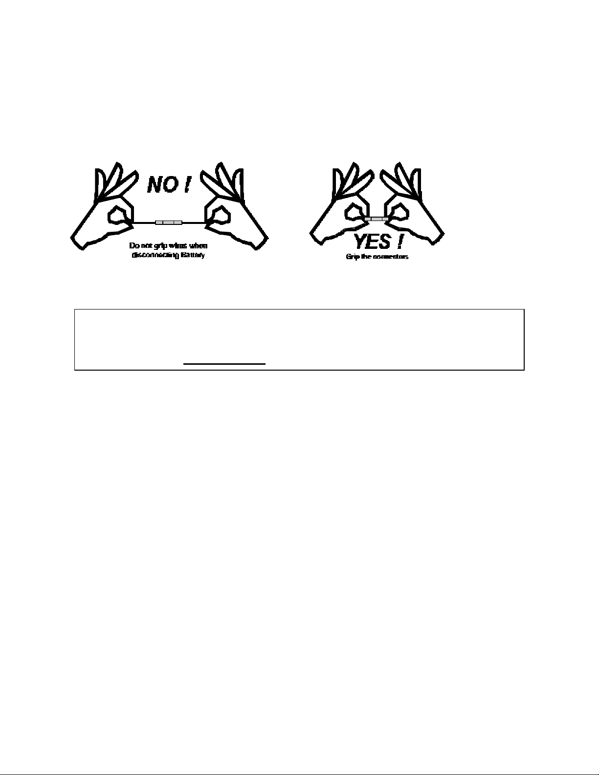
is done you can pull the grip back and see the battery pack. Disconnect the battery pack by simply
unplugging the connector-plug. Note: It is important that the on/off switch be turned off after each
day of play. Replacement battery packs are available through Smart Parts and their distributors.
Disassembly of the Shocker Sport
Before attempting any disassembling of the Shocker Sport : remove all
sources of paint and air, remove the barrel, and disconnect the battery pack.
Failure to follow these precautions may result in damage to the gun and/or
NN grievous injury NN to operator or bystanders.
The disassembly of the Shocker Sport into its three main parts is easy. Usually it is not
necessary to remove the grip frame and the solenoid housing from the body to do normal
maintenance of the components in the body. If you need to access the body or firing chamber skip
down to the second paragraph in this section.
The first step is to remove the grip frame from the solenoid housing. This is done using a
5/32” Allen wrench to loosen and remove the two screws holding the two parts together. If you
have a front handle it takes the place of the front frame screw. Note: Use caution when separating
the grip frame from the solenoid housing. The spring détente in the safety may come out. The
battery pack must also be disconnected from the circuit board. The next step is to separate the
solenoid housing from the main body. The four body screws must be loosened and removed using
a Phillips screwdriver. Once this is done the solenoids must be disconnected from the circuit
board. Disconnecting the solenoids is accomplished by unplugging the connector from the board
itself. Now you have separated the gun into its three main parts.
The body of the gun is the only part that can really be disassembled any further. The first
and easiest part to remove is the bolt. To remove the bolt, simply grasp the knurled end and
unscrew. A schematic of the bolt and its replacement seals is shown on page 13, figure 1.
The next step is to remove all the parts to the firing chamber. The first part of this is the
firing piston housing. This is located beneath the barrel in the front of the gun. The firing piston
housing is removed using a flat head screwdriver, once the threads are out the part can be
removed by simply pulling on it. Note: Once this part is remove the firing rod may fall out of the
gun. Inside the housing is the firing piston. To remove the piston grasp the end of it using a pair
of needle nosed pliers. The firing piston housing is shown on page 13, figure 2.
The poppet housing is the next part that can be remove from the marker body. To remove
this use a 7/8” open-ended wrench and turn counter clockwise. Again once the threads are out the
part can be removed by simply pulling on it. To access the poppet, the poppet guide cap must be
 Loading...