

Smart Parts Impulse 2009 User Manual
SCRN1032X250BS - #10-32 x 1/4" LG
SOLENOID CLAMP SCREW
SCRN0440X0094SCO - #4-40 x 3/32" LG
SOCKET SCREW
ORN0201070BU - O-RING (3x)
IMPULSE
®
Operation and adjustment instructions
ET CUPPED SCREW
IPS136 - SOLENOID
CLAMP PIN
IPS105P - IMPULSE SOLENOID CLAMP
SOL4SHKNRV - SOLENOID VALVE
ORN0401070BU - O-RING (2x)
OIPS143ASM - EXHAUST VALVE
THE IMPULSE® IS DESIGNED FOR USE WITH COMPRESSED
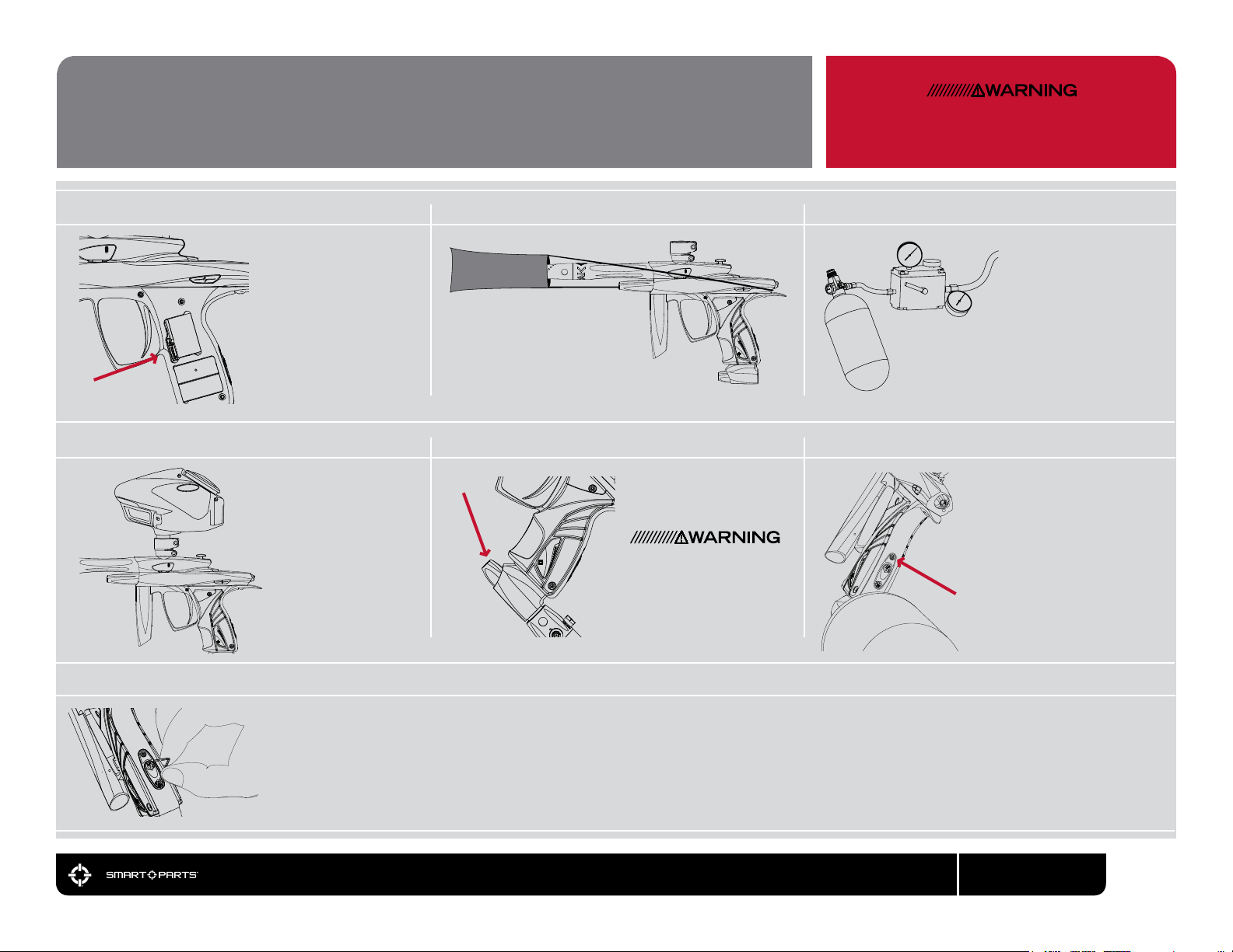
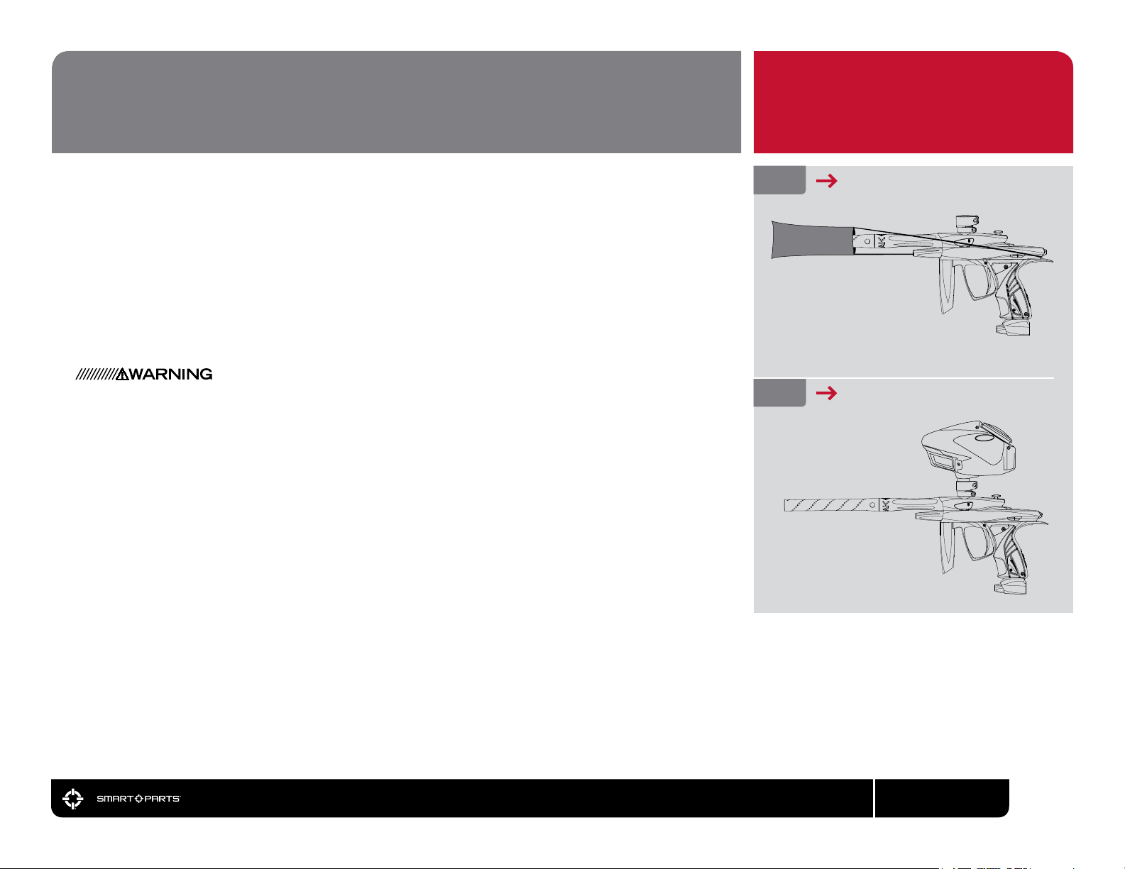
QUICK START
CHARGE BATTERY BARREL BLOCKER FILL TANK
01 02
Make sure that the Impulse®
Lithium-Polymer battery is fully
charged. Use a 5/64-inch allen
wrench to open the left side of
the rubber grip and connect the
®
charger to the charging
Impulse
port before plugging the charger
into a domestic 110 or 240
volt AC electrical outlet (plug
adapters may be needed outside
of US, Canada or Mexico.) The
charger LED will glow green
when charging is complete
(20 to 40 minutes.)
LOADER TURN ON AIR TURN ON IMPULSE®
04 05 06
TM
Unlock the Q-Lock
feedneck and insert your
loader and close the
locking lever. If the locking
lever does not close
easily, do not force it consult the loader section
of this manual.
Due to the high rates of
re that the Impulse
achieve, we recommend
the use of a modern highperformance loader.
®
can
Secure the rubber grip, then
assemble and install the included
barrel into the Impulse
supplied barrel blocker over the end
of the barrel, securing its cord as
far back on the Impulse
possible, and cinching it tight.
®
. Put the
®
body as
®
®
bottom-
by
Gently gas up the Impulse
slowly turning on the air system
or turning the Impulse
line adapter knob clockwise.
A gentle rise in pressure is
important, as a sudden blast
may reduce the service life of
the Impulse
®
’s internals.
AIR (NITROGEN) AND CAN BE DAMAGED BY LIQUID CO2.
03
Have your compressed air
(HPA) tank lled by a person
who is properly trained to do
so. If using an HPA system
with an on/off valve make
sure it is in the OFF position.
If using a screw-in style
preset HPA system like the
Max-FloTM SISTM, ll it while
it is removed from the
marker. See the Gasses
section of this manual for
more information.
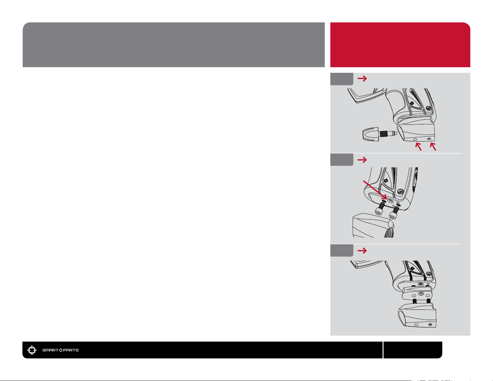
®
Turn on the Impulse
pressing the power button
momentarily. The Impulse
indicate its battery charge level
(see the Battery section for
more information.) and be ready
to re. If you need to disable
®
mode to re gas without
Vision
paint, push the button for
approximately one-half second.
Press and hold the power
button until the Impulse
panel LED goes dark, to turn
the marker off. This acts as an
electronic safety.
by
®
will
®
control
ADJUST VELOCITY
07
Fill the loader with paintballs and turn it on. While wearing ASTM compliant paintball goggles in an area where all bystanders are protected, remove the barrel blocker and re over
a chronograph to measure the velocity. Using a 3/32-inch allen-wrench, adjust the primary regulator through the lower (red) opening in the Impulse control panel on the rear of the
grip frame. Turn counter-clockwise to increase velocity/pressure, and clockwise to decrease. Take three or four shots after every adjustment to allow the gas pressure inside the
marker to stabilize. Adjust until the marker is ring consistently within the limits for the eld where you are playing (for safety reasons, never adjust the Impulse to re at greater than
300 feet per second.) If you are unable to reach the desired velocity, or for more advanved velocity and pressure adjustment instruction, see the pressure balancing section of this
manual. Depending on what modes of re are allowed at the eld where you are playing (semi-automatic, PSP, etc.) you may need to adjust the Impulse
Firing Mode section for more information.
800.922.2147 www.smartparts.com
®
’s Firing Mode. See the
00
TABLE OF CONTENTS
Quick Start
Getting Familiar
Barrel Blocker / Hopper
Gasses and Gas System Mounting
Batteries and Charging
Paint/Velocity/Vision
Pressure Balancing
Electronic Adjustment
Trigger Adjustment
Barrel
Unloading/Degassing
Cleaning - Regular Maintenance
Advanced Maintenance
Troubleshooting
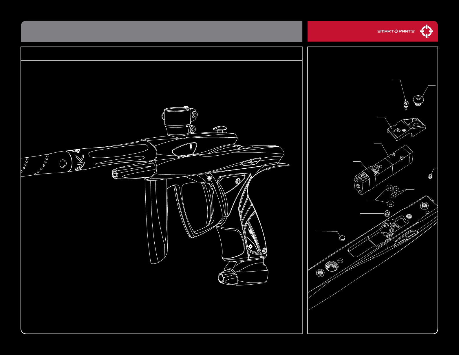
Parts Diagrams
00
02
03
04-06
07-08
09
10
11-15
16
17
18
19-20
21-24
25-26
27-39
– THE IMPULSE® IS NOT A TOY.
– MISUSE OF THE IMPULSE® MAY
RESULT IN SERIOUS INJURY OR DEATH.
– EYE PROTECTION DESIGNED FOR
PAINTBALL USE MUST BE WORN BY
THE USER AND ANY PERSON WITHIN
RANGE OF THE IMPULSE®.
– SMART PARTS® RECOMMENDS THAT
THE IMPULSE® ONLY BE SOLD TO
PERSONS 18 AND OLDER.
– THOROUGHLY READ THE IMPULSE®
OPERATION AND INSTRUCTION
MANUAL BEFORE OPERATING.
800.922.2147 www.smartparts.com
01
GETTING FAMILIAR
PLEASE READ CAREFULLY
STATISTICS
WEIGHT:
OPERATING PRESSURE:
POWER SOURCE:
PROPELLANT:
RATE OF FIRE:
OPERATION:
MODES OF FIRE:
ANTI CHOP SYSTEM:
BARREL THREAD:
LUBRICANT:
2.1 lbs.
260-320 psi propulsion / 50-60 psi pneumatic control
Impulse® Lithium Polymer Rechargeable Battery
Nitrogen/Compressed air
20bps in league modes - Uncapped in semi-automatic
Low pressure electropneumatic
11 Semi-automatic and Enhanced Modes
Break Beam Vision
Smart Parts
®
®
For proper and consistent operation, the Impulse® should
only be lubricated with SL33KTM lubricating grease.
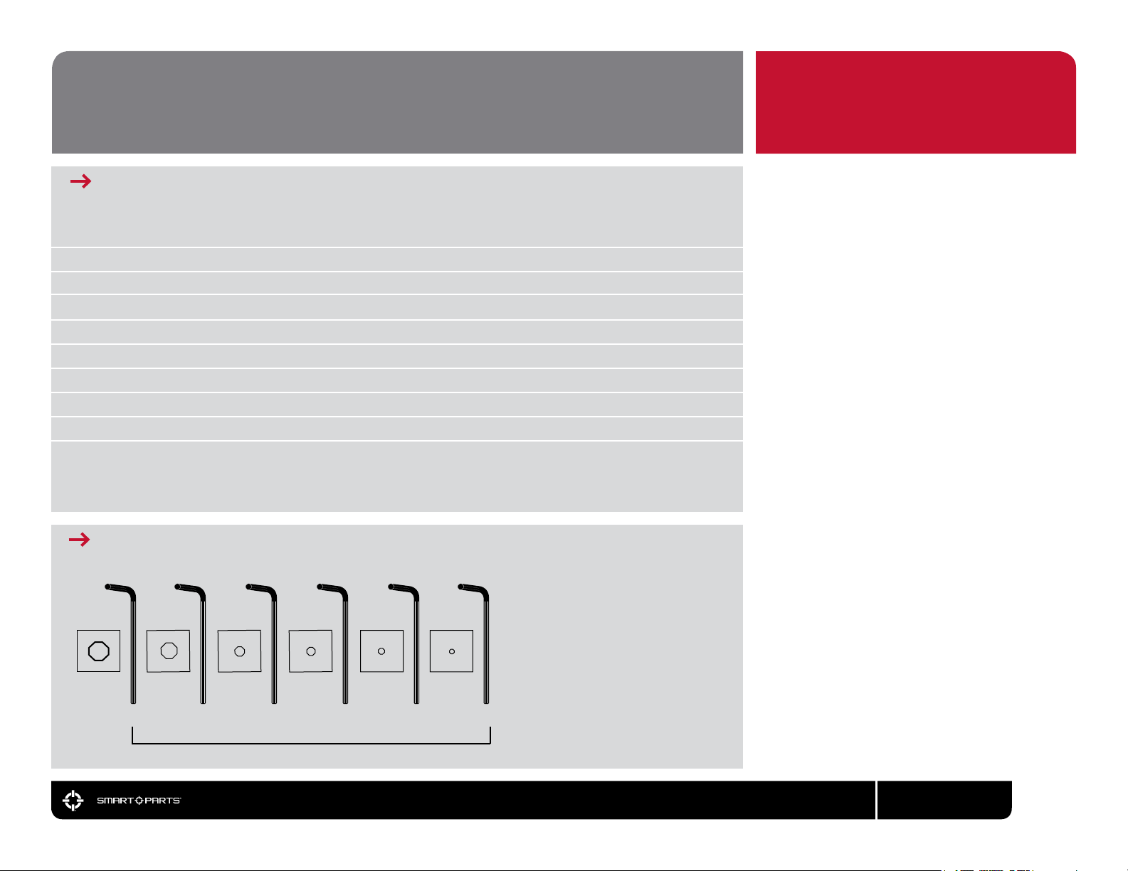
REQUIRED ITEMS FOR MAINTENANCE
3/8” 5/32” 3/16” 3/32” 5/64” 0.050”
3/8” - Relief Valve
5/32” - Foregrip / Q-Lock / ASA
3/16” - Valve Chamber / End Cap
3/32” - Regulator Adjustment
5/64” - Grip Screws
0.050” - Trigger Adjustments
MAINTENANCE
The Impulse® has been designed with
simplicity in mind so that you can
concentrate on your game instead of
your marker. It has a bolt and hinged
eye covers that allow for fast-access
eld-stripping and cleaning. This DOES
NOT mean that you should neglect your
Impulse®. If you take care of it off the
eld, your Impulse® will take care of you
on the eld. For best performance, clean
and grease your Impulse® frequently.
Many players disassemble and clean their
Impulse® after every use. While this may
seem a bit extreme, being vigilant in the
upkeep of your Impulse® will extend its
useful life considerably. Playing in the rain
will not damage your Impulse®, but you
should NEVER immerse it in water. If your
Impulse® should become waterlogged,
remove the barrel and rubber grips
and allow it to dry out, then follow the
disassembly instructions for full cleaning.
Clean out mud and paint with a damp
cloth and alcohol. Grease the Impulse®
ONLY with SL33KTM pneumatic grease.
Use high quality paintballs.
ALLEN WRENCHES
800.922.2147 www.smartparts.com
02
BARREL BLOCKER/HOPPER
PLEASE READ CAREFULLY
BARREL BLOCKER
The Barrel Blocking Device is a critical piece of paintball safety equipment - nearly as important as
paintball goggles. The Barrel Blocker serves to protect against accidental discharge of a paintball by
catching it before it can cause harm. A Barrel Blocker is included with the Impulse® and must be used
every time it is handled in an area where people or property are not properly protected by paintball
goggles or paintball eld netting. To use the Barrel Blocker simply slip it over the end of the barrel and
stretch its cord back over the back of the Impulse® or the rearmost part over which it can be securely
looped. Use the strap’s adjuster to cinch the strap tight, so that the Barrel Blocker can provide
protection against accidental discharge of a paintball.
The Barrel Blocker should only be removed when the Impulse® is on a “live” paintball eld and all
persons involved are wearing proper paintball protection.
HOPPER
The Impulse® is a high performance tournament grade paintball marker. The break-beam Vision
system means that you won’t need to worry about chopping paint because your trigger nger is faster
than your hopper. However, if you want to realize the Impulse®’s maximum repower potential, you
will need to use a high performance loader. High performance loaders, especially those which provide
force-feeding, will yield the best results with the Impulse®.
The Impulse® is equipped with a Q-LockTM locking feedneck that allows it to adapt to the small size
differences in hopper neck sizes, yet lock or release quickly. Flipping the Q-LockTM latch outward
will open the locking mechanism, and folding the latch into its slot, ush against the feedneck will
cause the feedneck to clamp onto a hopper. If the Q-LockTM is not gripping tightly enough, or can
not be easily locked because it is too tight, it may be easily adjusted. Simply ip the Q-LockTM latch
to the open position, and turn the Q-LockTM adjuster clockwise with an allen wrench to tighten the
mechanism, or counter-clockwise to loosen.
FIG. 1
FIG. 2
BARREL BLOCKER IN USE
USE HIGH PERFORMANCE LOADER
800.922.2147 www.smartparts.com
03

GASES
NEVER PUT OIL IN A COMPRESSED AIR REGULATOR OR
TANK - ONLY APPLY MANUFACTURER
RECOMMENDED LUBRICANTS.
GASES
®
The Impulse
approximately 60 psi to operate its valve actuating piston. Because of this low operating pressure and a
built in relief valve, it may safely use CO2 as a power source. The Impulse® is optimized for compressed air,
and best performance will be obtained when using an HPA system.
Whether using compressed air or CO2 it is important that the Impulse® is not exposed to sudden “pops”
of pressure. Always turn off (clockwise) the Impulse® grip-integrated Air System Adapter (ASA) before
screwing in a compressed air system or anti-siphon CO2 tank by turning its knob counter clockwise at
least 3 full turns. When turning the grip-integrated ASA on, do so slowly, so that the gas pressure inside
the marker is raised smoothly. Be gentle to the internals of your Impulse® and they will reward you with a
long service life.
High Pressure Air systems (HPA) are the preferred power source used with the Impulse®, as they are
unaffected by temperature uctuations and do not have the potential for liquid problems. HPA systems
consist of a tank and a regulator, and are typically rated to store air or nitrogen at pressures of 3,000 or
4,500 psi. Although pure nitrogen is almost never used in paintball, many players call compressed air
“nitro” as air is made of more than 70% nitrogen.
The Impulse® is congured for use with screw-in style HPA systems. Although HPA systems pre-set to
deliver approximatly 400 psi (low output) will work with the Impulse®, 800 psi (high output) systems are
preferred, to reduce the risk of gas starvation under rapid re.
Never use oil or any petroleum based cleaner or lubricant in a compressed air regulator or tank.
Exposure to pressurized air increases oil’s ammability and can cause a serious safety hazard. Only use
manufacturer recommended lubricants with compressed air systems, and follow the manufacturer’s
maintenance and operation instructions explicitly.
If you are using your Impulse® with an adjustable output compressed air system, it should be set to
deliver about 800 psi. The Impulse®’s grip-integrated regulator can accommodate a wide range of input
pressures, so exact adjustment of the air system is not critical.
is a low-pressure paintgun. It uses gas pressure of approximately 260 psi to re a paintball,
FIG. 3
HPA TANK BEING FILLED
800.922.2147 www.smartparts.com
04
GASES (CONT.)
PLEASE READ CAREFULLY
GASES (CONTINUED)
While CO2 can be used to power the Impulse®, it not recommended, because its pressure uctuates
with temperature and use. The important thing to remember if using CO2 is that liquid CO2 must not
be delivered to the Impulse®. Although the relief valve integrated into the Impulse® expanded volume
foregrip provides the marker with protection from pressure spikes, those pressure uctuations can
cause poor marker performance. Because liquid CO2 is more dense than CO2 gas, it is easily blocked
through the use of gravity.
Two ways to use CO
Anti-siphon tanks have a J shaped tube professionally installed inside. When the tank is screwed into
a bottom line ASA, like the one that is standard on the Impulse®, with their anti-siphon side up, the
tube delivers gas only. The anti-siphon tube works like a diver’s snorkel, repositioning the gas intake
from the valve to the top side of the tank.
A remote hose allows a standard (non-siphoned) CO2 tank to be carried in a player’s pack. Not only
does this make the total weight of the Impulse® less, but it also allows the tank to be placed vertically,
so that its valve is at the top, while gravity holds the liquid CO2 at the bottom. It is important to note,
that lying down on the eld, or crawling while using a remote can cause liquid CO2 to be fed to the
paintgun as the tank is turned on its side.
with the Impulse
2
®
are an anti-siphon tank or a remote line.
FIG. 4
FIG. 5
COMPRESSED AIR
2 WITH ANTI-SIPHON [CUTAWAY VIEW]
CO
IMPORTANT
CO2 may also be congured with a remote
hose with-out Anti-Siphon. [Not Shown]
800.922.2147 www.smartparts.com
05
GAS SYSTEM MOUNTING
PLEASE READ CAREFULLY
GAS SYSTEM MOUNTING
The Impulse® integrated air system means that there are no hoses or hose ttings anywhere on the
inside or the outside of the marker, instead gas is channeled through passages machined into the
Impulse® body and grip frame, greatly reducing the possibility of leaks.
The Impulse® bottom-line style Air System Adapter (ASA) is mounted to the Impulse® grip frame by a
pair of paintball industry standard inline 10-32 screws.
To remove the bottom-line ASA for cleaning or replacement, unload and degas the Impulse® following
the instructions in this manual. Remove the compressed air system from the ASA, and remove the
ASA control knob by fully unscrewing it from the ASA body.
Using a 5/32-inch allen wrench, access the two screws securing the ASA from underneath the ASA
body (see arrows in Fig. 6.) Once these have been unscrewed, they may be individually slid to the
center of the ASA, and lifted out the top.
Installation is performed in a reverse of the removal process, making certain that the integrated
air o-ring (see arrow in Fig. 7) is properly seated in the bottom of the Impulse® grip frame before
attaching the ASA. Lightly lubricate the ASA control knob o-ring with SL33KTM.
If a slightly lower air system placement is desired, the optional integrated air drop rail may be installed
between the ASA and the grip frame. Both the rail’s integrated air o-ring, as well as that of the grip
frame, must be inspected and the longer ASA screws included with the rail must be used.
FIG. 6
FIG. 7
FIG. 8
REMOVE THE ASA CONTROL KNOB
ASA MOUNT SCREWS
INSTALLING DROP RAIL
800.922.2147 www.smartparts.com
06
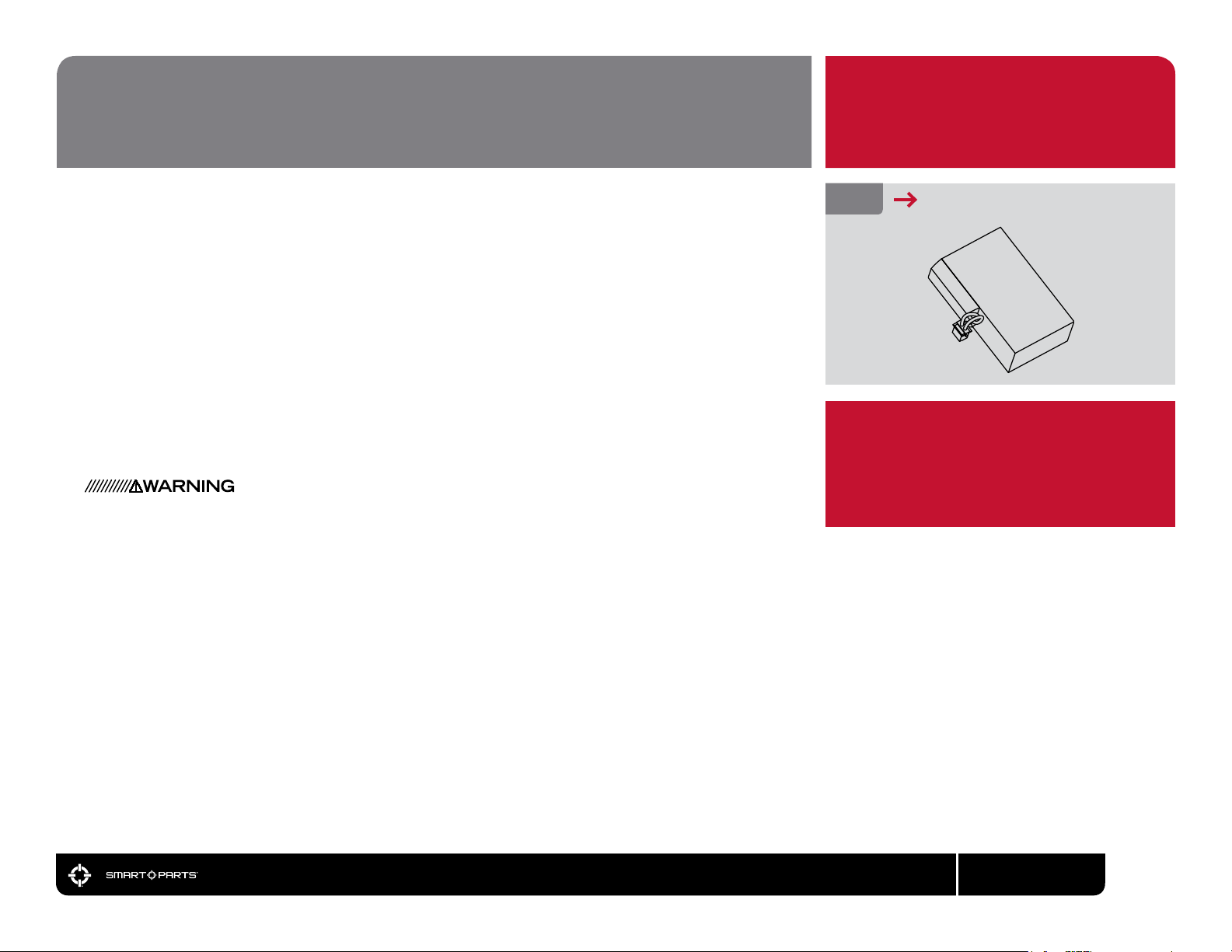
BATTERY SAFETY
PLEASE READ CAREFULLY
BATTERY SAFETY
The Impulse® uses a Lithium Polymer battery as its power source. To ensure a long and safe operational
life, the battery must be handled with care. Do not expose the battery to high temperatures, such as
leaving it out in strong sunlight or an enclosed vehicle in hot weather for a prolonged period of time.
Do not expose the battery to high levels of static electricity, as this may damage its on-board control
circuits. These types of situations may cause damage leading to re or explosion. If the battery leaks,
avoid contact with the uids. In case of eye contact, do not rub. Rinse with clean running water and
seek medical attention immediately or loss of sight may occur. If the battery gives off an odor, generates
heat, becomes discolored/deformed or appears abnormal, remove it from any connected device and
place it in a metal box for immediate disposal.
When traveling, make sure that any spare Impulse® batteries are protected from moisture or physical
damage. Check with your airline and or the Transportation Safety Administration for specic policies
regarding packing and transport of Lithium batteries on passenger aircraft.
DO NOT IMMERSE THE BATTERY IN LIQUID. STORE IN A COOL, DRY ENVIRONMENT WHEN NOT IN
USE. DO NOT REVERSE POSITIVE (+) AND NEGATIVE (-) TERMINALS OR SHORT-CIRCUIT. DO NOT
CONNECT THE BATTERY TO AN ELECTRICAL OUTLET. DO NOT STRIKE OR THROW THE BATTERY
AGAINST A HARD SURFACE. DO NOT MODIFY, PIERCE OR SOLDER NEW CONNECTIONS TO THE
BATTERY. STORE AND TRANSPORT THE BATTERY IN A CASE WHICH PROTECTS IT FROM DAMAGE
OR CONTACT WITH SHARP OR METAL OBJECTS WHEN NOT IN USE.
FIG. 9
IMPORTANT
THE IMPULSE® BATTERY AND CHARGER CONTAIN
BUILT IN OVERCHARGE AND OVER-DISCHARGE
PROTECTION CIRCUITRY, AND ARE NOT
COMPATIBLE WITH OTHER CHARGER OR
MARKER SYSTEMS.
IMPULSE® LI-PO BATTERY
800.922.2147 www.smartparts.com
07
BATTERY CHARGE & SWAP
ONLY USE THE SUPPLIED CHARGER TO CHARGE THE
IMPULSE®. USE OF AN INCORRECT CHARGER TYPE CREATES
A RISK OF FIRE OR EXPLOSION AND INJURY OR DEATH.
CHARGE LEVELS
The Impulse® battery uses Lithium Polymer chemistry, the same type of batteries used to power mobile
phones. In addition to rapid charging capabilities, the LiPO batteries are immune to “battery memory”
effects caused by only draining them part way. When the Impulse® is turned on, the status LED in
the Impulse® control panel at the rear of the grip frame will blink ve times, indicating an estimate of
the battery’s charge level. The blink colors, green, yellow and red will indicate a progressively weaker
battery charge level. Because battery discharge rates vary with load and temperature, it is
best to always make sure the Impulse® is fully charged before a day’s play, rather than rely on the
charge level estimate.
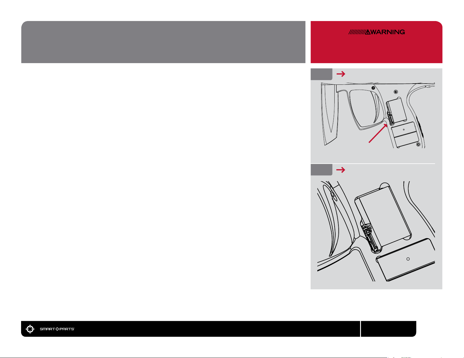
To charge the Impulse®, unload and degas the marker following the instructions in this manual. Use
a 5/64-inch allen wrench to open the left side of the rubber grip and connect the Impulse® charger to
the charging port before plugging the charger into a domestic 110 or 240 volt AC electrical outlet (plug
prong adapters may be needed outside of US, Canada or Mexico). The charger LED will glow red to
indicate that the battery is charging and green when charging is complete. Unplug the charger from
the wall outlet, then from the Impulse®. Close and resecure the grip before use. Mobile charging from a
car’s electrical system may be accomplished by plugging the Impulse® charger into a 120 volt AC power
inverter, or obtaining an optional Smart Parts® Impulse® 12-volt charger.
BATTERY SWAP
Swapping a low battery for a fully charged battery can be used as a rapid alternative to charging when
either the electrical power or time needed to charge is unavailable. To exchange the Impulse® battery,
unload and degas the marker, then open the left side of the grip, the same as when charging. Gently lift
out the battery, taking care not to strain its leads. Unplug the battery from the Impulse® circuit board,
taking care to pull on the connector itself, not the leads. Plug in and install the new battery. The battery
plugs into a small white connector located just above the black charging port. Battery orientation is
important. The battery is not completely rectangular, the bulge in the battery’s edge created by its
internal discharge control circuit board should be oriented to the top and front, above the charging port
in the grip frame. The battery connection is charge-oriented, and designed so that it can not be plugged
in backwards. If the battery connector does not plug in easily, do not force it, try reversing it, make sure
the plug us facing the correct direction. Make sure the battery leads (wires) are tucked neatly into the
grip frame before closing and resecuring the grip. Later, when charging is available, charge the battery in
the marker, then swap batteries again and charge the low battery in the marker.
FIG. 10
FIG. 11
CHARGING PORT
BATTERY ORIENTATION
800.922.2147 www.smartparts.com
08
PAINT/VELOCITY/VISION
NEVER ADJUST THE IMPULSE® TO FIRE ABOVE
300 FEET PER SECOND, AS SERIOUS INJURY
MAY RESULT.
PAINT
Even the best quality paintballs will vary in size from one batch to the next and as weather conditions
change. While your Impulse® will work well even with a poor paint to barrel t, optimal performance will
be achieved with a proper t. Paintgun barrels are available in a variety of bore sizes to allow the user
to select the best possible t. The Impulse® barrel is factory congured with The Freak® bore insert. The
Freak® Kit or Freak JR
TM
kits will provide you with a set of compatible inserts that will allow your Impulse
®
barrel to quickly adapt to paint of different diameters.
The ideal t between the paintball and the barrel is when the ball is inserted in the bore (the end that
screws into the Impulse®) and does not slip or roll through to the muzzle (the business end) on its own.
The ball should sit in place, even when the barrel is pointed straight down. If the paintball can roll out on
its own, the t is too loose. The ball should be able to be expelled from the barrel by blowing it out, like
a blowgun, using a minimal amount of breath. If the ball is difcult to blow through, the t is too tight,
which can lead to ball breakage.
VELOCITY
The velocity, or speed at which the Impulse® res a paintball, must be measured and adjusted to below
the paintball eld’s velocity limit immediately before each day of play (for player safety.) If CO2 is used,
velocity should be checked and adjusted multiple times during the day. In an area where it is safe to re
paintballs, while wearing ASTM compliant eye and face protection for paintball, re three or four shots
over a chronograph to measure the velocity at which the paint is being red.
If velocity adjustment is necessary, use a 3/32-inch allen-wrench to adjust the primary regulator.
Adjustment is made through the center of the circular red arrow on the Impulse® control panel at the
rear of the grip frame. Turn counter-clockwise to increase velocity/pressure, and clockwise to decrease.
Take three or four shots after every adjustment to allow the gas pressure inside the marker to stabilize.
Measure velocity with the chronograph, and continue adjusting until the marker is ring consistently
within the velocity limits for the eld where you are playing. For safety reasons, never adjust the Impulse®
to re at greater than 300 feet per second.
®
VISION
INSTRUCTIONS
When the Impulse® is turned on it will be in Vision® mode. The internal infrared eye will be used to detect
whether or not a paintball is in the breech. This feature practically eliminates the possibility of a chopped
paintball. Vision® mode is indicated by a green glow of the status LED on the Impulse® at the rear of the
grip frame. Vision® mode can be de-activated by pressing the power button for 1/2-second while the
Impulse® is on. Vision® mode off is a red glow of the Impulse® control panel LED. Vision® mode may be
turned back on by once again pressing the power button for 1/2-second.
FIG. 12
INCREASING VELOCITY
800.922.2147 www.smartparts.com
09
PRESSURE BALANCING
BETWEEN THE DWELL TIMING, PRIMARY REGULATOR
AND SECOND-STAGE REGULATOR THE IMPULSE®
OFFERS A WIDE RANGE OF ADJUSTMENT. IF
THESE SETTINGS ARE NOT PROPERLY BALANCED,
PERFORMANCE WILL SUFFER.
PRESSURE BALANCING
The velocity and cyclic rate of the Impulse® depend on the balance of three settings. The dwell
setting affects how long the marker will hold open its solenoid valve to drive the ring piston
towards the pressure balanced poppet valve. The pressure setting of the primary regulator will
determine the pressure of gas released each time the valve opens, and the pressure setting of the
second-stage regulator will determine the pressure of the gas used to drive the ram forward.
The interrelationship of these three adjustments affect how long the poppet valve stays open. This
in turn has a direct effect on the marker’s feel, sound signature and efciency. The Impulse® valve
uses seals that expose both ends of the valve core to the atmosphere in order to balance against
internal gas pressure. It takes very little force to open the valve, regardless of the pressure of the
gas it is controlling. This allows the Impulse® to re reliably with a variety of pressure and volume
combinations while still using a very low pressure on the ring piston, making the marker gentle
with brittle paint and giving it almost no recoil.
For best all-around performance, Smart Parts® recommends the following initial set-up proceedure
for balancing dwell and pressure settings. Further tuning to personal taste may be done from there,
but if the marker becomes unbalanced and performs poorly, performing the pressure balancing
procedure will restore reliable operation.
Set the dwell timing to its default value of 8ms, following the the electronic adjustment section of
this manual.
Using a 3/32-inch allen-wrench through the Impulse® control panel on the rear of the grip frame,
turn the lower adjustment screw (red) all the way in (clockwise) then back out 6 turns. This will
place the primary regulator at its factory default setting.
Next, while wearing paintball goggles, and in a safe area (such as the chrono range at a paintball
eld) turn the the upper (blue) adjustment screw all the way in. Then set the second-stage regulator
by backing the adjuster out while ring over a chronograph until the Impulse® can re consecutive
shots at a consistent velocity. Then set the velocity following the velocity adjustment procedure.
FIG. 13
FIG. 14
ADJUSTING PRIMARY REGULATOR
ADJUSTING SECOND-STAGE REG
Always follow the velocity adjusting procedure after making any pressure adjustments to ensure
that the Impulse® is not red at velocities over 300 feet per second. If, after adjustment, the
Impulse® shows inconsistent velocity, increase the second-stage (upper, blue) regulator by
adjusting counter-clockwise with a 3/32-inch allen wrench.
800.922.2147 www.smartparts.com
10
ELECTRONIC ADJUSTMENT
PLEASE READ CAREFULLY
LOCKING/UNLOCKING
Most paintball tournaments, scenario games and elds have rules which do not allow a player to
make adjustments that can affect velocity (such as dwell) or ring mode during a game. These
rules require that a marker be locked so that such adjustments can not be made without using
tools, which are not allowed on-eld. Although used in all types of paintball, this is commonly
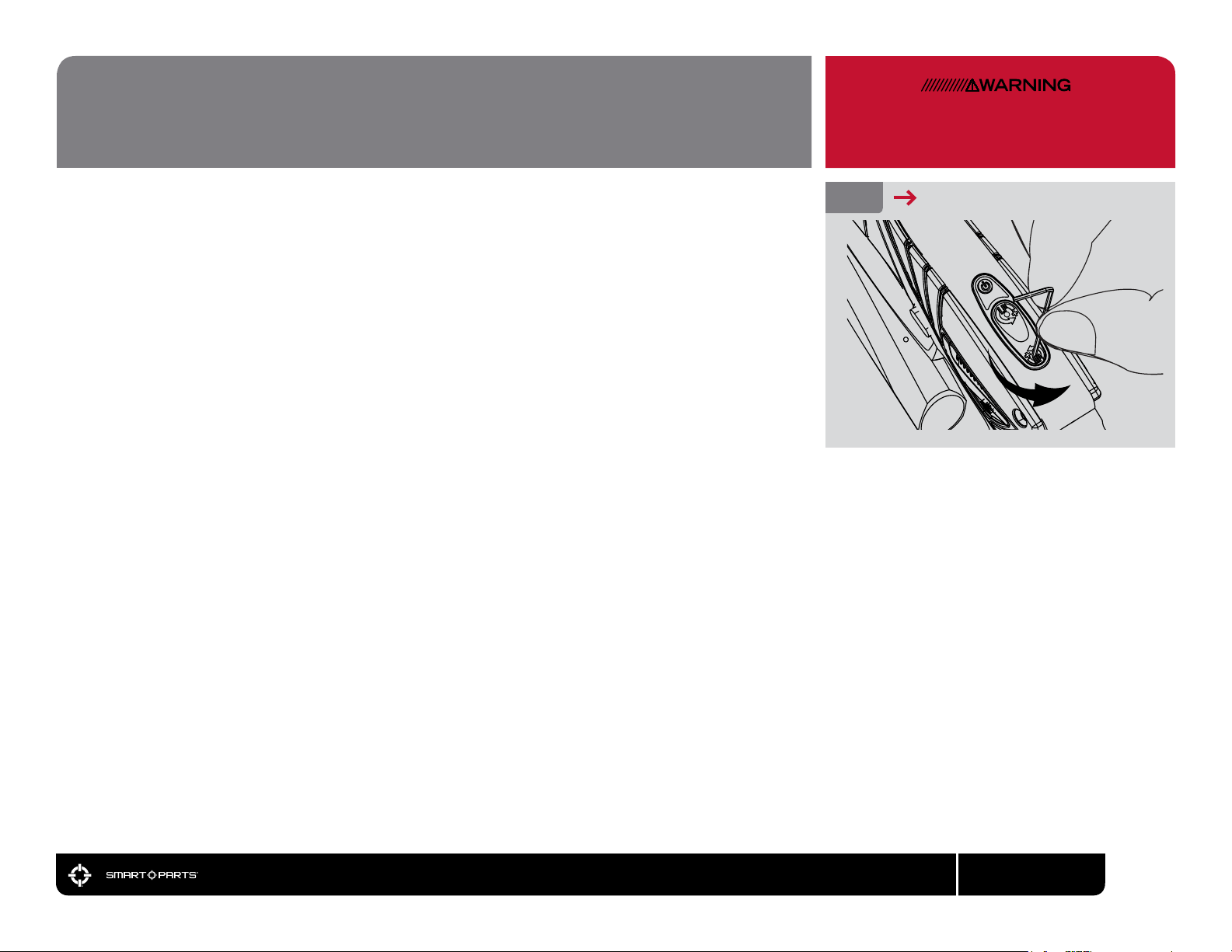
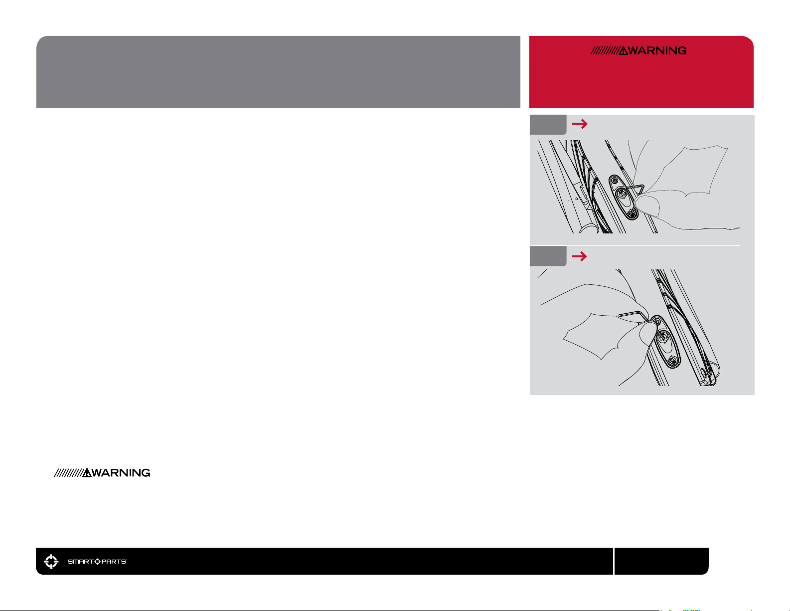
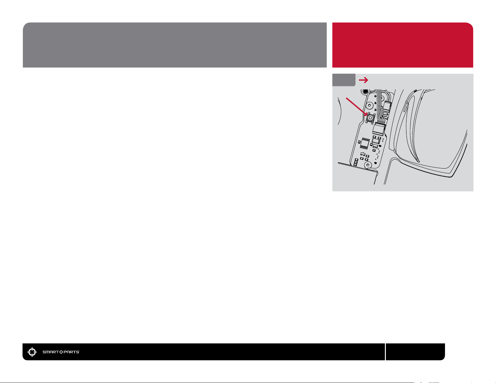
called a tournament lock. To lock or unlock the Impulse® circuit board, unload and degas the
marker following the instructions in this manual, then use a 5/64-inch allen-wrench to open the right
side of the rubber grip. Turn the Impulse® on, then press and hold the tournament lock button for
approximately two seconds. The Impulse® indicator LED will blink twice to indicate the the eld-lock
has been toggled. The LED will blink red to indicate that the marker has been locked, or green to
indicate that it has been unlocked.
ENTERING PROGRAMMING MODE
Enter programming mode, after the marker has been unloaded and degassed, by holding the trigger
back and then pressing the power button to turn the marker on, then releasing the trigger. Once
in programming mode, pull the trigger to cycle through the available parameters. The speed and
color at which the LED on the Impulse® control panel blinks will indicate the selected parameter. If
the marker will not switch into programming mode, the Impulse® is locked, and must be unlocked
before changes can be made.
When the desired parameter is selected, wait approximately three seconds, and the LED will blink
light blue, with the number of blinks corresponding to the parameter’s current value. To enter a
new value, pull and hold the trigger until the LED turns off, then pull the trigger a number of times
corresponding to the desired setting. The LED will blink light blue a number of times to conrm
that a new value has been set. To exit programming mode, press and hold the power button,
turning the marker off.
FIG. 15
TOURNAMENT LOCK
800.922.2147 www.smartparts.com
11
 Loading...