

Page 1
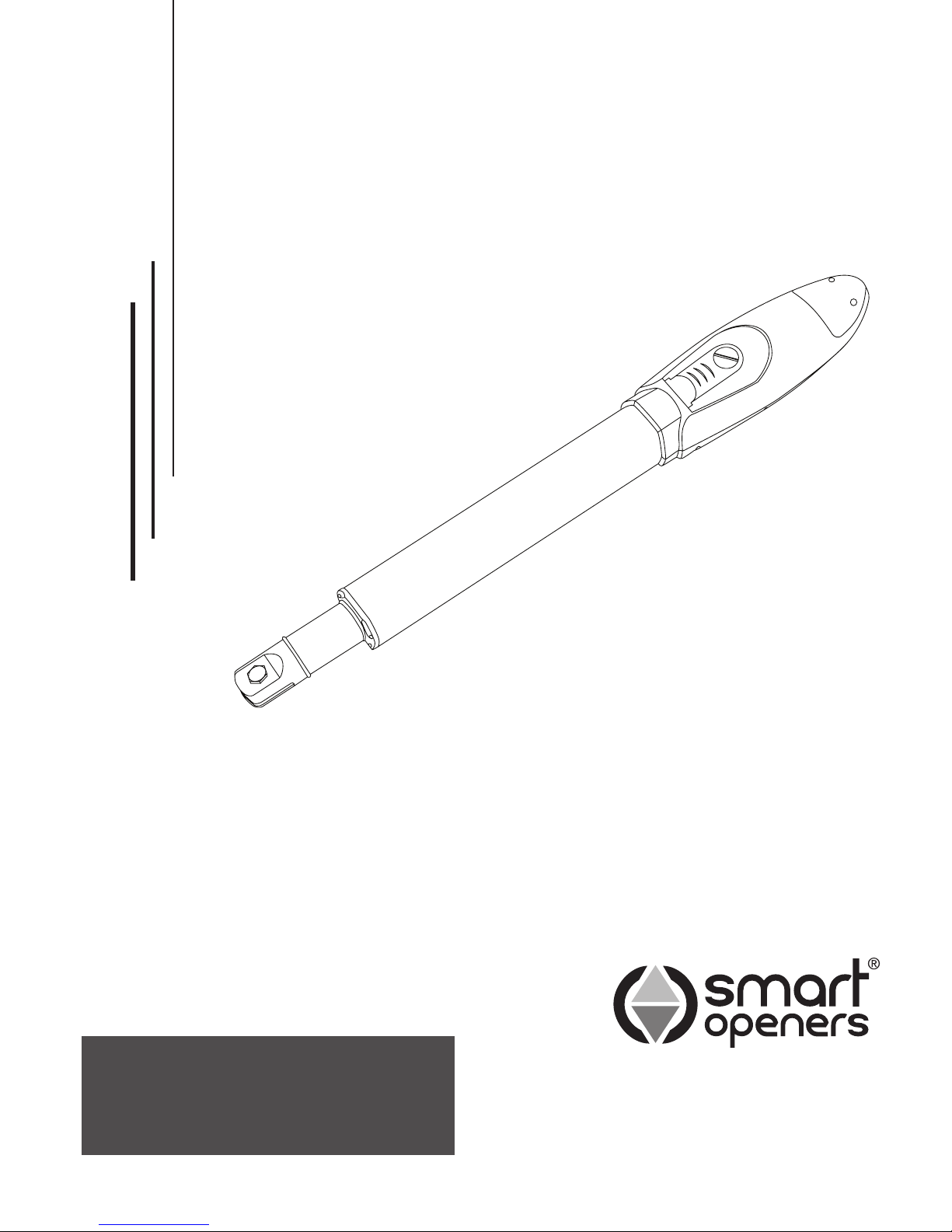
Smart Swing Linear
Swing Gate Opener
WARNING: IT IS VITAL FOR THE SAFETY OF ALL
PERSONS INSTALLING AND USING THIS OPENER TO
FOLLOW THE INSTALLATION INSTRUCTIONS AND
SAFETY WARNINGS. FAILURE TO COMPLY MAY RESULT
IN SERIOUS PERSONAL INJURY AND/OR PROPERTY
DAMAGE AND FAILURE OF THE OPENER SYSTEM.
INSTALLATION MANUAL
Page 2

Index
Kit Contents
Important Safety Warnings
Product Description
Operating Controls
Mechanical Installation
Electrical Connection
Menu Navigation
Quick Reference Guide
Coding Transmitters
Deleting Transmitters
Transmitter Button Allocation
Setting Limits - Dual Leaf Gate
Setting Limits - Single Leaf Gate
Setting Pedestrian Mode
Setting Lock Mode
Setting Obstruction Force Margin
Setting Motor Open/Close Speed
Setting Photo Beam Mode
Setting Auto-Close Mode
Setting Auto-Close Timer Delay
Hands Free Learning
Power Save
Close Delay
Manual Disengagement
Important Information for the User
Maintenance
Final Notes
Technical Specications
Warranty
3
3
3
4
5
8
9
10
11
11
11
12
13
14
14
14
15
15
16
16
16
17
17
17
18
18
18
18
19
To the extent that they may be lawfully excluded, Smart Openers Pty Ltd hereby expressly excludes all
conditions and warranties, statutory or otherwise, which may be implied by law as conditions or warranties
of purchase of a Smart Openers Pty Ltd Gate Opener. Smart Openers Pty Ltd hereby further disclaims
and rejects to the maximum extent permitted by law any liability or responsibility whatsoever for any direct,
indirect, consequential, incidental or other injury, damage, cost, expense or loss whatsoever incurred or
suffered by any person, company, rm or organization as a result of any failure to install the Gate Opener in
accordance with these installation instructions.
No part of this publication may be reproduced, utilised, transmitted, or distributed in any form by any means including
photocopying, recording, mechanical, electronic or otherwise by any party, without the written permission from the publisher
Smart Openers Pty Ltd. Copying without authorisation is ILLEGAL.
© November 2011 Smart Openers Pty Ltd. All rights reserved.
Page 3
-3-
Important Safety Warnings
The Smart Swing gate opener described in this manual is
designed for the automation of residential hinged swing
gates. Any other use is considered improper and will void
the warranty.
WARNING:
You are carrying out operations on machine systems
classied in the automatic gates and doors category and
as such failure to comply with the relevant safety rules
may result in serious personal injury and/or property
damage. Reference to the safety rules can be found on
pages 2-4 of the owners manual and should be read and
understood prior to installation.
Only qualied personnel should install and service the
equipment. It is the responsibility of the installer to adhere
to all relevant safety standards.
The Smart Swing opener is designed and manufactured
to meet all current Australian standards and it is
essential that the installer also installs the equipment in
accordance with all local and Australian regulations.
Unqualied personnel or those who do not know the
occupational health and safety standards applicable
to automatic gates and doors category must under
no circumstances carry out installations or implement
systems.
Persons who install or service the equipment without
observing all the applicable safety standards will be
held responsible for any damage, injury, cost, expense
or claim whatsoever suffered by any person as a result
whether directly or indirectly from failure to install the
system correctly and in accordance with the relevant
safety standards and installation manual.
For a more detailed list of the Safety Warnings and safety
issues associated with the installation and use of a Smart
Swing gate opener refer to the safety warnings in the
OWNERS MANUAL.
Contents
Description
The Smart Swing gate opener requires a 240V AC 50Hz
power input. The 24V DC motor can provide remote
control and automatic modes for operation. When the
gate is in operation, movement can be interrupted by
activation of the safety inputs (transmitter, wall switch (if
tted) and photo beams (if tted).
An encoder sets open and close positions and braking
during the end of the travel cycle reducing speed and
noise.
A 433.22MHz radio receiver is built into the circuit board
and the rolling code is memorised with the self-learning
technique. As an alternative to the built-in receiver the
unit will accept any of the range of stand alone radio
receivers. The unit has been designed to provide
maximum reliability, safety and exibility of use.
IMPORTANT:
Before starting to install the unit read all of the
instructions carefully and make sure you are familiar
with the safety warnings included in this manual and
in the OWNERS MANUAL.
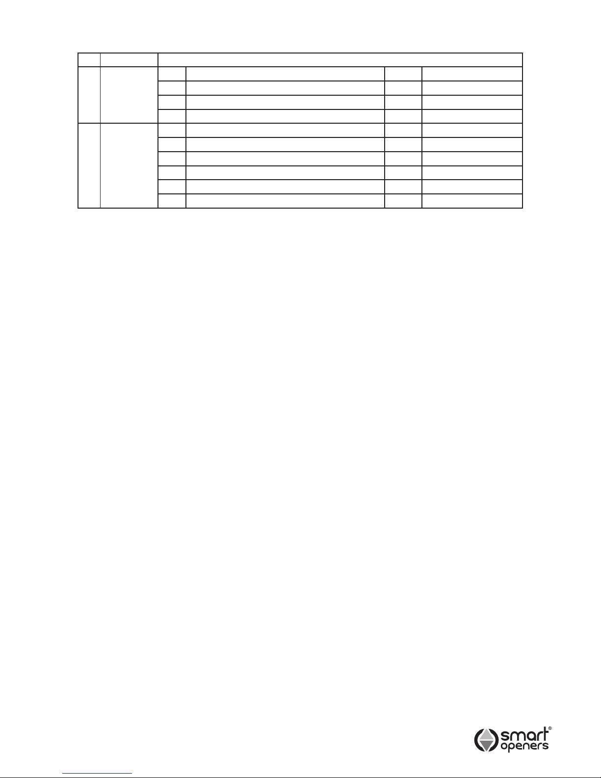
No Package Part
1 Motor No Description Qty Remark
1 Motor 1 Set
2 Motor Mounting Brackets 2 Pcs
2 Motor Fixing Bolts 2 Pcs
2 Controller 3 Logic Controller 1 Pc
4 Logic Controller Mounting Hardware 1 Pc
5 Transmitter 2 Pcs Smart Pet Transmitter
6 Motor Connector Cable 1 Pc
7 Installation Manual 1 Pc
8 Owners Manual 1 Pc
© November 2011 Smart Openers Pty Ltd
Page 4
-4-
© November 2011 Smart Openers Pty Ltd
Operating Controls
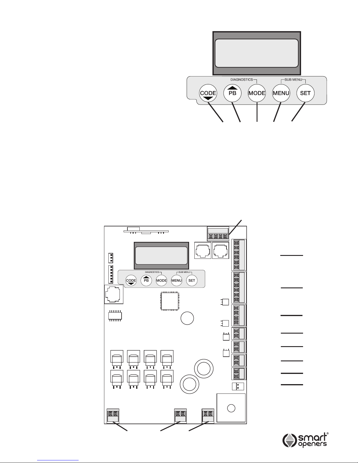
1. CODE button - for coding transmitters.
2. PB button - Open/Stop/Close.
3. MODE Button - Save setting and exit to normal
operation mode.
4. MENU Button - Function/Parameter select.
5. SET Button - Save changes and move to next
function.
Circuit Board Connectors
6. Connector for motor 1.
7. Connector for motor 2.
8. Connector for backup battery.
9 . Connector for encoders.
10. Connector for controlling inputs.
11. Connector for motor limits input (Not used on Swing).
12. Connector for photo beam.
13. Connector for pulse/magnetic lock.
14. Connector for DC ashing light or similar (5A max).
15. Connector for DC courtesy light or similar (5A max).
16. Connector for solar panel or external DC charger.
17. Connector for controller power from transformer.
Smart Openers
SC Vx.xx
1 2 3 4 5
6 7 8
Com
Push Btn
Pedestrian
Stop
Close
Open
M2 Open Limit
Com
M2 Close Limit
M1 Open Limit
Com
M1 Close Limit
Com
Photo Beam 2
Photo Beam 1
+24V
Lock +
Lock -
Activity 2 +
Activity 2 -
Activity 1 +
Activity 1 -
DC Charger DC Charger +
24V AC
-
Encoder 2
Encoder 1
+
Encoder 2 Encoder 1
Motor 1 Motor 2
24V Battery
Back Up
RS-232
Interface for site
maintenance
Smart Openers
SC Vx.xx
9
10
11
12
13
14
15
16
17
RF Receiver
Page 5
-5-
Installation
Remember there are specic standards that have to
be strictly followed regarding the safety of electrical
installations and automatic gates and doors.
As well as the legal requirements and standards that
must be adhered to, please take note of the following
points to ensure maximum safety and reliability of your
installation.
1. Prior to installing check the surrounding environment.
Carefully evaluate any hazards there could be from
physical damage (transiting vehicles, parts of trees
falling etc.), possible contact with foreign bodies
(insects, leaves, etc.), Flooding hazards or any other
exceptional events.
2. Check that the mains voltage is the same as that
given on the rating plate and in this manual.
3. Check there is suitable electrical protection against
short circuits/power spikes and proper earthing on the
mains supply.
Remember the unit has mains voltage running through it
(electrocution hazard, re hazard, etc).
4. Take care with the control unit; parts may be subject
to damage if abused.
5. Make sure you have all the necessary materials and
that they are suitable for this kind of use.
6. Read all the instructions thoroughly and make sure
they are understood before attempting to install the
Smart Swing.
7. Before starting the installation, carefully analyse all
the risks relating to automating the gate. Verify that
the gate to be automated is in a sound condition
and that the mechanisms are in good working order;
observe the safety margins and minimum distances.
8. Evaluate with particular care the safety devices to be
installed and where to install them; always install an
emergency stop device for interruption of power to the
opener if required.
9. Once the risks have been analysed, install the Smart
Swing opener and relative safety devices, emergency
stop and/or photoelectric cells.
Important: For additional safety Smart Openers Pty Ltd
strongly recommends the tting of Photo Electric safety
beams on all installations.
10. When installing the Smart Swing Linear opener,
strictly follow all the instructions given in the
instruction manual. If some points or procedures
in this manual are not very clear do not install the
unit until all doubts have been cleared up with our
technical department.
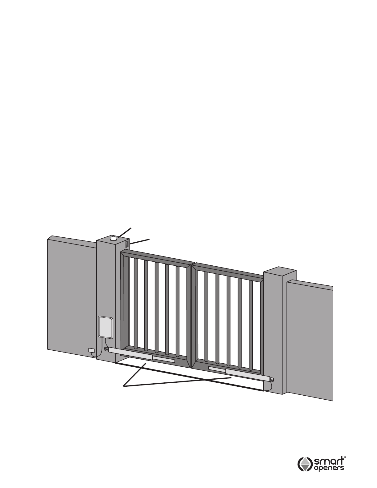
Refer to above for recommended installation
1. Smart Swing gate opener piston
2. Smart Controller
3. 240V AC Power point
4. Motor drive cable conduit
5. Digital Entry Keypad
6. 24V DC ashing light (optional extra)
1
2
5
6
3
4
© November 2011 Smart Openers Pty Ltd
Page 6
-6-
Installation
1. Read the instructions carefully.
2. Make sure the gate and fence structure is solid and
suitable to be motor driven. A strong base on the
gate is required for securing the gate bracket and an
appropriate mounting surface (on the pier or post) for
the Smart Swing opener.
Note: Do not use this opener on solid clad gates. Wind
load can damage the drive system. 1m2 of cladding
area = 400kg wind load at pivot point at 40 knots.
3. Make sure that the gate moves smoothly and there
are no friction points.
4. The gate must be properly balanced and must be
easily moved by hand.
5. Make sure that a 240V, adequately protected 3-pin
power outlet is installed within 1m of where the Smart
Swing opener control box is going to be tted.
Important: Ensure that the Smart Swing Linear opener
is not positioned too low on the gate. The
cable must not drag on the ground. This will
damage the cable and the opener which may
also cause irreparable damage to the control
board and will void the warranty.
Winding Out The Opener
IMPORTANT: The Smart Swing opener is supplied
fully retracted. Before mounting the gate bracket on
the main stay of the gate make sure the opener is
wound out to the full extent of its travel as per below.
1. Connect the drive unit cable to the control box.
2. Connect the control box to power. The controller will
perform a software check and then display Positions
Not Set (Fig. 8 on Pg 9).
3. Press SET the display will show Motor Extend Press
PB.
4. Press and release PB to wind out the drive unit.
The controller will beep when maximum extension is
reached. The display will then show MODE = EXIT
SET = SETUP.
5. Press MODE to exit.
Note: For a dual leaf gate installation, repeat above
procedure for the second drive unit then disconnect
from power and then disconnect the motor cable..
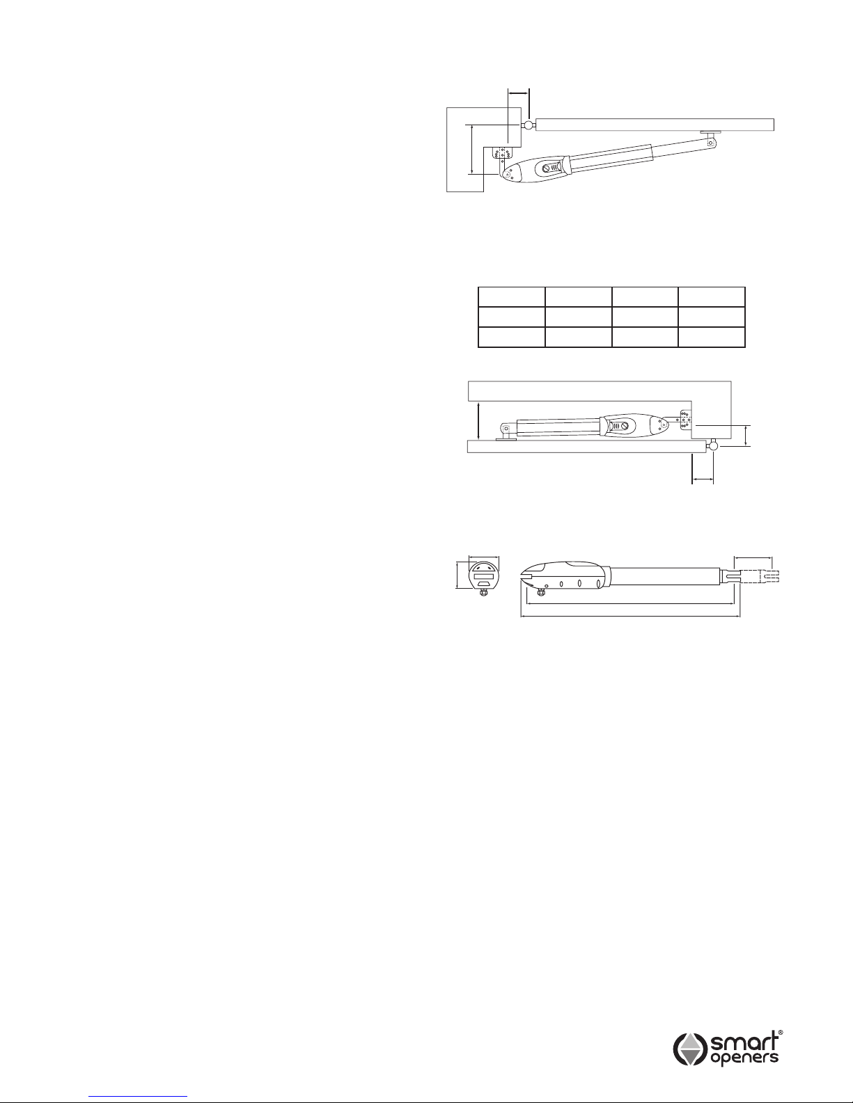
Table 1 - Gate Geometry
A (mm) B (mm) TRAVEL
Min 70 150 220
Max 190 160 350
B
A
Fig. 1
Fig. 3
350
115
106
797
844
MAX
150
MIN
70
MIN
150
© November 2011 Smart Openers Pty Ltd
Fig. 2
Page 7
-7-
© November 2011 Smart Openers Pty Ltd
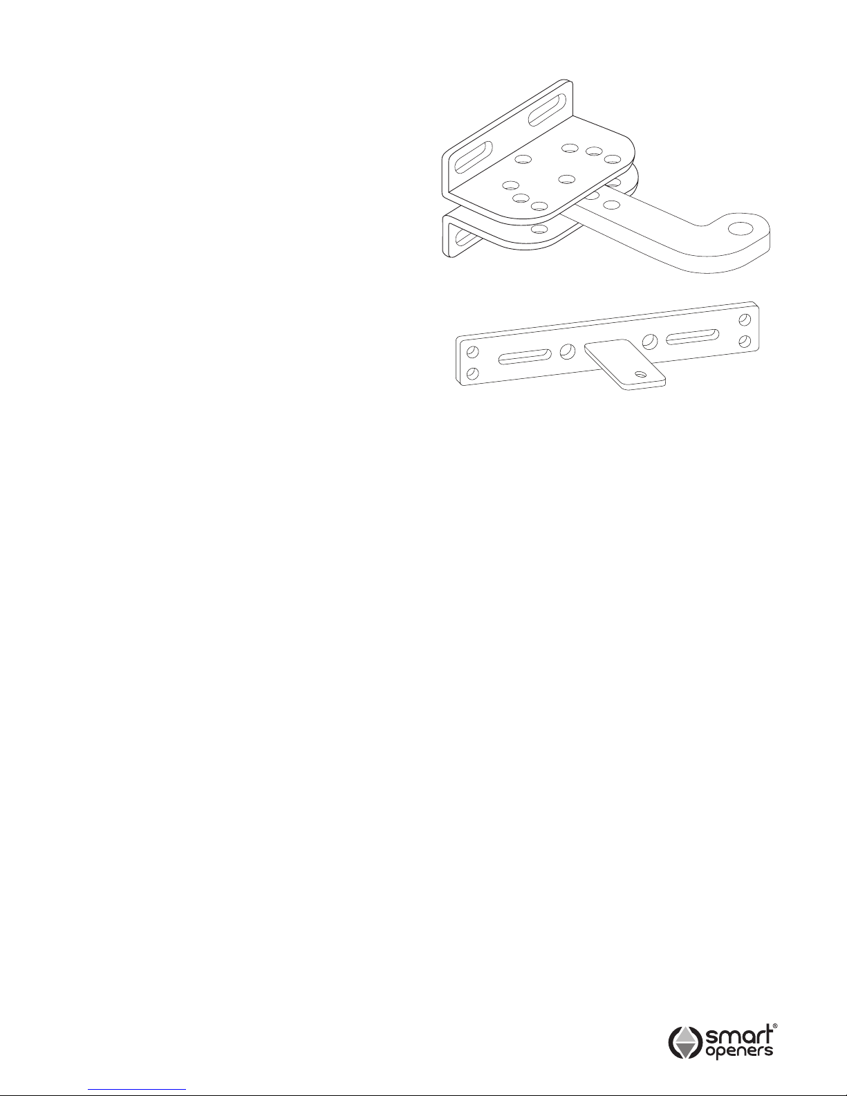
Fig. 4
Post Bracket
Gate Bracket
Positioning The Opener
1. Use Fig. 1 and the geometry table to determine
the optimum position for the drive unit taking into
consideration the desired arc (angle) of travel and
sideroom requirement.
2. Mark the location of the pier/post mounting bracket.
If suitable use the enclosed bracket (Fig. 4) which is
punched with multiple holes for a variety of angles,
otherwise fabricate one to suit.
3. Locate the drive unit on the post bracket. Close
the gate and mark the location of the gate bracket.
Ensure that the drive unit is level.
4. Fix the gate bracket in place using the slotted holes.
Position the bolts in the middle of the slots to allow for
ne adjustment after installation.
Note: Using bolts will provide a much more secure tting
of bracket to gate than self tapping (Tek) screws.
5. Tighten bolts and test opener to see that it closes in
the correct position. If the gate doesn’t close in the
desired position, release bolts, adjust bracket position,
retighten bolts and retest.
6. Once satised with the bracket position retighten bolts
in slots add a minimum of two screws/bolts to holes
provided in the bracket to complete installation.
Important: If the close position needs further adjustment,
move the gate bracket position. Do not
overdrive the motor to close as this could
invoke an obstruction detection causing gate
to fully close and then reopen.
Page 8
LEARN
P/B
MODE MENU SET
M1 M2
LEARN
P/B
MODE MENU SET
M1 M2
HALL
GND
GND
+5V
(H2)
(–)
(–)
(+)
HALL
GND
GND
+5V
(H2)
(–)
(–)
(+)
-8-
Electrical Connection
WARNING Do not x the control box or junction box
upside down. This will cause water and/or condensation
to enter through the cable glands and will void the
warranty.
Motor Connection for Single Leaf Gate
For single leaf gate the opener is prewired ready for set
up. Simply connect the motor connector cable from the
controller to the motor.
Go to page 11 to code transmitters then page 11 for limits
set up procedure.
Motor Connection for Two Leaf Gate
For a two leaf gate a junction box is required with
connection via a 5-core cable or 2-core for motor power
plus RJ45 positioning encoder cable (supplied in your
kit). Ensure that the cable is properly protected with a
cable gland at each end and a suitable conduit across or
under the driveway.
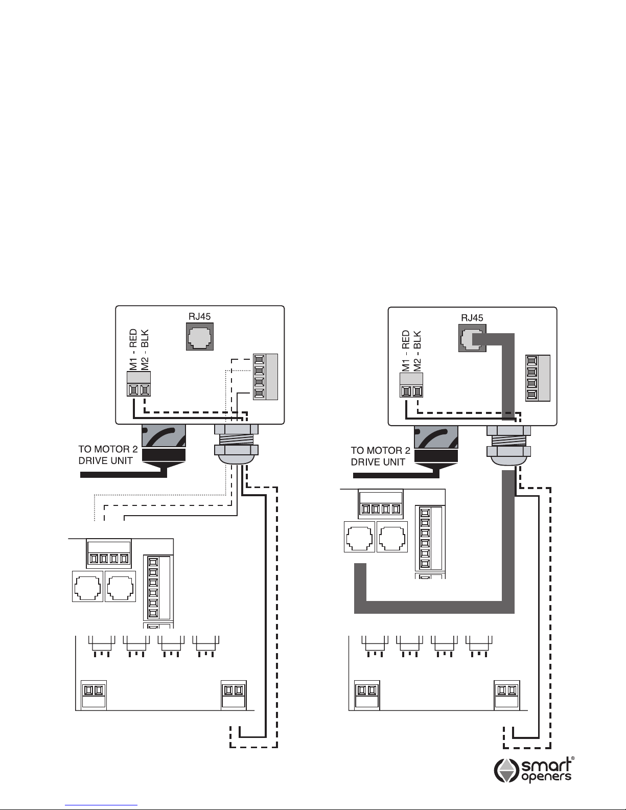
Note: Motor 1 is the primary opener and opens rst. The
leaf that has the trailing edge/overlap is opened by
motor 2. If you need to swap the motors over so
that the overlap is on the same side as the control
box swap the motor and encoder wires over.
Connect 5-core cable from Motor 2 and encoder
terminals in the control box to the Motor 2 Junction Box
as per wiring diagram (Fig. 5).
Alternatively use an RJ45 cable for the encoder
connection as per Fig. 6.
Fig. 5 Fig. 6
Com
Push Btn
Ped
Stop
Close
Open
Com
Push Btn
Ped
Stop
Close
Open
MOTOR 2
JUNCTION BOX
MOTOR 2
JUNCTION BOX
MOTOR CONNECTION
WITH 5-CORE CABLE
MOTOR CONNECTION
WITH RJ45 CABLE
2 1
BLACK BLACK
RED RED
2 12 1 2 1
-H2H1
+
Encoder 2 Encoder 1
Encoder 2 Encoder 1
© November 2011 Smart Openers Pty Ltd
Page 9
-9-
Powering Up
1. Inspect the power cable for damage. Ensure that the
cable will not interfere with the moving gate or the
drive unit.
2. Connect to power. The opener will perform a software
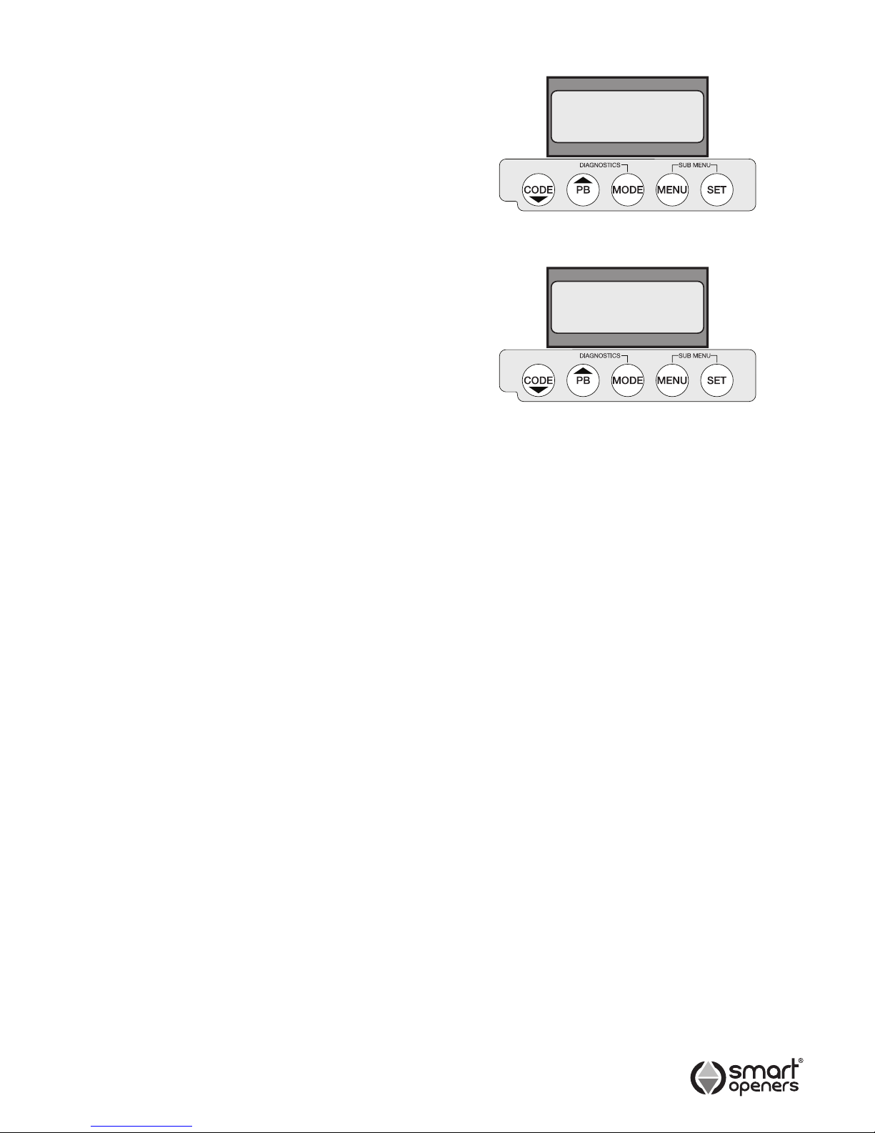
check before displaying the welcome screen (Fig. 7).
3. The LCD will then display the default motor position
setting Positions Not Set (Fig. 8).
Menu Navigation
l
Use the CODE button to code transmitters and to cycle
up through parameters.
l
Use the PB button during normal operation to open/
stop/close the gate.
l
Pressing MODE at any time will store changes and exit
to main screen.
l
Use the MENU button enter parameter menu and to
cycle through parameter options or increase value.
l
Press the SET button to enter limits set up and to
conrm changes and move to the next menu item.
© November 2011 Smart Openers Pty Ltd
Smart Openers
SC Vx.xx
Positions
Not Set
Fig. 7
Fig. 8
Page 10
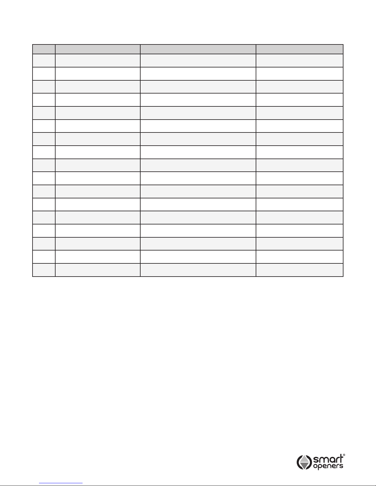
Menu Item Factory Default Options
1 Pedestrian Mode Off On/Off
2 Lock Pulse Pulse/Hold (Magnetic)
3 Obstruction Setting 03 00 – 09
4 Open Speed 80% 50%-100% (by 5%)
5 Close Speed 80% 50%-100% (by 5%)
6 Motor Delay On (only for Dual Motor) On/Off
7 Photo Beam Off On/Off
7.1 PE Close Off (only for Photo Beam Mode) On/Off
7.2 Sequence Mode Off (only for Photo Beam Mode) On/Off
8 Auto Close Off (only for Photo Beam Mode) On/Off
8.1 Time Delay 30 secs 5-400 secs
8.2 PED Close Off On/Off
8.3 PED Time Delay 30 secs 5-400 secs
9 Transmitter Button PB=1 PD=2 PB, PD, OP, CL
10 Hands Free Learn On On/Off
11 Power Save Off On/Off
12 Close Delay 5 Sec 0-10 secs
-10-
Menu Quick Reference Guide
Use the table below as a reference to guide you through
the menu system and parameters.
Note: If Photo Beam (No. 7) is off next item is TX Button
Allocation (No. 9).
If PE Close (No. 7.1) is on then Sequence Mode
(No. 7.2) is not available.
Close Delay (No. 12) is only available when Dual
Motor is selected during set up.
© November 2011 Smart Openers Pty Ltd
Page 11
-11-
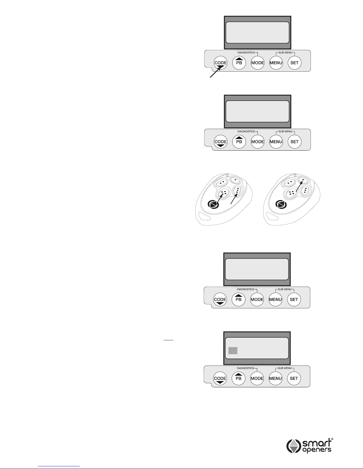
Coding Transmitters
Note: The button you choose (1-4) for the rst TX you
code will be the same button for all subsequent
transmitters. Up to 200 TXs can be stored into
memory. If more than 200 are stored the system
will disregard any attempts to code new TXs.
1 Press the CODE button for 2 seconds the display will
show Code Learn (Fig. 9).
2 Choose which transmitter button will operate the gate
and press that button twice.
The rst press will allocate a number to the remote
and the display will show Remote XXX (Fig. 10), on
the second press the display will show CODE SET.
Test the transmitter - the opener will beep to conrm.
Repeat the above steps to code additional transmitters.
Remote TX Coding (Hands Free Learning)
It is possible to code new transmitters via an already
coded remote without being in contact with the control
panel. This is useful if more than one device is operated
by the transmitter. This also takes the guess work out of
button allocation as this is done automatically.
1 Ensure Hands Free Learning is enabled (page 17).
2 Press TX BUTTON 3 + 4 together for 2 seconds. The
opener will beep to signal Code Learn Mode.
3 Press any button on new transmitter twice (Fig. 11).
The opener will beep to conrm code learned.
Deleting One Transmitter
This is useful if the transmitter is lost and the transmitters
reference number is known.
1 Press and hold the CODE button for 5 seconds. The
display will show Del Remote ALL (Fig. 12).
2 Press SET to scroll up or PB to scroll down to
required transmitter number - e.g. Remote 023.
3 Press CODE for 3 secs to delete.
Deleting All Transmitters
1 Press and hold the CODE button for 5 seconds, the
display will show Del Remote ALL (Fig. 12).
2 Press CODE for 3 secs to delete.
Transmitter Button Allocation
Note: The following procedure alters these settings for ALL
coded transmitters.
1. Press MENU for 3 secs. Press SET to cycle through
to Transmitter Allocation menu (Fig. 13). The LCD will
display functions on the rst line and button allocation
on the second.
2. Press PB to cycle through buttons 1–4 (0 to disable).
Note: To allocate ALL BUTTONS to the same function
press and hold PB until display show All.
3. Press MENU to allocate the button and move to the
next function and repeat as required.
4. Press MODE to save and exit to normal operation.
Note: If a button is already allocated to one function it will
not be available for any other.
© November 2011 Smart Openers Pty Ltd
Remote 001
Del Remote
All
PB PD OP CL
01 02 00 00
Fig. 11
Existing
Remote
Uncoded
Remote
Code Learn
Fig. 9
Fig. 10
Fig. 12
Fig. 13
Page 12
-12-
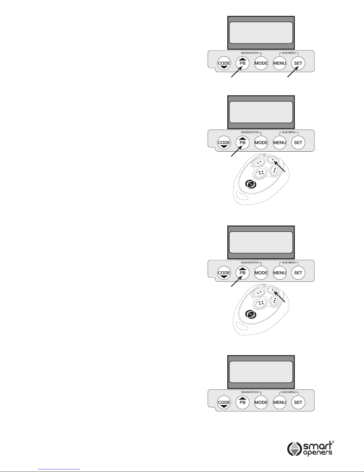
1. Press SET for 3 secs to enter Limits Set Up. The
display will show Motor Extend Press PB.
2. Press PB. The motors should already be full wound
out and the gate fully closed from the initial set up as
per Pg 7 - if the motors are not already wound out as
done previously they will wind out to the fully closed
position. If they are fully wound out the display will
now show MODE = EXIT SET = SETUP.
3. Press SET to enter setup. The display will show Dual
Motor (default). If this is correct press SET to save
and continue to Limits Set Up (Fig. 14).
4. The display will show Motor 1 Set Up (Fig. 15). Press
PB (or TX Button 1) to drive the gate to the desired
open position - release button when this position is
reached.
Note: Adjust if required by pressing CODE (or TX Button
4) to move in close direction.
5. Pause for 5 secs (do not press anything) to conrm
open position set. The controller will beep to conrm.
6. The display will show Motor 2 Set Up. Repeat as per
steps 2 and 3.
7. The display will show Set Up Complete (Fig. 17) for 2
secs and is ready for normal use.
Note: Gate leaf delay is factory preset and is
automatically calculated during the limits set up
procedure.
If you would like to alter the gate delay time after
installation is complete. Please go to Close Delay
section on Pg 17.
Aborting Limits Set Up
To abort limits set up press MENU to exit. To return to set
up mode press SET for 3 secs and repeat as per above.
Setting Limits – Dual Leaf Gate
© November 2011 Smart Openers Pty Ltd
Fig. 15
Fig. 16
Dual Motor
Set Up
Complete
Motor 1
Set Up
Motor 2
Set Up
Fig. 14
Fig. 17
Page 13
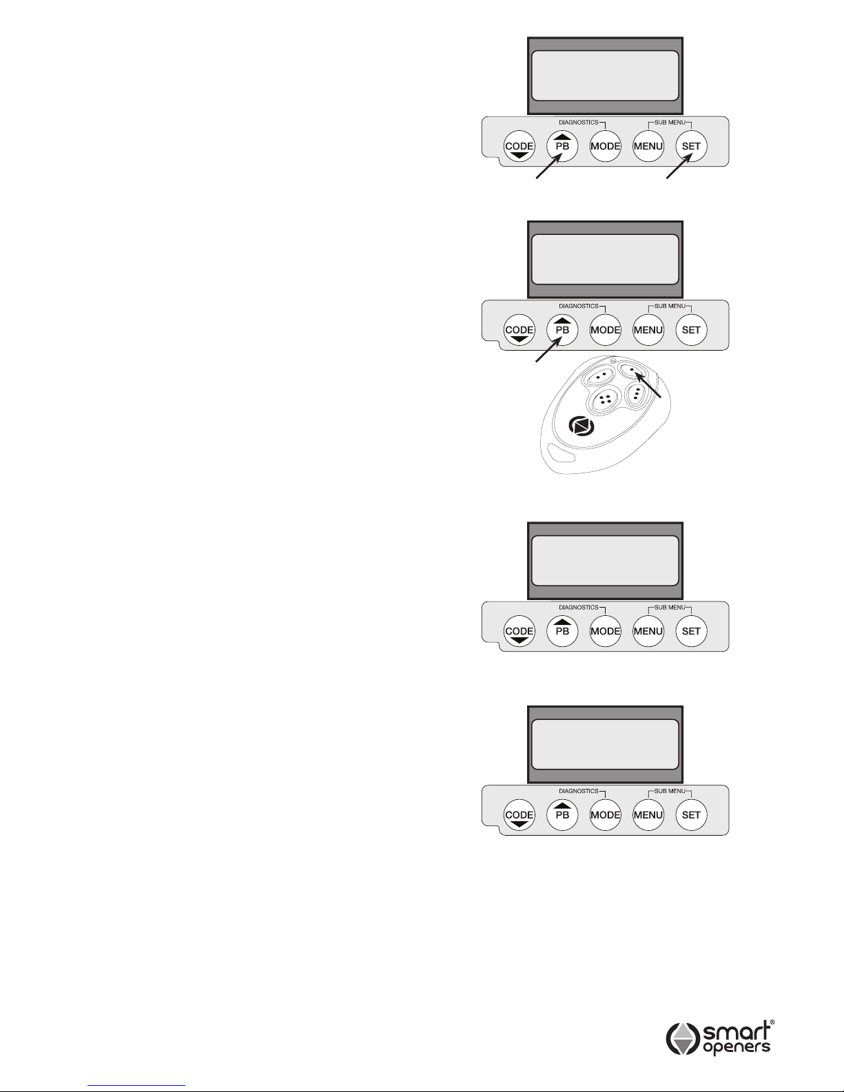
1. Press SET for 3 secs to enter Limits Set Up. The
display will show Motor Extend Press PB.
2. Press PB. The motor should already be full wound out
and the gate fully closed from the initial set up as per
Pg 7 - if the motor is not already wound out as done
previously it will wind out to the fully closed position.
If they are fully wound out the display will now show
MODE = EXIT SET = SETUP.
3. Press SET to enter setup. The display will show Dual
Motor (default). Press MENU to change to Single
Motor then press SET (Fig. 18).
4. The opener should already be full wound out and the
gate fully closed from the initial set up as per Pg 7 The display will show Motor 1 Set Up (Fig. 19). Press
PB (or TX Button 1) to drive the gate to the desired
open position - release button when this position is
reached.
Note: Adjust if required by pressing CODE (or TX Button
4) to move in close direction.
5. Pause for 5 secs (do not press anything) to conrm
open position set. The controller will beep to conrm.
6. The display will show Set Up Complete (Fig. 21) for 2
secs and is ready for normal use.
Aborting Limits Set Up
To abort limits set up press MENU to exit. To return to set
up mode press SET for 3 secs and repeat as per above.
Setting Limits – Single Leaf Gate
-13-
© November 2011 Smart Openers Pty Ltd
Fig. 19
Single Motor
Current
Mode
Set Up
Complete
Motor 1
Set Up
Fig. 18
Fig. 20
Fig. 21
Page 14
-14-
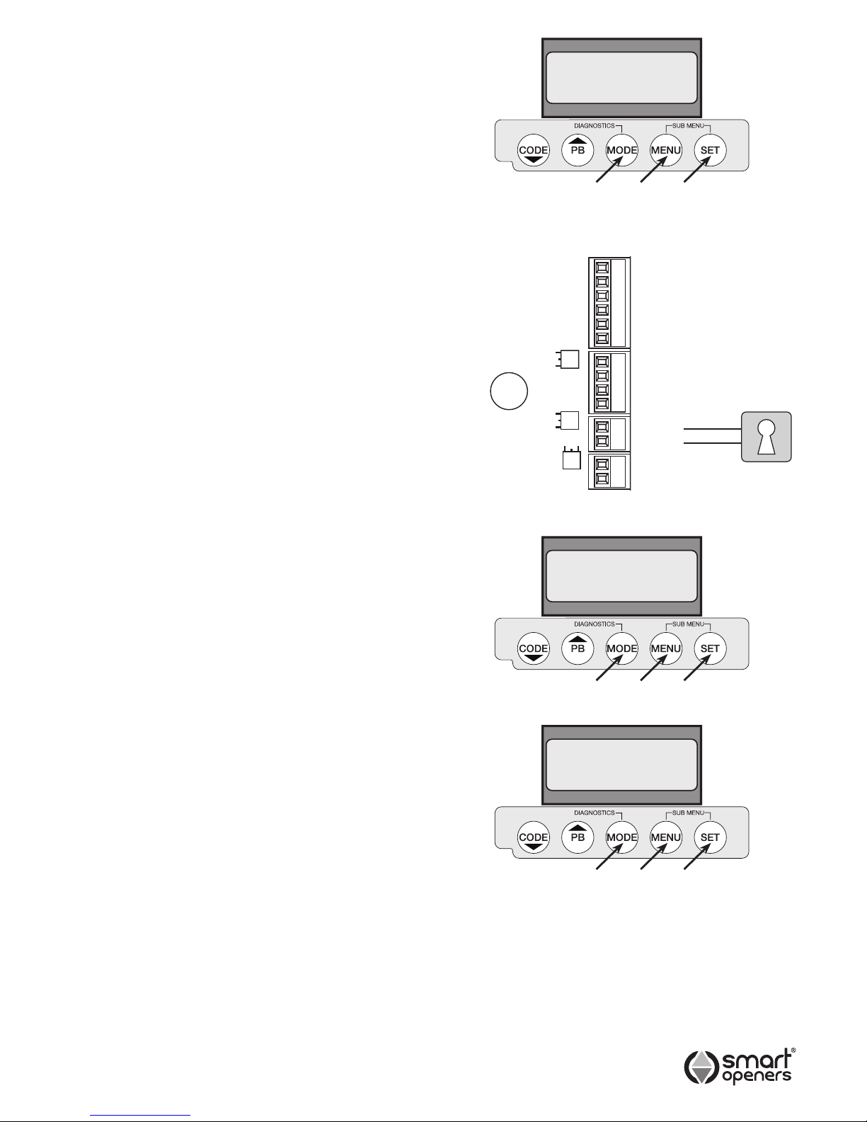
Setting Pedestrian Mode
Pedestrian Mode allows the gate to open partially (or
only one leaf) to allow a person to enter without the need
to open the gate fully as for vehicular access (Factory
Default = Off).
1. Press MENU for 3 secs then SET to cycle though to
Pedestrian Mode.
2. Press MENU to choose On or Off as required.
3. Press SET to conrm or MODE to save and exit.
Note: Pedestrian Mode is factory set to Transmitter
Button 2. If TX button allocation is set to ALL then
Pedestrian Mode will not function.
Setting Lock Mode
Lock Mode allows the gate to utilise to be locked with a
magnetic (hold) or pulse lock for added security. The gate
controller releases the lock momentarily before the gate
commences an open cycle (Factory Default = Pulse).
1. Connect lock to terminal block as per Fig. 24.
2. Press MENU for 3 secs then SET to cycle though to
Lock.
3. Press MENU to choose either Pulse or Hold as
required.
4. Press SET to conrm or MODE to save and exit.
Note: Pulse Mode output for 1 sec prior to motor start.
Hold Mode output 24V once motor has stopped.
Setting Obstruction Margin
The Obstruction Force Margin sensitivity is extremely
important for user safety. Make sure that where possible
the minimum (or default) force required to allow the
gate to travel without phantom reversing is used. Smart
Openers strongly recommend that the gate is properly
serviced rather than increasing the force margin to
compensate (Factory Default = 03).
1. Press MENU for 3 secs then SET to cycle though to
Obstruction Margin (Fig. 25).
2. Press MENU to cycle through from 00 – 09.
3. Press SET to conrm or MODE to save and exit.
Testing Obstruction Margin
1. Test the obstruction force margin sensitivity by placing
a piece of timber approximately 100mm thick between
the gate and the fence post.
2. Close the gate onto the timber. If the gate does not
reverse easily and attempts to continue to close
adjust the force margin as per procedure above.
© November 2011 Smart Openers Pty Ltd
M2 Open Limit
Com
M2 Close Limit
M1 Open Limit
Com
M1 Close Limit
Com
Photo Beam 2
Photo Beam 1
+24V
Lock +
Lock -
Fig. 23
Pedestrian
Mode On
Lock
Pulse
Obstruction
Margin 03
Fig. 22
Fig. 24
Fig. 25
Page 15
-15-
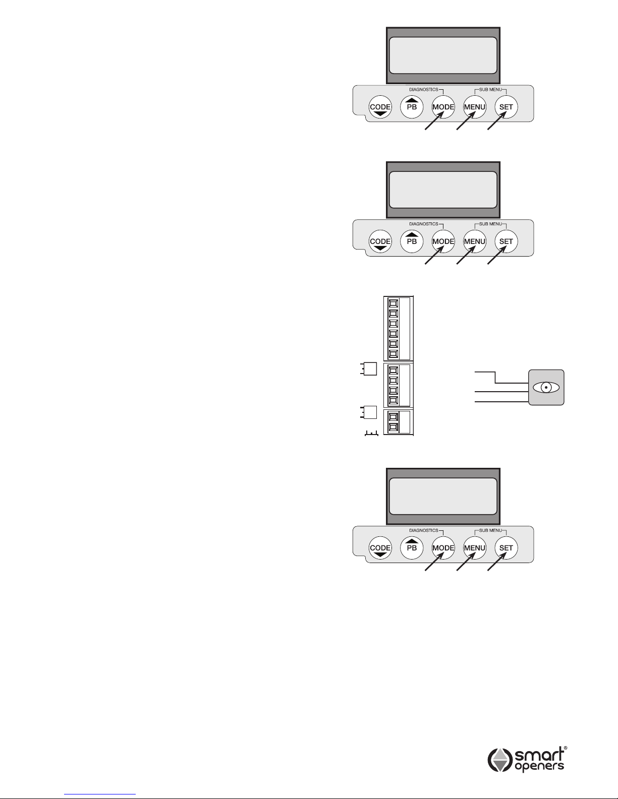
Setting Motor Open and
Close Speeds
If required the opening and closing speed can be reduced
in 5% steps down to 50% to suit the site. This function is
useful if the gate is situated on an incline where gravity
increases natural closing speed (Factory Default = 80%).
1. Press MENU for 3 secs then SET to cycle though to
Open Speed or Close Speed as required.
2. Press MENU to cycle through from 80% down to 50%
in steps of 5%. Once 50% is reached the next press
of the MENU button will return to 100%.
3. When desired speed percentage is reached press
SET to conrm or MODE to save and exit.
Setting Photo Beam Mode
Note: A functioning photo electric safety must be installed
and Photo Beam Mode set to ON to enable autoclose functions.
Photo Beam Mode allows the gate to close once the
beam has been tripped and restored. Smart Openers
strongly recommend the installation of a PE safety beam
to protect persons and property (Factory Default = Off).
1. Connect PE beam cable to controller terminal black
as per Fig. 28.
2. Press MENU for 3 secs then SET to cycle though to
Photo Beam (Fig. 29).
3. Press MENU to choose On.
4. Press SET to conrm or MODE to save and exit.
© November 2011 Smart Openers Pty Ltd
Fig. 28
M2 Open Limit
Com
M2 Close Limit
M1 Open Limit
Com
M1 Close Limit
Com
Photo Beam 2
Photo Beam 1
+24V
Lock +
Lock -
Open Speed
80%
Close Speed
80%
Photo Beam
On
Fig. 26
Fig. 27
Fig. 29
N/O
Page 16
-16-
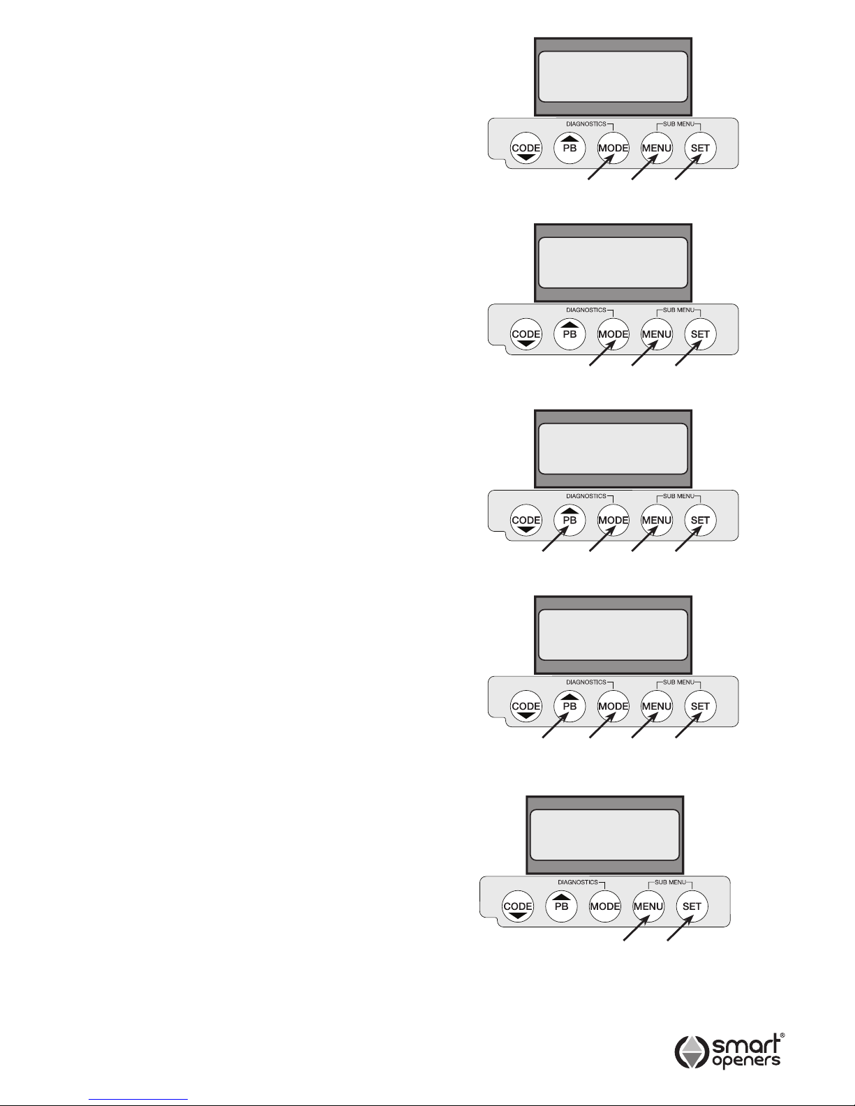
Setting Auto-Close Mode
Auto-Close Mode allows the gate to close automatically
once the PE safety beam has been tripped and the
preset time has elapsed. This function is only available
with the addition of a functioning photo-electric safety
beam (Factory Default = Off).
Auto-Close Mode allows you to set a timer from
001–180 seconds before the gate begins to close. In
this mode the gate will close if the photo beam is not
triggered after the time has elapsed.
Important: If the photo beam is tripped within the time
limit the gate will close 5 secs after the beam is restored.
PE Close Mode allows the gate to close 5 secs after the
photo beam has been tripped.
Important: The gate will remain open until the beam is
tripped.
1. Make sure that a functioning PE beam is connected
and Photo Beam Mode is set to On as per Page 11.
2. Press MENU for 3 secs then SET to cycle though to
Auto-Close or PE Close.
3. Press MENU to choose On.
4. Press SET to conrm or MODE to save and exit.
Setting Auto-Close Timer
Delay
Auto-Close Time delay is used with Auto-Close Mode to
allow the gate to close automatically after the timer has
elapsed.
Note: Auto-Close Mode must be enabled to use this
function.
1. Press MENU for 3 secs then SET to cycle though to
Auto-Close Delay.
2. Press and hold MENU to increase or PB to decrease
delay time in 5 sec increments (Max. 400 secs).
3. Press SET to conrm or MODE to save and exit.
Setting Pedestrian AutoClose and Timer Delay
If Pedestrian Mode is activated the above functions are also
available for Pedestrian Mode. Follow the above procedure
to enable auto-close and set a time delay as required.
Hands Free Learning
Hands Free Learning allows the coding of new transmitters
via an existing already coded remote instead of pressing
the LEARN button. This function is useful if multiple
remotes are to be coded for one site.
(Factory Default = On).
1 To disable this function press MENU for 3 secs then
SET to cycle though to HF Learning On.
2 Press MENU to choose Off (Fig. 34).
3 Press SET to conrm or MODE to save and exit.
© November 2011 Smart Openers Pty Ltd
Auto Close
On
Auto Close
060 secs
PE Close
On
Auto Close
030 secs
Fig. 30
Fig. 32
Fig. 31
Fig. 33
HF Learn
On
Fig. 34
Page 17
-17-
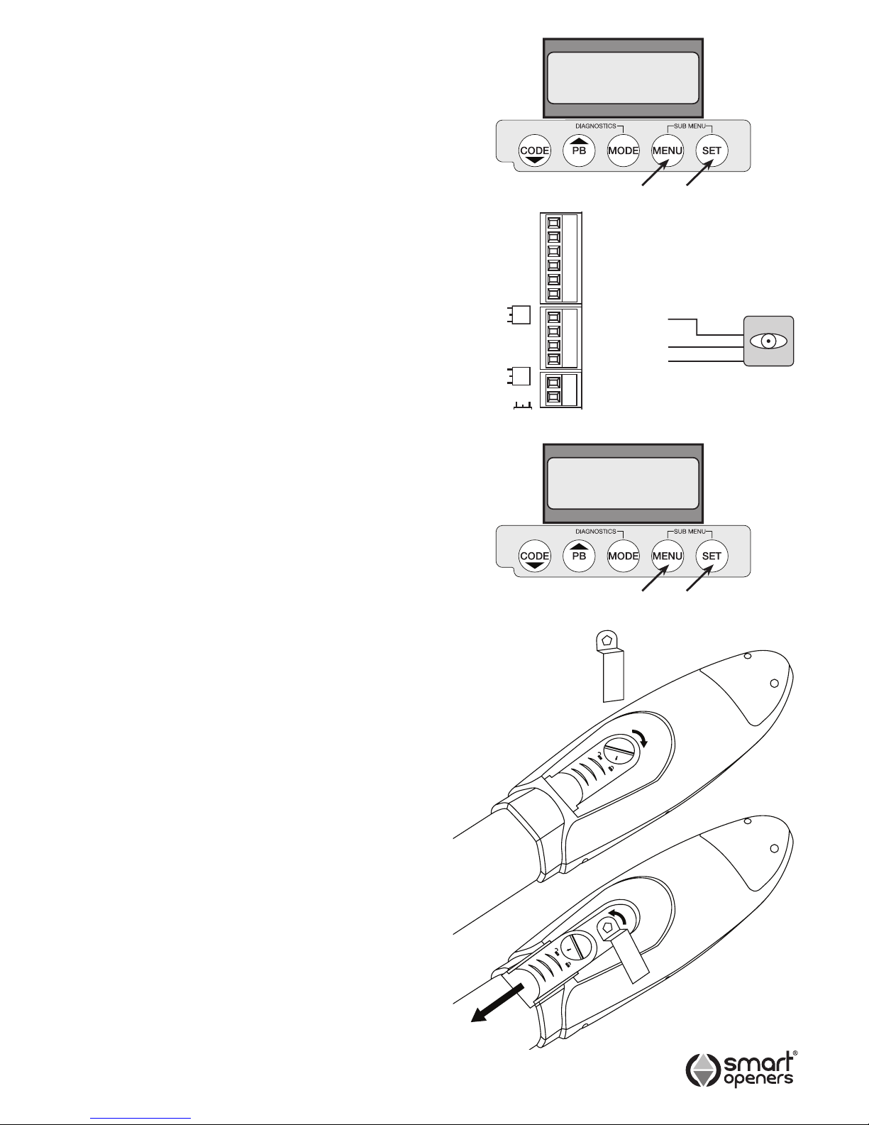
Power Save
Power Save switches off the PE beams after the close
cycle is completed. This reduces load on batteries and
solar powered installations. There is no need to use power
save on mains powered installations
(Factory Default = Off).
Note: Power save will only function if the PE Beam is
wired to the PE Terminal block as per Fig. 36.
1 To enable this function press MENU for 3 secs then
SET to cycle though to Power Save.
2 Press MENU to choose On (Fig. 35).
3 Press SET to conrm or MODE to save and exit.
Close Delay
Close Delay allows you to alter the time delay gap when
the second leaf commences moving in a two leaf gate
installation. (Factory Default = 3 secs).
1 To change setting press MENU for 3 secs then SET to
cycle though to Close Delay.
2 Press MENU to increase time (or press PB to
decrease) by 1 sec up to 10 secs (Fig. 37).
3 Press SET to conrm or MODE to save and exit.
Manual Disengagement
The opener is very easy to disengage to enable you to
open and close the gate manually in case of electrical
failure, system malfunction or re.
Remember: Before disengaging the gate for manual
operation make sure power is off.
For Manual Operation
1. Use the key provided to turn the manual release cover
screw to the open position.
2. Slide the cover down to reveal the release pin.
3. Using the other end of the key turn the pentagonal
release pin anti-clockwise.
To Re-engage the Gate
1. Manually move the gate to the closed position.
2. Re-engage the opener using the key. Lock the release
pin by turning clockwise.
3. Slide release cover back into place and lock with key.
4. Reconnect power and press reset button on the
under-side of control box prior to using in automatic
mode.
IMPORTANT: The opener will not function correctly if the
position reset button is not pressed prior to
use.
Fig. 38
© November 2011 Smart Openers Pty Ltd
Power Save
Off
Close Delay
3 Secs
Fig. 35
Fig. 37
Fig. 36
M2 Open Limit
Com
M2 Close Limit
M1 Open Limit
Com
M1 Close Limit
Com
Photo Beam 2
Photo Beam 1
+24V
Lock +
Lock -
N/O
Page 18

Important Information for
the User
Once the Smart Swing opener has been installed, the
user must be informed about how it works and all the
risks that can arise if it is used improperly. The user must
avoid placing him/herself in dangerous situations such as
standing within the gateway when it is moving.
Do not let children play near the gate and keep the
remote controls out of their reach.
All servicing, repairs or checks must be carried out
by professionally qualied personnel and noted on a
maintenance register kept by the user.
Information for the user is found in the USERS/OWNERS
MANUAL included with this opener.
IMPORTANT: Please make sure the USERS/OWNERS
MANUAL is passed on to the owner prior to leaving the
installation.
IMPORTANT: In case of a malfunction the user must call
an authorised Smart Openers Pty Ltd service technician
and should not attempt to repair the fault themselves.
Maintenance
No particular maintenance is required for the logic circuit
board.
At least twice a year check that the gate is properly
balanced, travelling smoothly and that all working parts
are in good working condition.
IMPORTANT: A poorly operating gate can effect the life of
the automatic opener due to incorrect loads and will void
the warranty.
Check the reversing sensitivity at least twice a year and
adjust if necessary.
Make sure that the safety devices are working effectively
(photo beams, etc.)
Technical Specications
Power Input: 240 VAC ±10% 50Hz
Motor: 24V DC
Working temperature: -10° ~ 60°C
Relative Humidity: <90%
Open and close force: 300N
Receiver frequency: 433.22MHz
Code Capacity: 200 Transmitters
Sensitivity: >1V for correct receiver signal
(average range 50m, with an
aerial)
Decoding: Rolling code
Transmitter power: 27A 12V Battery
NOTE: Smart Openers Pty Ltd reserves the right to
modify its product and product specications at any
time without prior notice.
Final Notes
This manual is only for use by technical personnel
qualied to carry out the installation.
No information given in this manual can be considered of
any interest to the end user.
No setting or adjustments contained in this manual
should be carried out by the end user.
It is important for the installer to show their clients correct
operational use of the Smart Swing including the use of
the manual disengagement lever.
Inform the owner about the need for regular and accurate
maintenance, especially regarding a regular check of the
safety and reversing devices.
-18-
© November 2011 Smart Openers Pty Ltd
Page 19

Warranty and Exclusion of Liability
1. This warranty is an addition to any conditions or warranties that are implied by relevant statute, including the Trade Practices Act 1974 (Cth),
which cannot be excluded or negated.
2. Subject to all of the matters set out below, Smart Openers Pty Ltd (“Smart Openers “) warrants:
(a) swing and sliding gate opener drive units for twelve (12) months
(b) roll-up and overhead door opener drive units for twenty four (24) months
(c) all components and accessories for twelve (12) months,
from the date of purchase (specied in the sales docket receipt) as free of any defects in material and workmanship.
3. This warranty applies only where the purchaser:
(a) immediately noties Smart Openers or the retailer of the alleged defect;
(b) returns the product to Smart Openers or the retailer; and
(c) presents the relevant sales docket and this warranty document to the retailer and, if so requires, to Smart Openers to conrm the
date of purchase.
4. Defects or damage partly or wholly due to any of the following causes are not covered by this warranty:
(a) accidental damage to any of the Product or to the Product’s components;
(b) normal wear and tear to the Product or to the Product’s components;
(c) ood, rain, water, re, lightning , storms, any acts of God, contamination or pollution;
(d) incorrect, improper, inappropriate or unreasonable maintenance and/or use;
(e) installation, adjustment or use which is not in accordance with the instructions set out in installation instructions incorporated in the
document;
(f) attempted or complete modication or repairs to the Product or tampering with the Product carried out by a person who is not
authorised by Smart Openers to carry out such modication or repairs;
(g) faulty or unsuitable wiring of structure to which the Product is xed or connected;
(h) radio (including citizen band transmission) or any electronic interference;
(i) blown fuses or damage caused by electrical surges, power surges or power spikes;
(j) damage caused by insects or any infestation;
(k) negligence or deliberate damage.
5. Except for this warranty, Smart Openers gives no warranties of any kind whatsoever (whether express or implied), in relation to the product,
and all warranties of whatsoever kind relating to the product are, to the extent permissible by statute, hereby excluded and negated.
6. To the extent permissible by statute, Smart Openers disclaims any liability of whatsoever nature in respect of any claim or demand for loss or
damage which arises out of:
(a) accidental or deliberate damage to, or normal wear and tear to, the product or to the product’s components;
(b) any cost relating to damage resulting from wear and tear;
(c) blown fuses, loss or damage caused by electrical surges, power surges or power spikes;
(d) loss or damage due to theft, re, ood, rain, water, lightning, storms, any acts of God, contamination or pollution;
(e) door or gate not in safe and correct working order and condition;
(f) evidence of unauthorised repairs;
(g) any cost relating to damage caused deliberately or by misuse, negligence or failure to maintain the equipment in a proper working
order, including (without limitation) due to anything described in paragraphs (d) and (e);
(h) installation, adjustment or use which is not in accordance with the instructions set out in installation instruction manual and owners
manual;
(i) attempted or complete modication or repairs to the Product or tampering with the Product carried out by a person who is not
authorised or has not been trained by Smart Openers to carry out such modication or repairs;
(j) faulty or unsuitable wiring of structure to which the Product is xed or connected;
(k) radio (including citizen band transmission) or any electrical interference;
(l) damage caused by insects or any infestation;
(m) loss or damage to any property whatsoever or any loss, damage or expense whatsoever resulting or arising therefrom;
(n) any consequential, indirect, special or incidental loss or damage;
(o) any cost or expense arising due to manufacturer recall of any product;
(p) any cost or expense due to negligence of the approved service provider;
(q) installation of a residential garage door or gate opener in a commercial or industrial situation or a non-single residential dwelling.
7. Smart Openers liability under this warranty is limited, at Smart Openers absolute option, to replacing or repairing the product which Smart
Openers, in its unfettered and absolute opinion, considers to be defective either in material and/or workmanship or to credit the dealer with
the price at which the product was purchased by the dealer.
8. This warranty does not extend to cover labour for installation.
9. This warranty is limited to Return-to-Base (RTB) repair and does not cover labour for on-site attendance.
10. This warranty is void if the Product is not returned to the manufacturer in original or suitably secure packaging.
11. This warranty is only applicable for repairs to the Product carried out within Australia and for Product in Australia.
12. This warranty does not cover consumable items including globes, batteries and fuses.
13. This warranty is not transferable.
14. Where the Product is retailed by any person other than Smart Openers , except for the warranty set out above, such person has no authority
from Smart Openers to given any warranty or guarantee on Smart Openers behalf in addition to the warranty set out above.
Notes:
1. This warranty is to be read in conjunction with the installation manual and owner’s manual.
-19-
© November 2011 Smart Openers Pty Ltd
Page 20

Smart Openers Pty Ltd
PO Box 6666 GCMC, Qld 9726
Tel: 1300 366 547 Fax: 1300 366 972
Email: [email protected]
Web: www.smartopeners.com
© November 2011 Smart Openers Pty Ltd. All rights reserved.
No part of this publication may be reproduced, utilised, transmitted, or distributed in any form by any means including photocopying, recording,
mechanical, electronic or otherwise by any party, without the written permission from the publisher Smart Openers Pty Ltd. Copying without
authorisation is ILLEGAL. In an ongoing commitment to product quality and innovation Smart Openers reserves the right to change and alter
specications and model numbers and types without notice.
D/N: SWLIM0041212
 Loading...