

Page 1

WARNING: IT IS VITAL FOR THE SAFETY OF ALL
PERSONS INSTALLING AND USING THIS OPENER TO
FOLLOW THE INSTALLATION INSTRUCTIONS AND
SAFETY WARNINGS. FAILURE TO COMPLY MAY RESULT
IN SERIOUS PERSONAL INJURY AND/OR PROPERTY
DAMAGE AND FAILURE OF THE OPENER SYSTEM.
smart
openers
Smart Lifter
Sectional Door Opener
INSTALLATION MANUAL
Page 2

Index
CONTENTS
IMPORTANT SAFETY WARNINGS
DESCRIPTION
OPERATING CONTROLS
INSTALLATION INSTRUCTIONS
SHORTENING THE TRACK
INSTALLING SHUTTLE STOP
DESCRIPTION OF THE CONNECTIONS
PROGRAMMING THE UNIT
SETTING OF OPEN AND CLOSE POSITIONS
ADJUSTMENTS
FUNCTION MODES
PHOTO BEAMS
TO SET AUTO-CLOSE ON/OFF
TO SET TIME DELAY FOR AUTO-CLOSE
SELF-LEARNING TRANSMITTER
MAINTENANCE
TECHNICAL SPECIFICATIONS
FINAL NOTES
INFORMATION FOR THE USER
WARRANTY
3
3
3
4
5
6
8
8
8
9
9
9
9
9
9
10
10
10
10
11
12
To the extent that they may be lawfully excluded, Smart Openers Pty Ltd hereby expressly excludes all
conditions and warranties, statutory or otherwise, which may be implied by law as conditions or warranties
of purchase of a Smart Openers Pty Ltd Garage Door Opener. Smart Openers Pty Ltd hereby further
disclaims and rejects to the maximum extent permitted by law any liability or responsibility whatsoever for
any direct, indirect, consequential, incidental or other injury, damage, cost, expense or loss whatsoever
incurred or suffered by any person, company, rm or organization as a result of any failure to install the
Garage Door Opener in accordance with these installation instructions.
Page 3
-3-
Important Safety Warnings
The Smart Lifter garage door opener described in this
manual is designed for the automation of residential
sectional overhead doors and one piece overhead tilting
doors. Any other use is considered improper and will void
the warranty.
WARNING:
You are carrying out operations on machine systems
classied in the automatic gates and doors category and
as such failure to comply with the relevant safety rules
may result in serious personal injury and/or property
damage. Reference to the safety rules can be found on
pages 2-4 of the oweners manual and should be read
and understood prior to installation.
Only qualied personnel should install and service the
equipment. It is the responsibility of the installer to adhere
to all relevant safety standards.
The Smart Lifter opener is designed and manufactured
to meet all current Australian standards and it is
essential that the installer also installs the equipment in
accordance with all local and Australian regulations.
Unqualied personnel or those who do not know the
occupational health and safety standards applicable
to automatic gates and doors category must under
no circumstances carry out installations or implement
systems.
Persons who install or service the equipment without
observing all the applicable safety standards will be
held responsible for any damage, injury, cost, expense
or claim whatsoever suffered by any person as a result
whether directly or indirectly from failure to install the
system correctly and in accordance with the relevant
safety standards and installation manual.
For a more detailed list of the Safety Warnings and safety
Issues associated with the installation and use of a Smart
Lifter sectional door opener refer to the safety warnings in
the OWNERS MANUAL.
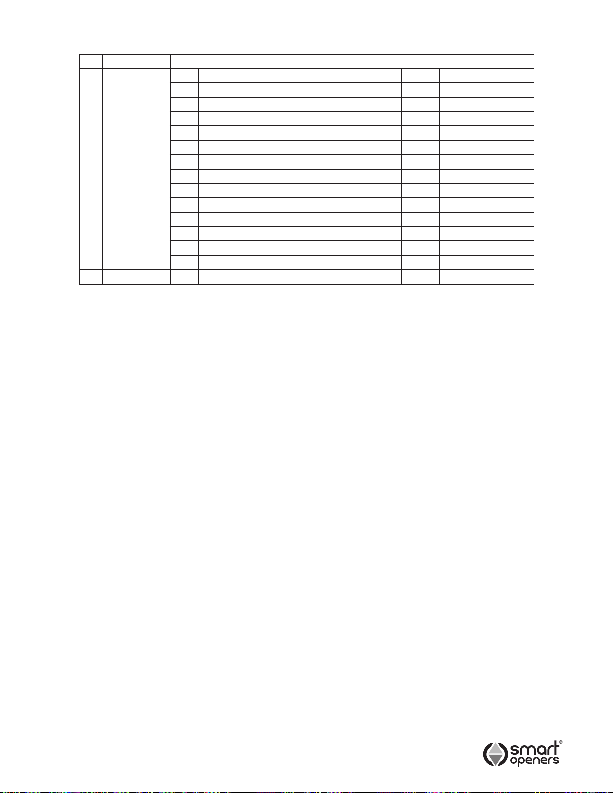
No Package Part
1 Motor No Description Qty Remark
1 Motor 1 Set
2 Transmitter 2 Pcs Transmitter
3 Remote Wall Switch 1 Pc
4 Remote Wall Switch Bracket 1 Pc
5 Disengagement Cord 1 Pc
6 Clutch 1 Pc
7 Bracket 1 Pc For Track
8 Bracket 1 Pc For Door Panel
9 Strapping 4 Pcs For Rail
10 Connector 2 Pcs For Door Panel
11 Bolts/Nuts 1 Set
12 Installation Manual 1 Pc
13 Owners Manual 1 Pc
2 Rail 1 Extrusion 1 Set
Contents
The Smart Lifter garage door opener requires a 240VAC
50Hz power input and has a 24V DC 100W motor and
can provide ‘Hold to Run’ control and automatic modes
for operation. When the door is in operation, movement
can be interrupted by activation of the safety inputs
(manual pull cord, transmitter, wall button (if tted) and
photo beams (if tted).
An encoder sets open and close positions and braking
during the end of the travel cycle reducing speed and
noise.
A 433.22MHz radio receiver is built into the circuit board
and the rolling code is memorised with the self-learning
technique. As an alternative to the built-in receiver the
unit will accept any of the range of stand alone radio
receivers. The unit has been designed to provide
maximum reliability, safety and exibility of use.
IMPORTANT:
Before starting to install the unit read all of the
instructions carefully and make sure you are familiar
with the safety warnings included in this manual and
in the OWNERS MANUAL.
Description
Page 4

-4-
Operating Controls
smart
openers
1 (UP button) Limit mode set.
2 (DOWN button) Reversing sensitivity set
3 (SET Button) Conrm set
4 (CODE Button) Transmitter code set
Circuit Board Connectors
5 Coupling for connecting the backup battery.
6 Coupling for connecting the motor.
7 Coupling for the power transformer.
8 Terminal for connection of power input, run lamp and
transformer.
9 Terminal connector to control board.
10 Terminal for connection of photo beam or push button.
5 6
7 8
9 10
1 3
2 4
Page 5
-5-
Installation
Remember there are specic standards that have to
be strictly followed regarding the safety of electrical
installations and automatic gates and doors.
As well as the legal requirements and standards that
must be adhered to, please take note of the following
points to ensure maximum safety and reliability of your
installation.
1.1) Prior to installing check the surrounding
environment. Carefully evaluate any hazards there
could be from physical damage (transiting vehicles,
parts of trees falling etc.), possible contact with
foreign bodies (insects, leaves, etc.), Flooding
hazards or any others exceptional events.
1.2) Check that the main voltage is the same as that
given on the rating plate and in this manual.
1.3) Check there is suitable electrical protection against
short circuits/power spikes and proper earthing on
the main supply.
Remember the unit has mains voltage running through it
(electrocution hazard, re hazard).
1.4) Take care with the control unit; parts may be
subject to damage if abused.
1.5) Make sure you have all the necessary materials
and that they are suitable for this kind of use.
1.6) Read all the instructions thoroughly and make sure
they are understood before attempting to install the
Smart Lifter.
1.7) Before starting the installation, carefully analyse all
the risks relating to automating the door. Verify that
the door to be automated is in a sound condition
and that the mechanisms are in good working
order; observe the safety margins and minimum
distances.
1.8) Evaluate with particular care the safety devices to
be installed and where to install them; always install
an emergency stop device for interruption of power
to the opener if required.
1.9) Once the risks have been analysed, install the
Smart Lifter opener and relative safety devices,
emergency stop and/or photoelectric cells.
Important: For additional safety Smart Openers Pty Ltd
strongly recommends the tting of Photo Electric safety
beams on all installations.
1.10) When installing the Smart Lifter opener, strictly
follow all the instructions given in the instruction
manual. If some points or procedures in this manual
are not very clear do not install the unit until all
doubts have been cleared up with our technical
department.
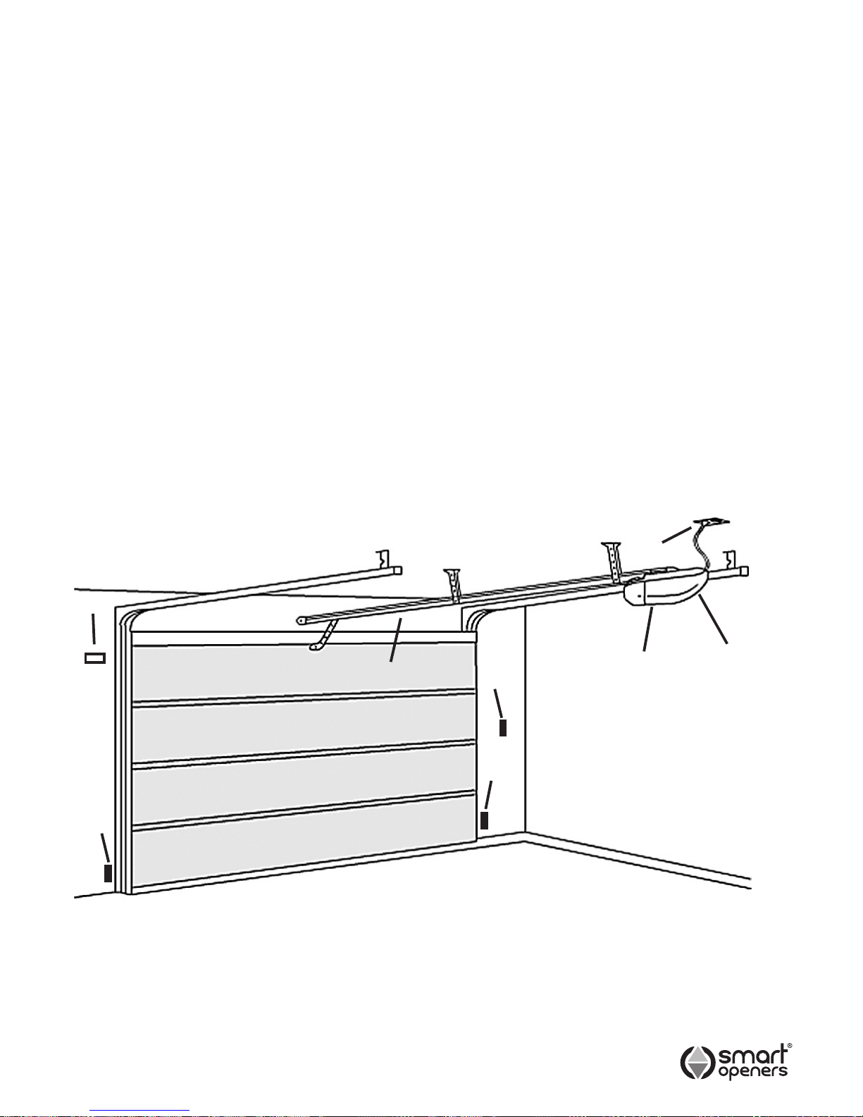
Refer to above for recommended installation
1) Smart Lifter sectional door opener
2) 24V DC ashing light (optional extra)
3) Key selector switch or digital keypad
4) Photo beam (RX/TX Type)
5) Inside push button panel
6) Power point
7) Power head
Fig. 1
1
2
3
4
4
5
6
7
Page 6
-6-
Installation
1). Read the instructions carefully.
2) Make sure the door structure is solid and suitable to
be motor driven.
3) Make sure that when the door is moving there are no
friction points.
4) The door must be properly balanced and must be
easily lowered and raised by hand.
5) Install a 240V, adequately protected 3-pin socket near
where the Smart Lifter opener is going to be installed
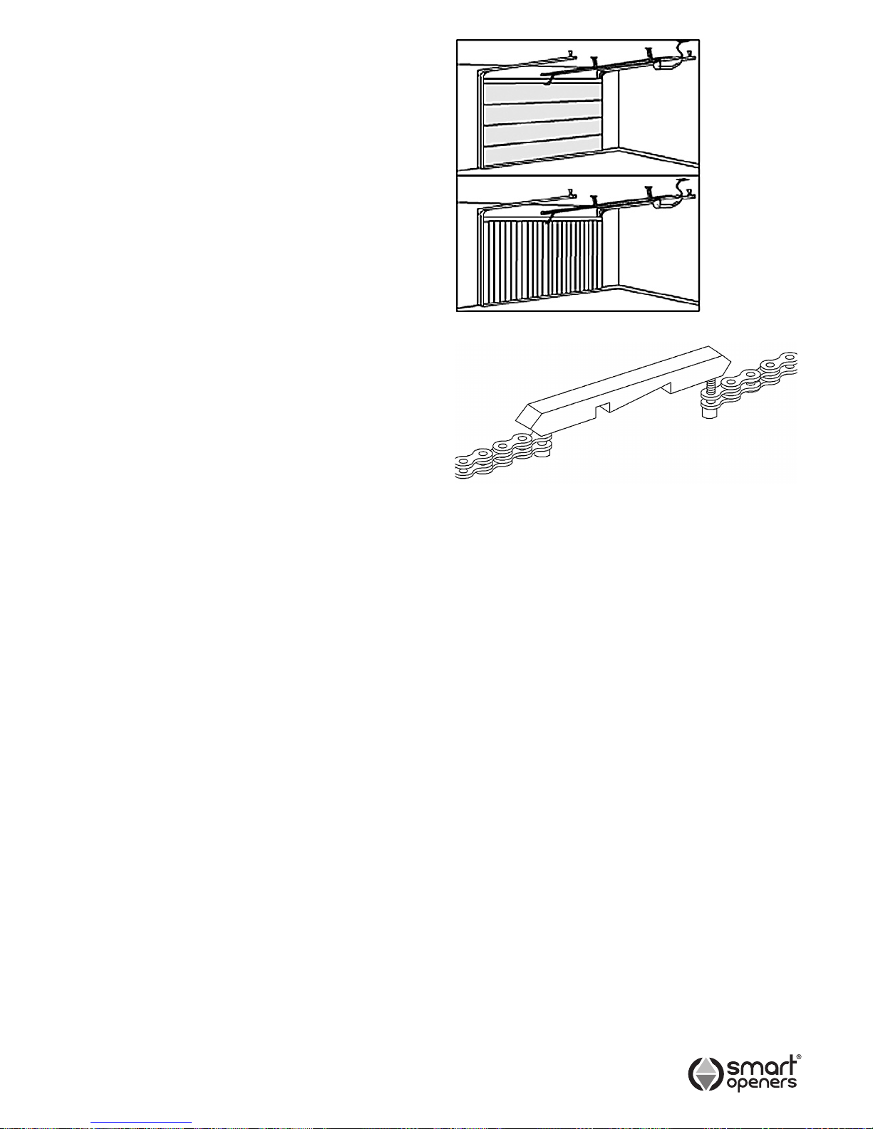
Sectional
Overhead Door
H max. 2600mm
Tilting
Overhead Door
H max. 2600mm
Fig. 3
Fig. 2
CHAIN SHUTTLE ASSEMBLY
For ease of installation the Smart Lifter is delivered with
the chain and chain index already assembled in the track.
If you need to assemble it yourself connect the chain
index to the chain refer (Fig. 3). Tighten screw (C) (Fig. 4
B) until the chain is reasonably tight. Do not over tighten,
but do not leave it too slack.
SHORTENING THE TRACK
The track is designed to be cut to size only if and when
required. This should only be done when space is at
a premium due to a lintel or some other obstruction.
Cut the track down to the desired size from the bracket
end only (not from the power head end). Remove the
appropriate amount of chain links with a chain breaker.
Reinstall chain in track and connect chain index as per
(Fig. 3) above. Tighten screw (c) (Fig. 4b) until the chain
is reasonably tight. Do not overtighten but do not leave it
too slack.
Page 7
F
E
D
-7-
Installation
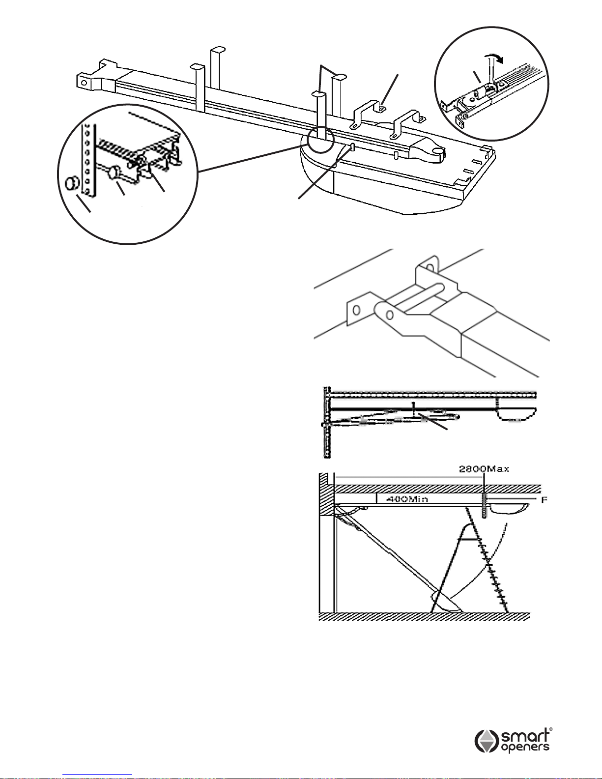
2.1) Insert shuttle into track by locating the cut out in
the bottom of the track at the powerhead end of the
track. It is important that the allen key bolt where
the arm connects onto the shuttle is facing the door.
Do not install it the wrong way round.
2.2) Move shuttle to half way along the rail section, grease
the chain and sprocket with a lithium type grease or
equivalent. Do not use oil based lubricants.
2.3) Place track onto powerhead so that the track
slides into spline shaft. Position the brackets (E)
on the studs and secure in place using ni-lock nuts
supplied. Lock the brackets to the rail by tightening
the ni-lock nuts. Do not over tighten the nuts.
2.4) Remove excess chain slack by tightening the chain
tightening screw (C) in (Fig. 4b) in a clockwise
direction (when viewed from the power head end of
the rail). Do not over tighten the chain, just enough
to remove the slack.
2.5) Fix the Smart Lifter opener to the lintel or to the
ceiling with the correct xing (Fig. 5), maintaining
a minimum gap of 30mm from the top panel’s
maximum height (Fig. 6). Check measurements
before drilling.
2.6) Insert the bolts supplied into the cutouts on both
sides of track at powerhead end. Slide bolts on
track to the correct hanging location to pick up
noggins or xing points. Place non ni-lock nuts onto
the bolt (ref Fig. 4c) and tighten. Place bracket (F)
onto bolt so that it sits against the nut and secure
with ni-lock nut supplied - do not over tighten.
Smart Openers recommend the tting of all four
straps on every installation.
2.7) Fix the Smart Lifter opener to the ceiling with
appropriate fasteners (Fig.7). Cut off any xing
strap excess.
Warning: Make sure the opener is afxed to noggins
in ceiling and not just to plasterboard. Failure to have
a safe and secure xing will lead to opener falling
causing serious personal and /or property damage.
Note: A set of xing straps should be located in the
centre of the aluminium rail to prevent rail ex that will
result in phantom reversing.
Fig. 4a
Fig. 5
Fig. 6
Fig. 7
C
Fig. 4b
30mm min.
2.8) Assemble straight arm and hockey stick using bolts
and nuts provided. Connect arms to door bracket
with pin and retainer clip and arms to shuttle on
opener with allen head bolt provided in shuttle.
Fig. 4c
NON
NI-LOCK
NUT
BOLT
NI-
LOCK
NUT
Page 8
-8-
Terminals and Connections
Programming the Unit
The system must be checked and tested when
connections are completed.
4.1) Check that the chain support is halfway so that
movement is problem free both in opening and
closing.
Make sure that all the standards relative to the
automatic gates and doors category have been
observed.
4.2) Now carry out a test with the door disconnected
from the motor and open and close the door to
verify that the mechanical parts are all in good
working order and the door does not bind or jamb
in its tracks.
4.3) Power the unit. As soon as the unit is powered the
system displays a 7-segment LED number from
0-9, and the lamp will turn on for 2 seconds.
If the LED display is upside-down, press the SET
button once, then the LED will display the number
in the correct direction. The system will remember
the display direction. It will display correctly next
time the power is turned back on.
If this is not the case, switch the power off
immediately and check connections carefully.
4.4) Check that all the safety devices on the unit are
working properly (emergency stop, photo beam,
etc.). This is one of the most important checks and
must be done with great care; in fact, the active
safety of the automatic door depends on the correct
functioning of the safety devices. The reversing
sensitivity device is of great help in minimising
damage but only the correct installation of the
safety devices will make it possible to stop the door
before it can cause any damage or injury to person
and/or property.
4.5) It is now time to set the opening and closed
position.
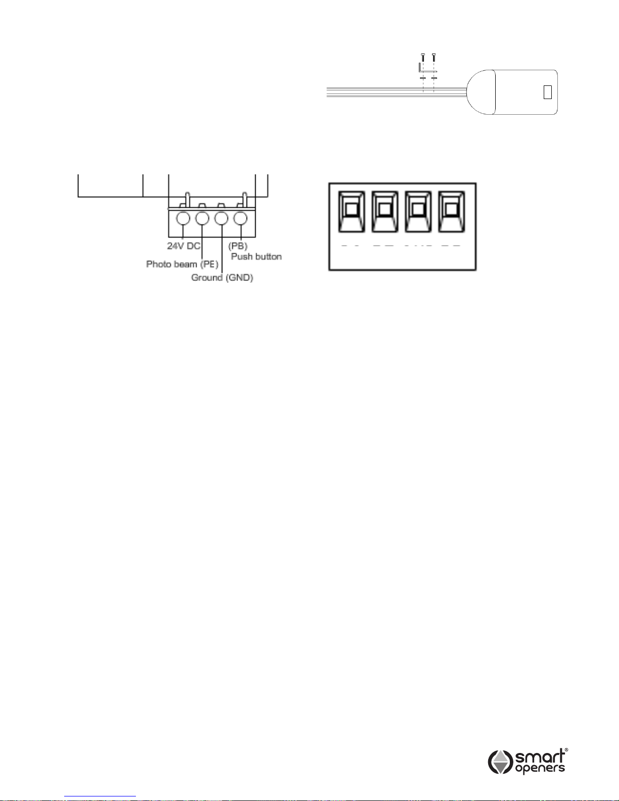
PB GND PE 24
1) GND & PB: Step by step command input (open
stop close) same as the step by step button on the
transmitter. = Push Button terminal
2) GND & PE = Photo Beam terminal.
3) 24V & GND & PB = Plug in receiver terminal.
To safeguard the opener and avoid damaging
components while wiring disconnect the unit from all
power when working on it.
Remember that there are specic, strict standards that
must be complied with in regard to both the safety of the
electrical systems and automatic doors.
Only qualied, trained personnel may carry out the
installation and subsequent maintenance in compliance
with Australian standards.
Whoever installs and uses the Smart Lifter sectional door
opener will be held responsible for any damage caused.
NOTE: Contact Smart Openers technical department for
the wiring diagram for the above connections if uncertain
of the correct procedure.
Shuttle Stop
3.1) Fit the shuttle stop to the track at the power head
end by inserting the stop assembly into the track
and tighteneing the bolts .Do not overtighten.(Fig 8)
This will prevent the door from contacting the motor
when operatated manually.Warranty will be void if
motor is damaged due to stop not being tted.
Fig. 8
Page 9
-9-
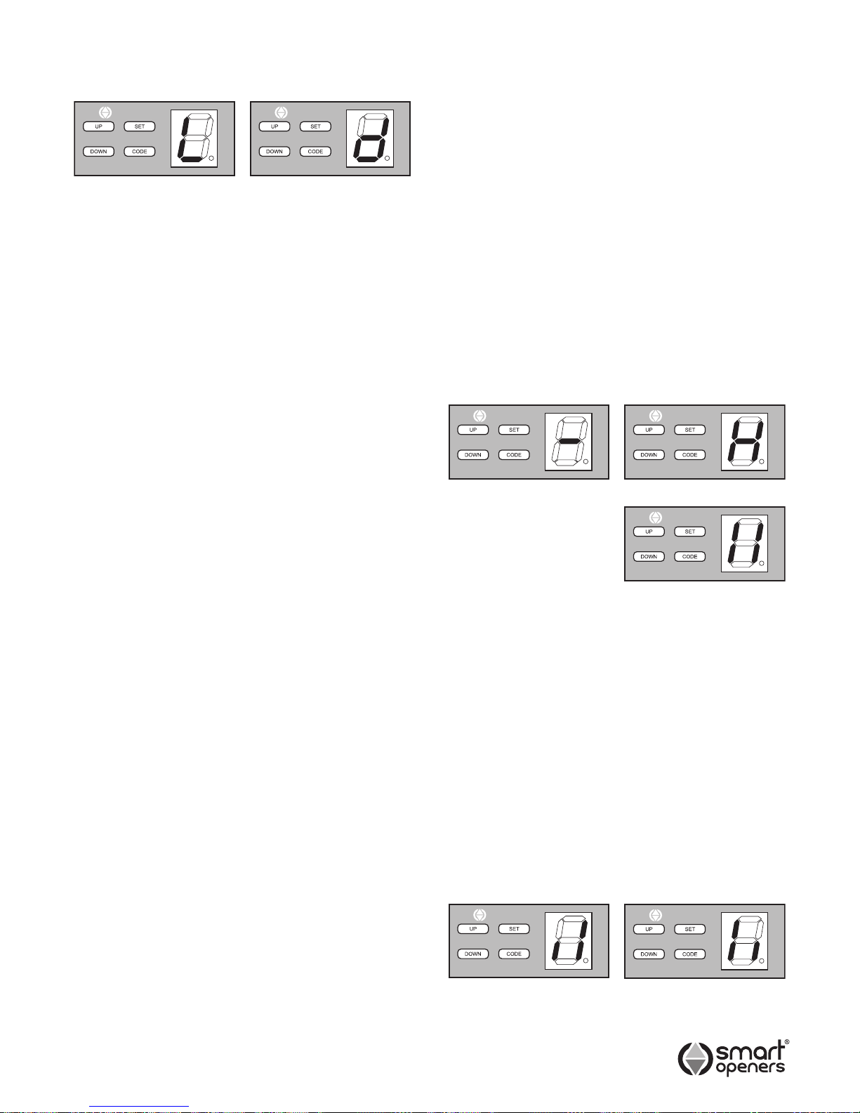
5.1) Press and hold UP until the LED displays the letter
L release UP.
5.2) Now press UP again and hold, the door will travel to
the open position, release the button when the door
has reached the desired position.
5.3) If the door has overrun its position, press DOWN to
move the door downwards. Adjust and ne tune the
position by pressing UP and DOWN.
5.4) Press SET to set the open position the LED will
display the letter d it is now time to set the closed
position.
5.5) Press and hold DOWN, the door will travel to the
close position release DOWN when the door has
reach the closed position.
5.6) If the door has overrun its position, press the UP to
move the door upwards. Adjust and ne tune the
position by pressing DOWN and UP.
5.7) Press the SET to conrm.
The door will now open and close automatically to map
the open and close sensitivity force requirements.
WARNING: Keep all persons and property clear of door
during the installation process.
5.8) The door is now set for normal operational mode.
IMPORTANT: Safety systems must be checked
regularly to ensure that maximum safety is
maintained at all times.
Note: If you are not happy with the limits setting. Go back
to Step 5.1 to set new limits.
Adjustments
Normally, the force settings are automatically set and
adjustment is not necessary. However, the force can be
adjusted by an authorized smart opener’s installer for
special purposes if necessary.
6.1) Press DOWN and hold, the LED will display a
setting number from 1 to 9, release DOWN, it is
now in force adjustment mode.
6.2) Press UP to increase the force one-degree and
press DOWN to decrease one degree maximum
degree is 9 and the minimum is 1.
6.3) Press SET to conrm.
Setting Open and Close
Positions
Function Modes
The Smart Lifter has two selectable functioning modes:
PHOTO BEAM and AUTO-CLOSE. Photo Beam mode
should only be actived when a photo beam is connected.
The opener will not function correctly if a photo beam is
not connected.
Note: For safety Auto-Close should only be activated
when a photo beam is installed.
7.1) SET PHOTO BEAM
Make sure the photo beam has been installed correctly
before setting the PHOTO BEAM function.
7.1.1) Press and hold DOWN and SET until the LED
displays –.
7.1.2) Press DOWN once, the LED displays H, the photo
beam is now enabled.
7.1.3) Press SET to conrm.
To disable photo beam enter function mode set as above.
Press DOWN so that the LED displays ||. Press SET to
conrm.
7.2) SET AUTO-CLOSE
7.2.1) Press and hold DOWN and SET until the LED
displays –.
7.2.2) Press UP once, a full vertical line on right and
half-vertical line on the left will be displayed II,
auto-close is enabled. See 7.2.3 to set time delay.
7.2.3) Press DOWN once, to increase the auto close
time by 1-minute increments from 1 – 9, once
you get to 9 it will go back to 1.
7.2.4) LED displays the current set value.
7.3,3) Press SET to conrm.
To disable Auto-Close enter mode set as above. Press
UP once, a full vertical line on the left and a half-vertical
line on the right will be displayed (II), auto-close has been
disabled. Press SET to conrm.
smart
openers
smart
openers
smart
openers
smart
openers
smart
openers
LIMITS SET MODE LIMITS SET DOWN
FUNCTION MODE SET
smart
openers
PHOTO BEAM ACTIVE
smart
openers
PHOTO BEAM DISABLED
AUTO-CLOSE ACTIVE AUTO-CLOSE DISABLED
Page 10
-10-
Note: This Smart Lifter opener is supplied with the
transmitters already coded (depending on country).
Please test all transmitters to conrm that they are coded
prior to starting Step 8.1.
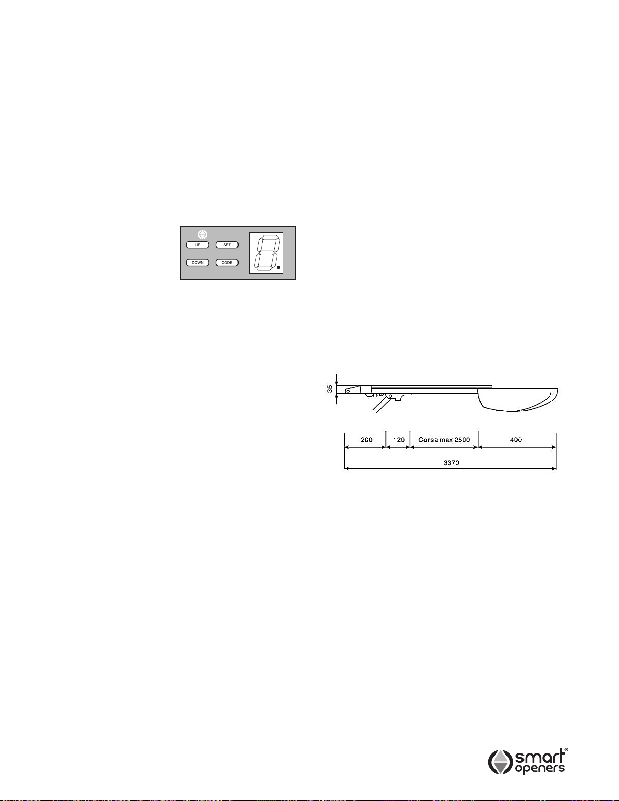
8.1) Press CODE until the LED displays (.). Press a
button on the transmitter, the LED dot will turn off.
Release and press the same button again, the dot
will ash to conrm the code.
8.2) Repeat step 8.1 to code a maximum of 20 different
transmitters and/or buttons.
8.3) To delete all stored codes, press and hold CODE
for 8 seconds until LED dot turns off, all stored
codes have now been deleted.
Maintenance
No particular maintenance is required for the logic circuit
board.
At least twice a year check that the door is properly
balanced and that all working parts are in good working
condition.
IMPORTANT: A poorly operating door can effect the life of
the automatic opener due to incorrect loads and will void
the warranty.
Check the reversing sensitivity at least twice a year and
adjust if necessary.
Make sure that the safety devices are working effectively
(photo beams, etc.)
Final Notes
This manual is only for use by technical personnel
qualied to carry out the installation.
No information given in this manual can be considered of
any interest to the end user.
No setting or adjustments contained in this manual
should be carried out by the end user.
It is important for the installer to show their clients correct
operational use of the Smart Lifter including the use of
the manual disengagement cord.
Inform the owner about the need for regular and accurate
maintenance, especially regarding a regular check of the
safety and reversing devices.
Coding Transmitters Technical Specications
Power Input: 240 VAC ±10% 50Hz
Motor: 24V DC 100W
Courtesy light time: 3 mins
Working temperature: -20° ~ 70°C
Relative Humidity: <90%
Open and close force: 600N
Reception frequency: 433.22MHz
Sensitivity: >1V for correct receiver signal
(average range 50m, with an
aerial)
Decoding: Rolling code
Transmitter power: 23A 12V Battery
Globe: 24V 21W Automotive type
(availalble from most car
accessories stockists)
NOTE: Smart Openers Pty Ltd reserves the right to
modify its product and product specications at any
time without prior notice.
Typical Application
The Smart Lifter (max. 2500mm travel) model can
automate sectional overhead doors up to a height of
2600mm and tilting overhead doors up to 2600mm.
smart
openers
TX CODE ACTIVE
Page 11
-11-
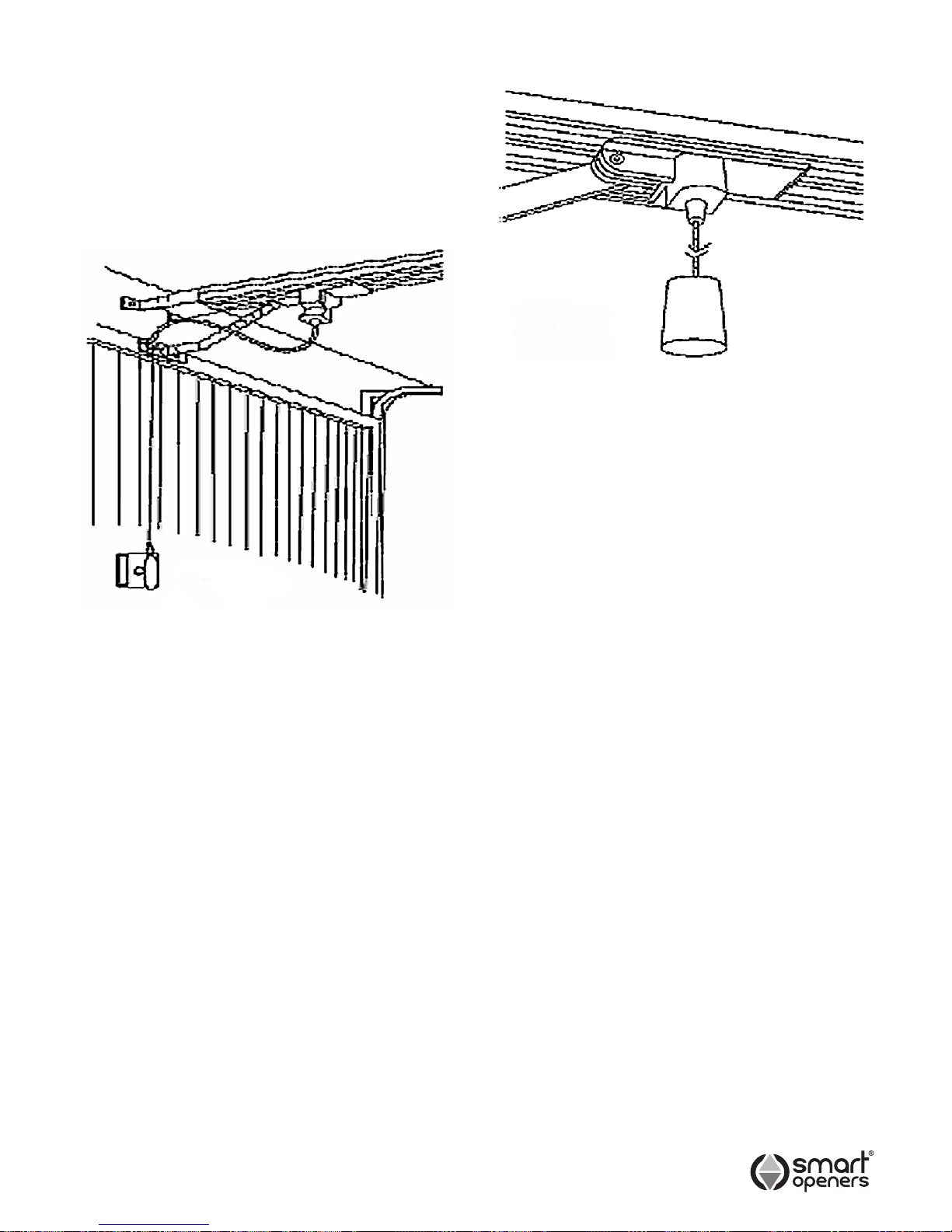
The Smart Lifter is equipped with a manual release
cord to disengage shuttle and move door by hand while
holding the handle down (Fig. 9). To operate pull on the
handle to disengage the shuttle. To re-engage the door
simply run opener in automatic mode or move door by
hand until the trolley engages in the chain shuttle.
For situations where a pedestrian door is not present it is
recommended that an external disengagment device is
tted. (Fig. 10).
Manual Disengagement
Fig. 9
Fig. 10
Important Information for
the User
Once the Smart Lifter opener has been installed, the
user must be informed about how it works and all the
risks that can arise if it is used improperly. The user must
avoid placing himself/herself in dangerous situations such
as standing within the door’s operating range when it is
moving.
Do not let children play near the door and keep the
remote controls out of their reach.
All servicing, repairs or checks must be carried out
by professionally qualied personnel and noted on a
maintenance register kept by the user.
Information for the user is found in the USERS/OWNERS
MANUAL included with this opener.
IMPORTANT: Please make sure the USERS/OWNERS
MANUAL is passed on the the owner prior to leaving the
installation.
IMPORTANT: In the case of a malfunction the user must
call an authorized smart opener Pty Ltd installer and
should not attempt to repair it.
Page 12

© October 2009 Smart Openers Pty Ltd. All rights reserved. In an ongoing commitment to product quality and innovation smart openers reserves the
right to change and alter specications and model numbers and types without notice
D/N: SLIM141009
Smart Openers Pty Ltd
PO Box 6666 GCMC, Qld 9726
Tel: 1300 366 547 Fax: 1300 366 972
Email: [email protected]
Web: www.smartopeners.com
Warranty and Exclusion of Liability
1. This warranty is an addition to any conditions or warranties that are implied by relevant statute, including the Trade Practices Act 1974 (Cth),
which cannot be excluded or negated.
2. Subject to all of the matters set out below, Smart Openers Pty Ltd (“Smart Openers”) warrants:
(a) swing and sliding gate opener drive units for twelve (12) months
(b) roll-up and overhead door opener drive units for twenty four (24) months
(c) all components and accessories for twelve (12) months,
from the date of purchase (specied in the sales docket receipt) as free of any defects in material and workmanship.
3. This warranty applies only where the purchaser:
(a) immediately noties Smart Openers or the retailer of the alleged defect;
(b) returns the product to Smart Openers or the retailer; and
(c) presents the relevant sales docket and this warranty document to the retailer and, if so requires, to Smart Openers to conrm the
date of purchase.
4. Defects or damage partly or wholly due to any of the following causes are not covered by this warranty:
(a) accidental damage to any of the Product or to the Product’s components;
(b) normal wear and tear to the Product or to the Product’s components;
(c) ood, rain, water, re, lightning , storms, any acts of God, contamination or pollution;
(d) incorrect, improper, inappropriate or unreasonable maintenance and/or use;
(e) installation, adjustment or use which is not in accordance with the instructions set out in installation instructions incorporated in the
document;
(f) attempted or complete modication or repairs to the Product or tampering with the Product carried out by a person who is not
authorised by Smart Openers to carry out such modication or repairs;
(g) faulty or unsuitable wiring of structure to which the Product is xed or connected;
(h) radio (including citizen band transmission) or any electronic interference;
(i) blown fuses or damage caused by electrical surges, power surges or power spikes;
(j) damage caused by insects or any infestation;
(k) negligence or deliberate damage.
5. Except for this warranty, Smart Openers gives no warranties of any kind whatsoever (whether express or implied), in relation to the product,
and all warranties of whatsoever kind relating to the product are, to the extent permissible by statute, hereby excluded and negated.
6. To the extent permissible by statute, Smart Openers disclaims any liability of whatsoever nature in respect of any claim or demand for loss or
damage which arises out of:
(a) accidental or deliberate damage to, or normal wear and tear to, the product or to the product’s components;
(b) any cost relating to damage resulting from wear and tear;
(c) blown fuses, loss or damage caused by electrical surges, power surges or power spikes;
(d) loss or damage due to theft, re, ood, rain, water, lightning, storms, any acts of God, contamination or pollution;
(e) door or gate not in safe and correct working order and condition;
(f) evidence of unauthorised repairs;
(g) any cost relating to damage caused deliberately or by misuse, negligence or failure to maintain the equipment in a proper working
order, including (without limitation) due to anything described in paragraphs (d) and (e);
(h) installation, adjustment or use which is not in accordance with the instructions set out in installation instruction manual and owners
manual;
(i) attempted or complete modication or repairs to the Product or tampering with the Product carried out by a person who is not
authorised or has not been trained by Smart Openers to carry out such modication or repairs;
(j) faulty or unsuitable wiring of structure to which the Product is xed or connected;
(k) radio (including citizen band transmission) or any electrical interference;
(l) damage caused by insects or any infestation;
(m) loss or damage to any property whatsoever or any loss, damage or expense whatsoever resulting or arising therefrom;
(n) any consequential, indirect, special or incidental loss or damage;
(o) any cost or expense arising due to manufacturer recall of any product;
(p) any cost or expense due to negligence of the approved service provider;
(q) installation of a residential garage door or gate opener in a commercial or industrial situation or a non-single residential dwelling.
7. Smart Openers liability under this warranty is limited, at Smart Openers absolute option, to replacing or repairing the product which Smart
Openers, in its unfettered and absolute opinion, considers to be defective either in material and/or workmanship or to credit the dealer with
the price at which the product was purchased by the dealer.
8. This warranty does not extend to cover labour for installation.
9. This warranty is limited to Return-to-Base (RTB) repair and does not cover labour for on-site attendance.
10. This warranty is void if the Product is not returned to the manufacturer in original or suitably secure packaging.
11. This warranty is only applicable for repairs to the Product carried out within Australia and for Product in Australia.
12. This warranty does not cover consumable items including globes, batteries and fuses.
13. This warranty is not transferable.
14. Where the Product is retailed by any person other than Smart Openers, except for the warranty set out above, such person has no authority
from Smart Openers to given any warranty or guarantee on Smart Openers behalf in addition to the warranty set out above.
Notes:
1. This warranty is to be read in conjunction with the installation manual and owner’s manual.
 Loading...