


User Manual

User Manual
Congratulations for purchasing a SmartMotion electric bicycle!
Please read this guide fully BEFORE using your electric bike.
Contents
1. Contents of shipping carton
2. Assembly instructions
3. Safe Riding Recommendations
4. Maintenance & Adjustment
5. Frame Lock and Seat
6. Main Specifications
7. Do’s and Don’ts
8. Display Panel Controls
9. Battery instructions
10. Warranty
11. Service Checklist
12. Service Record
In the Essence box you will find the following items:In the Vista box you will find the following items:
1. SmartMotion electric bicycle
2. Battery charger
3. Bottle cage
4. 2X Pedals
5. Tool kit (4mm, 5mm & 6mm allen key,
8mm/10mm spanner, 15mm spanner)
6. 2X keys for frame lock and battery lock
7. Front light
8. Elastic strap
1. SmartMotion electric bicycle
2. Battery charger
3. Bottle cage
4. 2X Pedals
5. Tool kit (4mm, 5mm & 6mm allen key,
8mm/10mm spanner, 15mm spanner)
6. 2X keys for battery lock
7. Elastic strap
1. Content of Shipping Carton
To Prepare
We recommend that you familiarise yourself
with the bike parts before assembling. Gather all
required tools. Be sure to work in a clean, dry space
with plenty of room. You might wish to lay down a
tarpaulin or old blanket to protect the bike during
assembly. You may find it helpful to stand the bike
frame on a block or sturdy box under the battery
housing to work with it in an upright position.
Please watch the balance when installing wheels.
1. Unpack
a. Carefully lift the electric bike out from the carton
(two people recommended for this task). Cut the
nylon zip ties with suitable scissors and remove the
foam protection from the bike.
b. Unfold the main frame until the hinge joint is fully
closed and lock it by pushing alloy lock lever until
it clamps against the frame. Then rotate the plastic
secondary lock down into the alloy lock lever.
The Vista electric bike is shipped folded inside the
carton and 95% assembled. Follow these steps to get it
ready and safe for you to ride.
2. Assembly Instructions
Vista
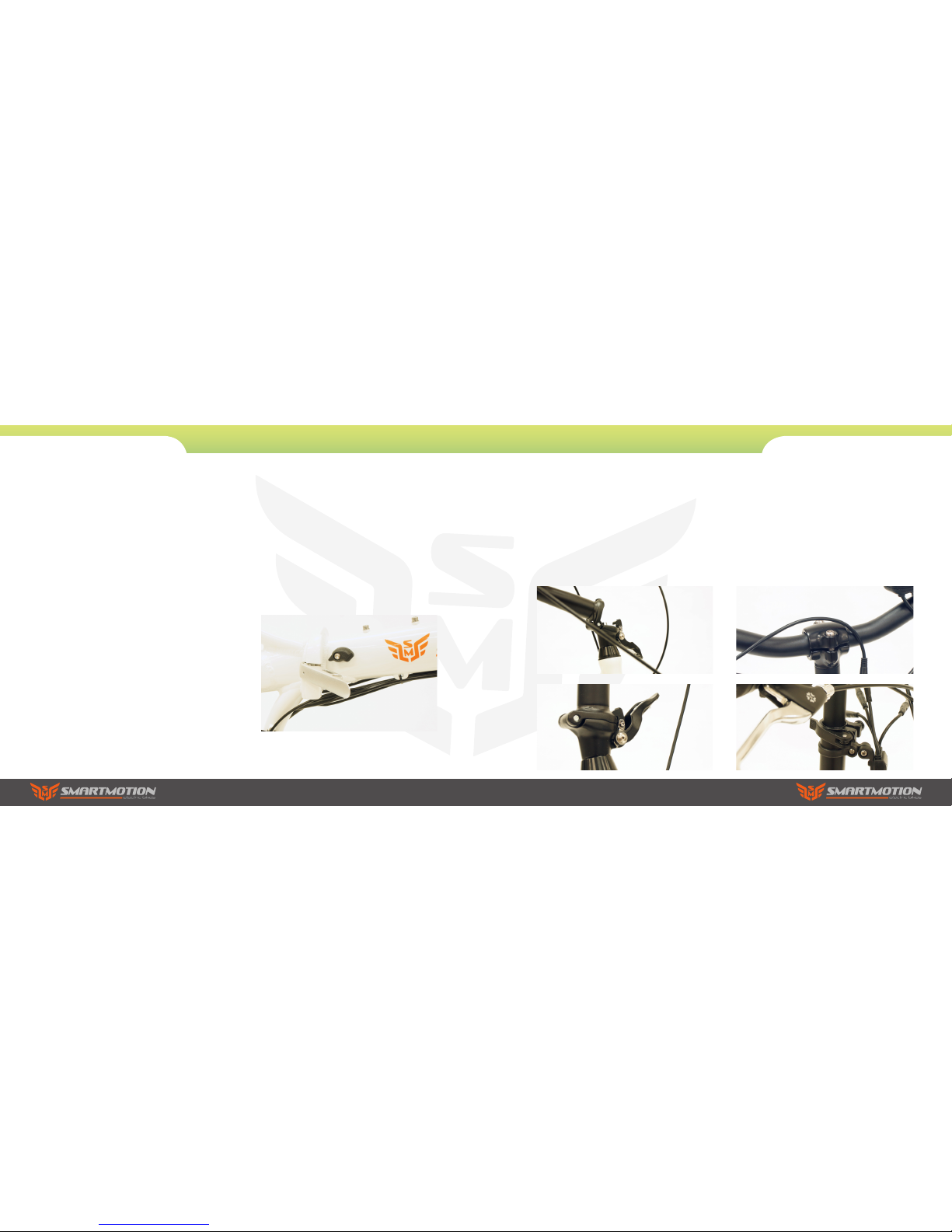
2. Handlebars
a. Carefully unfold the handlebar stem post up into
its vertical position, then close the alloy lock lever
against the stem post. The lock lever will be locked
automatically.
b. Adjust the handlebar horizontal rotation if
needed loosening the handlebar stem bolts, then
twist the handle bar to the correct angle and then
tighten back up.
Adjust the vertical height of handlebar opening the
quick release lever out on the mid section of the
stem post, then when adjusted tighten back up by
pushing the lever in.
2. Assembly Instructions
Vista
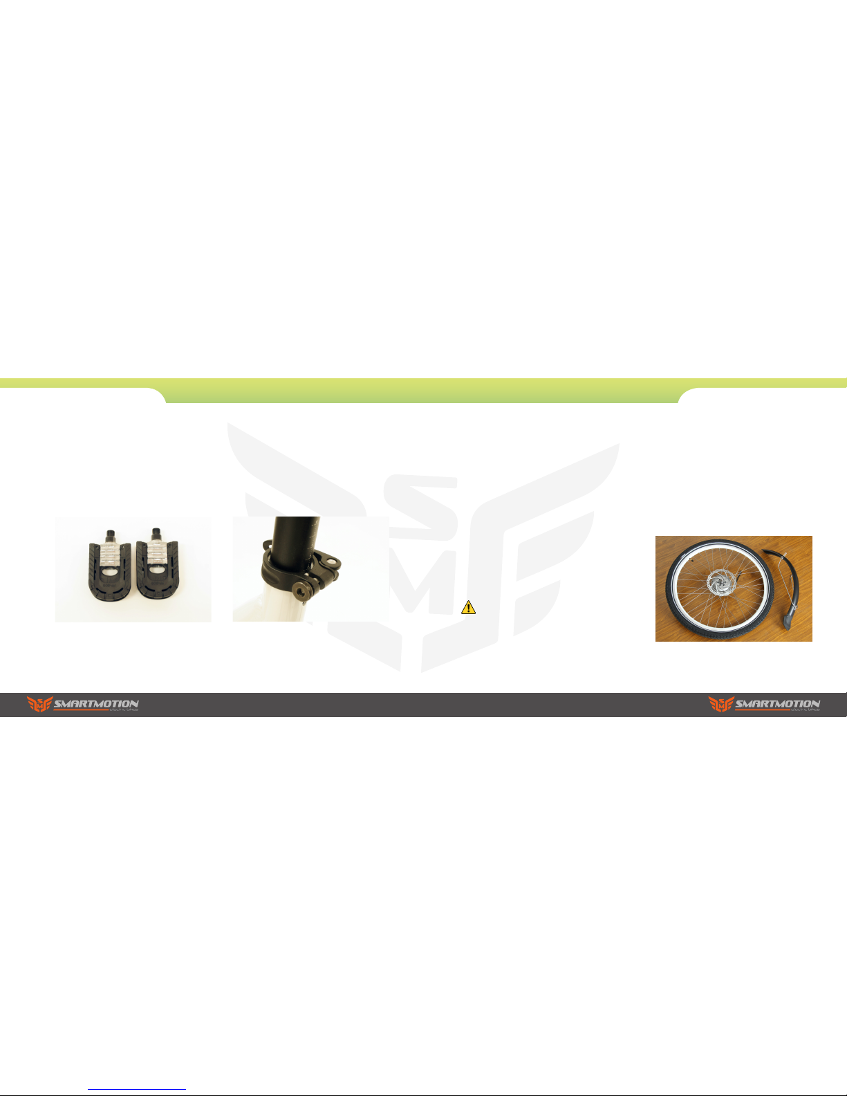
4. Seat
Release the seat post clamp lever and set the seat
post height to the position which is suitable for
you to comfortably reach the ground when you
are sitting on the bike, then refasten the seat post
clamp. The maximum height should be within the
max height markings on the seatpost.
3. Pedals
Attach the foldable pedals to the cranks, paying
attention to the “L” or “R” marked on the pedal
axles. Screw in the L pedal counterclockwise and
the right pedal clockwise.
2. Assembly Instructions
Vista
To Prepare
We recommend that you familiarise yourself
with the bike parts before assembling. Gather all
required tools. Be sure to work in a clean, dry space
with plenty of room. You might wish to lay down a
tarpaulin or old blanket to protect the bike during
assembly. You may find it helpful to stand the bike
frame on a block or sturdy box under the battery
housing to work with it in an upright position.
Please watch the balance when installing wheels.
1. Unpack
a. Carefully lift the electric bike out from the carton
(two people recommended for this task). Cut the
nylon zip ties with suitable scissors and remove the
foam protection from the bike.
b. Remove the front wheel and mudguard from the
bike and put them aside. Carefully stand the bike
upright, resting on its forks when installing wheels.
Your electric bike is shipped 85% assembled. Follow
these steps to get it ready and safe for you to ride.
2. Assembly Instructions
Do not activate the brakes until the bike is
fully assembled. Squeezing brake levers
while calipers have no disc rotor between
them can damage the brakes.
Essence
2. Fork
a. 3. Insert the handle bar stem into the steering
tube, turn it to align it with the forks correctly, then
fasten the centre screw using the 5mm allen key to
18-20N.M. This is a quill type stem that if set too
high can cause damage to your bicycle, decrease
your control and cause you to fall. Make sure the
Minimum-insertion mark is within the frame.
b. Loosen the handle bar angle adjusting bolt
(at the pivot point of your adjustable stem) two
or three turns then adjust the stem angle to the
position comfortable for you. Then loosen the 2
handlebar clamp bolts and rotate the handlebar to
make sure the brake lever and lcd display positions
are at the correct angle, then fasten the two bolts to
17-20N.M. Finally fasten the angle adjusting bolt to
17-20N.M
2. Assembly Instructions
Essence
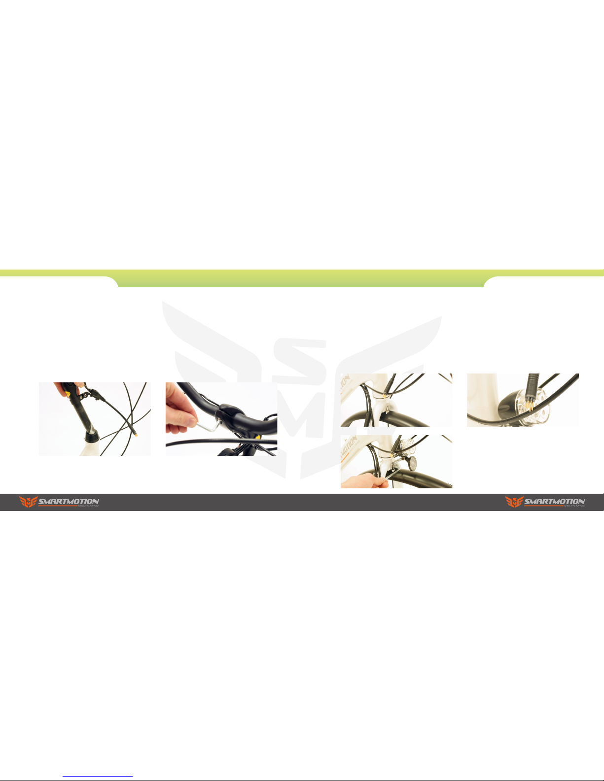
3. Mudguard
Install the front mudguard and front reflector on
the fork. Take off the bolt from the front fork, put
the front reflector bracket on the outside of the
fork then put the front mudguard bracket on. Put
the bolt through the fork, then fasten the bolt
with a 5mm allen key and 10mm spanner. Then
fasten the two mudguard stays to the forks.
4. Power Connection
Finally connect the main cable exciting the frame
near the headtube to the handlebar components
cable, making sure the arrows align before pushing
the connectors together.
2. Assembly Instructions
Essence
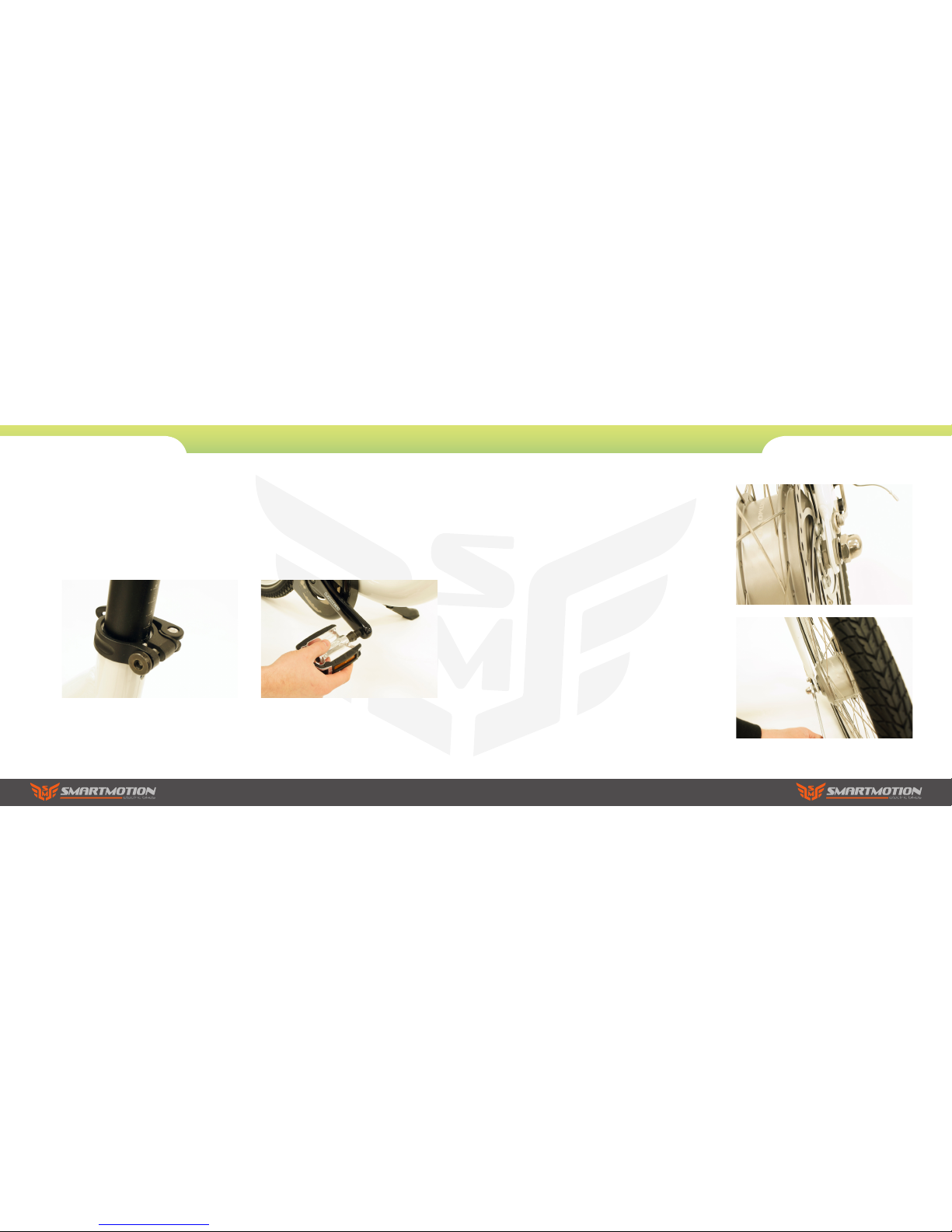
5. Seat
Release the seat post clamp lever and set the
seat post height to the position which is suitable
for you to comfortably reach the ground when you
are sitting on the bike, then refasten the seat post
clamp. The maximum height should be within the
max height markings on the seatpost.
6. Pedals
Attach the pedals to the cranks, paying attention
to the “L” or “R” marked on the pedal axles. Note:
the pedals have opposing threads – screw in the left
pedal counterclockwise and screw in the right pedal
clockwise. Install L pedal counterclockwise and the
right pedal clockwise.
2. Assembly Instructions
Essence
7. Front wheel
Carefully insert the front wheel axle into the front
fork dropout, guiding the disc rotor in between the
disc brake calipers as you do so. Note: you may
prefer to position the bike upside down for this
procedure – but be careful to stabilise the bike if
you do so. Important: make sure the anti-turning
washers are positioned between the motor washer
and the inner side of the fork. Please refer to the
adjacent pictures. Once the axle is fully inserted
and resting on the tops of the dropout (wheel
is correctly aligned inside forks) use the 15mm
spanner to fasten the nut to 70N.M
Important: you must recheck the torque setting
of the motor axle nuts after the first week of use,
then every 3 months after that to ensure correct
tightness. If loose, the motor axle can spin and
break the dropout and cause serious injury.
2. Assembly Instructions
Essence

1. Please observe traffic regulations, and don’t lend your
bicycle to anyone who is unfamiliar with it. The bicycle can
legally only be used on the road by a person aged 14 years or
over.
2. If you are in a country where wearing a cycle helmet is not
compulsory, we still strongly advise you to always wear one.
If you are unfamiliar with cycling, we also advise you to attend
a cycle proficiency course prior to using it, or gain advice from
your local SmartMotion dealer. Your eUrban is not a toy and
should be considered a serious mode of transport.
3. As with all bicycles it is important that you stay within safe
limits. If you feel you are traveling too quickly for the road
conditions you probably are, so slow down! High speed will
increase forces in the case of an accident and increase the
possibility of injury.
4. Test your brakes prior to using the bike every time you use
it and remember the bike will not stop as quickly in wet or icy
conditions as it would on a dry road.
5. Check the tyres, rims, pedals, stem, cables, chain, etc for
general condition regularly.
6. A rider is very difficult for motorists and pedestrians to see
at dusk, at night, or at other times of poor visibility. If you must
ride under these conditions, check and be sure you comply
with all local laws about night riding; follow the rules of the
road. Take the following additional precautions: make sure that
your bicycle is equipped with correctly positioned and securely
mounted reflectors, wear light-colored, reflective clothing
and or accessories (any reflective device or light source that
moves will help you get the attention of approaching motorists,
pedestrians and other traffic). Make sure your clothing or
anything else you are carrying on your bicycle doesn’t obstruct
a reflector or light. Ride slowly when conditions demand you to
do so.
7. Check the front and rear rim’s safety line. Replace wheel
when any part of the Rim Wear Groove is not visible. It is
dangerous not to do so.
8. If a rear child seat is fitted, before putting your child in, read
the full safety instructions of the seat manual to check seat is
installed correctly and child is fastened properly.
9. You must not leave the bike unattended or use the kickstand
to stand the bike without your support when a child is in the
rear seat as the bike could tip over and cause serious injury.
10. Make sure the rear suspension underside of your seat is out
of reach of your child to avoid finger injury.
11. Your bicycle must be returned to your servicing dealer
or bicycle/motorcycle mechanic after one month or 200km
of riding (which ever comes first) to re-tension the spokes.
Then every six months or 1000km (which ever comes first)
for a general service and thorough inspection. Failure to do
this can void your warranty due to unnecessary wear .
3. Safe Riding Recommendations
Pre-ride Checklist
Please make sure the brake lever sequence is
correct for your country before riding. In UK, NZ
and Australia the left brake lever is for rear brake
and the right brake is for the front brake. In all
other countries it is the other way: left for front,
right for rear.
Check the tyres for any visible damage.
Check tyre pressures are 40-60psi, and adjust if
necessary.
Check for any loose nuts, bolts, or fixings.
Check brake functions, cable tension, pad
clearance, etc.
Check all electronic functions are ok (functions
detailed later in this manual).
Check the reflectors are in place and the lights are
working (detailed later in manual).
Torque Settings
Check bolts are tightened according to the following
recommendations before you set off for the first time.
a. Seat pillar clamp nut/bolt 5N.M-8N.M
b. Brake cable anchor bolt 5N.M
c. Brake centre bolt 11N.M
d. Seat angle clamp bolt 24N.M
e. Crank axle nuts R:42N.M
L: 46N.M
f. Gear shifter nuts 4N.M
g. Rear carrier nuts 8N.M
h. Mudguard bracket nuts 8N.M
i. Handle bar clamp nut 17-20N.M
j. Quill stem bolt 19N.M
k. Seat tube clamp nut 4-7N.M
l. Rear wheel axle nuts 40-45N.M
m. Quick release front axle. Measured torque
not typically used. Common industry practice is
resistance at lever half way through swing from
open to fully closed.
For all other nuts, the torque depends on the nut
diameter: M4 2.5-4.0N.M
M5 4.0-6.0N.M
M6 6.0-7.5N.M
Note: make sure axle nuts are always done up tight
on both wheels as connections to the motor and the
dropouts can be damaged due to the axle spinning.
3. Safe Riding Recommendations

4. Maintenance & Adjustment
1. Gear Adjustment
Shimano’s 3-speed internal hub is a device that
allows the rider of the bike to change gears without
the worry of chain tension and derailleur setup and
maintenance. The hub can even switch gears when
the pedals are stationary. However, without being
adjusted properly, the Shimano 3-speed internal
hub will not work correctly, shifting between gears
and sometimes not allowing the bike to move at all.
Learn how to adjust your Shimano 3-speed hub at
home, and save time and money over taking your
bike to the local bike shop to be serviced.
1.1 Set your bike on its kickstand or in a dedicated
bicycle work stand so that it will not fall over while
you are working. You should be able to spin the rear
wheel freely to perform this procedure.
1.2 Twist the handlebar gear shifter to shift into
second gear, or the middle gear of the hub. Inspect
the rear wheel axle, where the gear shift cable
meets the push-rod housing. The housing should
have a clear plastic window with two red or white
lines marked on it, and a red indicator inside the
plastic. When the hub is adjusted properly, this red
marker will be in the center of the two markings in
second gear.
1.3 If adjustment is needed, loosen the cable
adjuster lock-nut on the cable where it enters the
hub using an 8-millimeter wrench. If the indicator
sits too far to the right between the markings,
tighten the cable adjuster until it is aligned
between them. If the indicator sits too far to the left
between the markings, loosen the cable adjuster
until it is aligned.
1.4 Tighten the cable adjuster lock-nut using an
8-millimeter wrench, then take your bike out for a
test ride. The hub should not skip, shift randomly,
or cease spinning for any reason. If these symptoms
still persist, the bike should be looked over by a
certified mechanic.
4. Cleaning your electric bike
Warm soapy water and a cloth can be used to clean
the frame of your bike, but care must be taken not
to immerse any of the electrical components; they
are rainproof but cannot be immersed in water. The
motor can be cleaned with a soapy cloth, but also
must not be immersed in water. The battery can be
cleaned with a damp cloth, then dried afterwards.
Note: in salty conditions it is essential to clean and
lube your bike regularly.
4. Maintenance & Adjustment
2. Chain Adjustment
Your bike has a gear hub that will not need to
tension your chain. However if the chain becomes
loose (more than 20mm of movement possible in
centre of chain between rear axle and crank axle) or
frequently comes off the drive wheel, you can easily
adjust the chain tension by loosening the rear axle
nuts slightly, and adjusting the hub axle backwards
further to tighten the chain tension to about 10mm
of movement in centre. Re-tighten the axle nuts to
correct torque setting.
3. Lubrication
1.1 Once a month lubricate all pivot points
on your derailleur and the derailleur pulleys with
suitable chain lube.
1.2 Every three months lubricate the brake
lever pivots, gears and chain with suitable oil.

5. Other Maintenance
Your bicycle must be returned to your servicing
dealer or bicycle/motorcycle mechanic after one
month or 200km of riding (which ever comes first)
to re-tension the spokes. Then every six months
or 1000km (which ever comes first) for a general
service and thorough inspection. Failure to do this
can void your warranty due to unnecessary wear
and tear.
Excluding the electric drive side of things, your
SmartMotion bicycle is a normal bicycle, with
normal components. Your dealer will be able to
explain to you the general care and maintenance of
the normal bicycle components. You should pop
your bike in for a check-up after about a month’s
use as new gear and brake cables will stretch, then
every 6 months after that.
The electric drive system is maintenance free and
has self-diagnostic codes that will be displayed on
the LCD console (detailed later in this user guide)
should anything go wrong. Again, speak to your
dealer should any issues arise.
4. Maintenance & Adjustment
Frame Lock- Essence only
The SmartMotion Essence has been upgraded
with an integrated frame lock. Your new bike will
come with a set of keys for the battery lock and a
set of keys for the frame lock. Make sure you keep
a master key from each in a safe place so you can
always get more copies made.
Suspension Seatpost - Essence only
The SmartMotion Essence comes with a
suspension seatpost. For optimum performance
you need to set the preload so when your
weight is fully on the seat the spring is
depressed about 30-40%. Test the travel, then,
if you need to adjust, remove the seatpost and,
with a 5mm allen key, screw the shock up into
the seatpost to increase spring pressure, or
back down to reduce it.
Your dealer can also set this up for you.
The bike has been fitted with a quick release
seatpost collar to facilitate changing the riding
position.
It is important that the nut on the collar is
tightened so the post will not move in the bike
frame.
Make this adjustment with the quick release
lever in the open position.
Adjust the seat to the correct height and close
the lever. When you sit on the saddle there
should be no vertical movement at all in the
seat post below the suspension.
5. Frame lock and Seatpost
BATT ERY
RACK
BRAKE
GEARS
FRAME
HANDLE BAR
MUDGUA RD
TYRE
RIM
DISPLAY PANEL
LIGHT
SE AT
CABLES
WARRANTY
DIMENSIONS
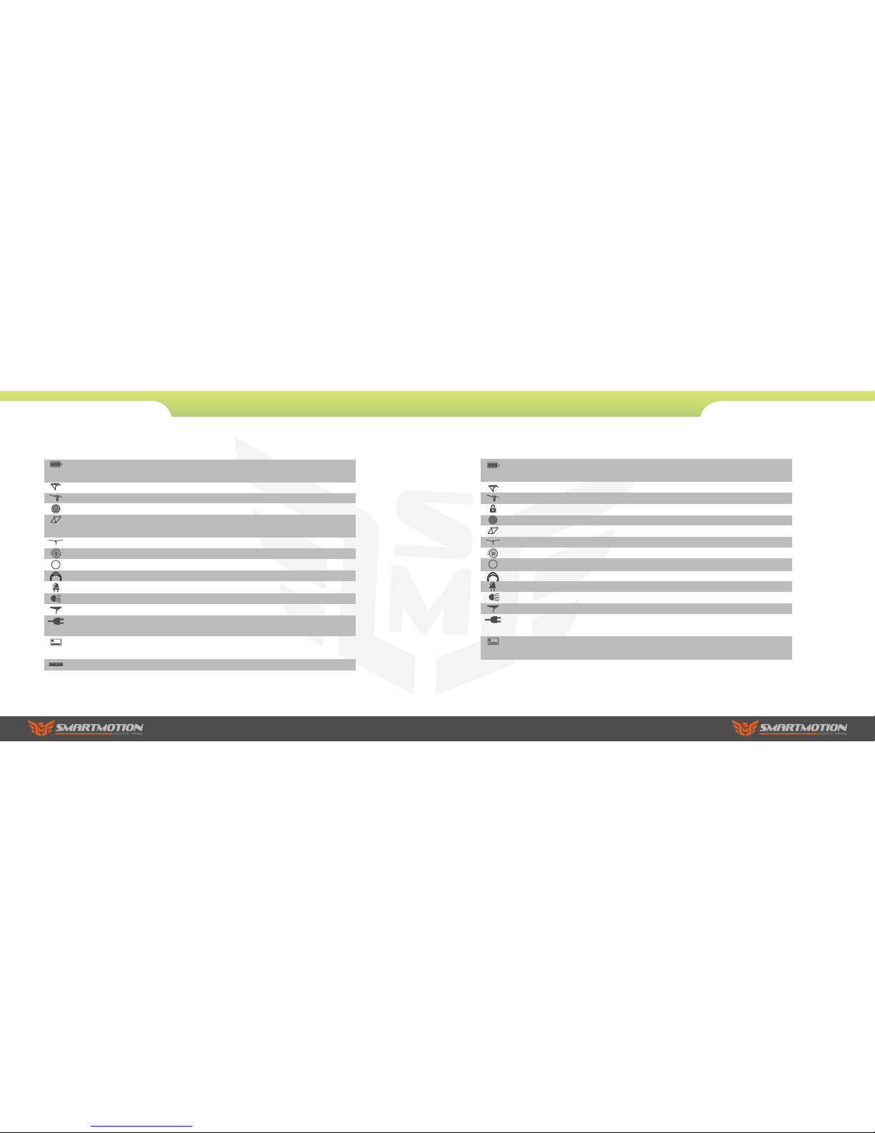
36v10.4ah lithium ion for NZ conditions - superior weatherproofing. USB
charge port.
Heavy duty rear battery rack, with elastic for luggage.
Tektro front rear brake.
Shimano Nexus 3 speed internal hub gears and Revo shifter.
Alloy folding frame and foldable pedals.
Centre-mounted adjustable kickstand.
Height adjustable folding handle bars for relaxed, upright ride posture.
Polypropylene guards with heavy duty stays.
Kenda, Kevlar guard, 20 X 1.95.
20” alloy rims.
LED console with 5 levels assist. Active throttle in all modes.
Integrated front and rear light powered from the main battery.
Velo plush comfort seat.
Marine- rated cable plugs on all components for simple and quick servicing/replacement.
2 year warranty on battery and motor, 6 years on frame, 12 months other
parts.
90cm L x 62cm H x 43cm W (folded).
6. Main Specifications
Vista Essence
6. Main Specifications
BATT ERY
RACK
BRAKE
SECURITY
GEARS
FRAME
HANDLE
MUDGUA RD
TYRE
RIM
DISPLAY PANEL
LIGHTS
SE AT
CABLES
WARRANTY
36v10.4ah lithium ion for NZ conditions - superior weatherproofing. USB
charge port.
Heavy duty rear battery rack, with elastic for luggage.
Tektro front rear brake.
Integrated frame C-lock for easy security (locks the rear wheel).
Shimano Nexus 3 speed internal hub gears and Revo shifter.
Alloy frame. Centre-mounted adjustable kickstand.
Adjustable headset. Comfort handgrips.
Polypropylene guards with heavy duty stays.
CST Commuter, Kevlar guard, 26 X 1.9.
Colour-matched Alex GX-2100 alloy.
LED console with 5 level assist. Active throttle in all modes.
Integrated front and rear light powered from the main battery.
Velo plush comfort seat.
Marine- rated cable plugs on all components for simple and quick
servicing/replacement.
2 year warranty on battery and motor, 6 years on frame, 12 months other
parts.

7. Do’s and Don’ts
Do treat your eBike like any bicycle you would want
to last well… keep it stored somewhere secure and
away from the elements.
Don’t treat your eBike as a dirt-bike! The motor and
battery are weather proof, but not water-tight. It is
ok in rain, but not to ford streams, etc!
Never take your eBike on the beach as salt water
and sand will drastically shorten the lifespan of
many of the ebike’s components (motor, gears,
wiring connections, etc).
Note: Your warranty is void if evidence of salt, sand,
or water damage are present within the components. Important: If you live very close to the sea
you must keep your bike indoors when not in use.
This will save you $$$ as your components will last
longer.
Don’t power up the throttle while the eBike is held
stationary. Motor operation for more than a few
seconds while the wheel is locked/stationary can
damage the motor and controller.
Note: It is okay to take off from stationary using the
throttle.
Important: Your bike will arrive with the battery
partially charged. You need to give it a full charge
before ANY use. Smartmotion batteries have been
precondition-cycled, so no need to do 3 full deep
discharges as for some other brands. Just charge
and go... then just top your battery up after each
use (lithium batteries prefer shallow discharge).
Then give your battery a complete discharge and
full charge every 3 months or so to keep the cells
well balanced.
Note: The LCD battery display bars will dip under full
load (on hills, etc). This is normal as running voltage
drops under high load. To get an accurate battery
reading, wait about 10 sec after the motor is not in
use. The 8 step capacity lights on the battery will
give you a more accurate idea (button on top rear of
battery – more info later in manual).
Do take extra care on the road as you will be travel-
ling faster than you normally do on a bike and your
bike is now power-assisted, so will behave differently.
7. Do’s and Don’ts
Don’t let others ride your eBike unless you have
properly explained safe and appropriate use to
them.
Don’t attempt to open the motor or battery should
your system malfunction. This will void the warranty. Return it to the store you purchased it from.
Do make sure your charger has free air movement
around it as it will get quite warm.
Don’t use your charger outdoors. It is for indoor use
only.
Do top up your battery whenever possible. Lithium
batteries actually prefer shallow discharge (the
exact opposite of older types of batteries that have
memory effects). Keeping your battery topped up
between rides will prolong the life of your battery
and give you more power too, as a full battery is
better on the hills.
Do disconnect your battery from the charger when it
is charged. Leaving it connected permanently when
not in use will shorten cell life.
Never leave a fully discharged battery uncharged
for more than a week… you will shorten the lifespan of your battery the longer you leave it in a fully
discharged state.
Don’t leave your battery for more than 3 months
without top-up charging it.
Note: A battery left for more than 3 months at a low
voltage may suffer cell damage. This will not be
covered under your warranty. It is to your advantage
to properly look after your battery as it is the most
expensive part of your ebike!
Important: Though the risk of battery fire with
charging Samsung or Panasonic 18650 cells is
considerably lower than cheaper, unbranded cells
(online data suggests about one in 40 million for
the cells we use - i.e., you are more likely to get
struck by lightening), it is still possible. Treat any
charging lithium battery (including SmartMotion) as
a potential fire risk (yes, this includes cellphones,
computers too). If charging your battery while it
is still docked into the bike simply make sure the
bike (includes charger) is not on or leaning against
a flammable surface. Same for charging battery
off the bike, make sure the battery and charger is
placed on a fire-rated surface (concrete floor, steel
bench or shelf, etc).

8. Display Panel Controls
On/Off
Press ON/OFF to start the display and power up
the bike.
To turn off, press the ON/OFF again.
Note: the display will power off after 5 minutes
without use.
Lights
Press to turn lights on and off.
Walk-along Feature
Hold 6kph for 2 seconds to enter into the mode
of power assist walk. The e-bicycle will go on
at a uniform speed of 6km/h until you let go of
pushing the button
Your display is easily controlled with 3 buttons located
on your handlebars.
MODE
6km/h
Pedal Assist
Press mode button, it shifts between 20%, 40%,
60%, 80%, 100%, 20% meaning low assistance from
motor, 100% meaning full assistance from motor.
The higher %, the more assistance. The default
mode is 20%.
You will notice that after one turn of the pedals the
motor will start working, assisting you to ride the
bike by adding power to the front wheel. This is the
standard or pedelec mode. To continue using the
pedelec mode you must keep turning the pedals; if
you stop the motor will stop and the bike will slow to
a halt. If you start pedaling again after one turn the
motor will start again.
Depending what country you are in, your throttle will
have different functionalities. In EU and Australasia,
It will work to 6kph unassisted, then only function
above that if you are pedaling. In other countries
it will be fully active whether you are pedaling or
not. If the bike is turned on, always be careful when
mounting the bike that you do not twist the throttle,
as the bike can accelerate away from you and cause
injury. Note: your brake levers have sensors that
will automatically cut motor power when you use
the brakes and restore it when you release the brake
levers.
8. Display Panel Controls

Battery Removal
To remove the battery, insert the key into the lock
on the front left side of battery rack and turn the
key, then pull the battery (using the underside
finger groove) to slide it out the back of the rack.
Note: the lock is not automatic, so key is required to
reload the battery… simply slide it back in until it
locks, making sure you are correctly on the slide rail
first.
9. Battery Instructions
Charging your Battery
You can charge the battery on or off the bike. The
charge terminal is on the front of the battery. Plug
the charger into the wall and switch on. Turn on
the battery then lift the rubber cap and plug in
your charger. The charge light on the charger will
show red, and turn green when the battery is fully
charged.
Plugging a live charger into the battery while it is
turned off can create a spark.
Note: be careful to properly reinstall the rubber cap
before re-using your bike.
Power On/Off
On the centre rear of the battery is the power on/off
button. When pushed in, the led inside the button
will light, indicating the battery output power is
live. It is good practice to turn the battery off when
leaving your bike (press the button so it clicks out,
and the red led fades). This also makes your bike
safer as cannot be turned on from the handlebar
console.
Note: if you leave the battery on, but do not use the
bike, it will enter sleep mode after several hours and
power down (red light will go out). To reactivate the
battery, push the button to ‘click it out’, then push
again to click it back in again, and the led will light
up, indicating the battery is live again. Note: when
charging the battery off the bike, always turn the
power off before redocking to the bike (if battery
power is on there will be a spark as the terminal
reconnects to the bike, which causes damage to the
battery socket and reduces conductivity).
Connections
All ebike components (throttle, brake sensors,
controller, etc) on the SmartMotion bikes have
isolating marine-rated plugs, so, should you
damage a component, replacement is easy. Take
the bike to your local dealer and they will order a
replacement pair
9. Battery Instructions

USB Charging Port
The SmartMotion battery has been updated with
a USB 2.0 charging port. Use this to charge your
phones and other USB devices. It has a 1.0 amp
max output. Important: the rubber cap for the USB
2.0 terminal MUST be properly reinstalled after
USB charging, otherwise moisture can get inside
the battery and damage the inner components.
Warranty is void if evidence of water ingress via
USB port is present.
Capacity
You can check the capacity of your battery by
pushing the capacity button on the top rear of the
battery.
Precondition: The power button was already turned
on ( Red LED was lit as the picture shows ).
9. Battery Instructions 10. Warranty
Warranty
Your SmartMotion bike is covered by the following
extensive Warranty
Battery
2 years (warranted to still supply at least 60% of rated
capacity after 2 years)
Motor
2 years
Frame
6 years (frame structural integrity – not including general wear and tear)
Other Components
1 year (not including consumables; cables, tyres, handgrips)
Only use genuine replacement parts available through
your local dealer.
Exceptions to Warranty
1. Damage resulting from misuse, not maintaining the
bicycle, or not following the guidelines within this user
guide. Accidental or deliberate damage.
2. Failure to meet the six-monthly service schedule.
3. Damage due to private repair or alteration by user or
unauthorized service centre.
4. Failure to produce invoice or proof of purchase.
5. Failure to meet the six-monthly/1000km service
schedule.
Important: Though the risk of battery fire with
charging Samsung or Panasonic 18650 cells is
considerably lower than cheaper, unbranded cells
(online data suggests about one in 40 million for
the cells we use - i.e., you are more likely to get
struck by lightening), it is still possible. Treat any
charging lithium battery (including SmartMotion) as
a potential fire risk (yes, this includes cellphones,
computers too). If charging your battery while it
is still docked into the bike simply make sure the
bike (includes charger) is not on or leaning against
a flammable surface. Same for charging battery
off the bike, make sure the battery and charger is
placed on a fire-rated surface (concrete floor, steel
bench or shelf, etc).

11. Service Checklist
Check for damage Adjust and Tension
Lubricate
Frame & Fork
Rims
Cables & connections
Spokes*
Gears
Seat
Reflectors & Lights
Handlebars, Stem, Grips
Brakes
Cranks & Bottom Bracket
Wheel Axles
All Fasteners
Chain
Derailleur
Seatpost
*Spokes to be tensioned to 130Nm
Model:
Serial Numbers:
Dealer:
Purchase Date:
6 Weeks/200km
Date:
Shop:
Mechanic:
6 Months
Date:
Shop:
Mechanic:
24 Months
Date:
Shop:
Mechanic:
12 Months
Date:
Shop:
Mechanic:
12. Service Record


www.smartmotionbikes.com
 Loading...