


User Manual
Sports user manual.indd 1 7/15/2016 4:57:03 PM
Contents
1. Contents of shipping carton
2. Assembly instructions
3. Safe Riding Recommendations
4. Maintenance & Adjustment
5. Main Specications
6. Do’s and Don’ts
7. Display Panel
8. Display Panel Controls
9. Battery instructions
10. Warranty
11. Service Checklist
12. Service Record
User Manual 1. Assembly Instructions
Congratulations for purchasing a SmartMotion electric bicycle!
Please read this guide fully BEFORE using your electric bike.
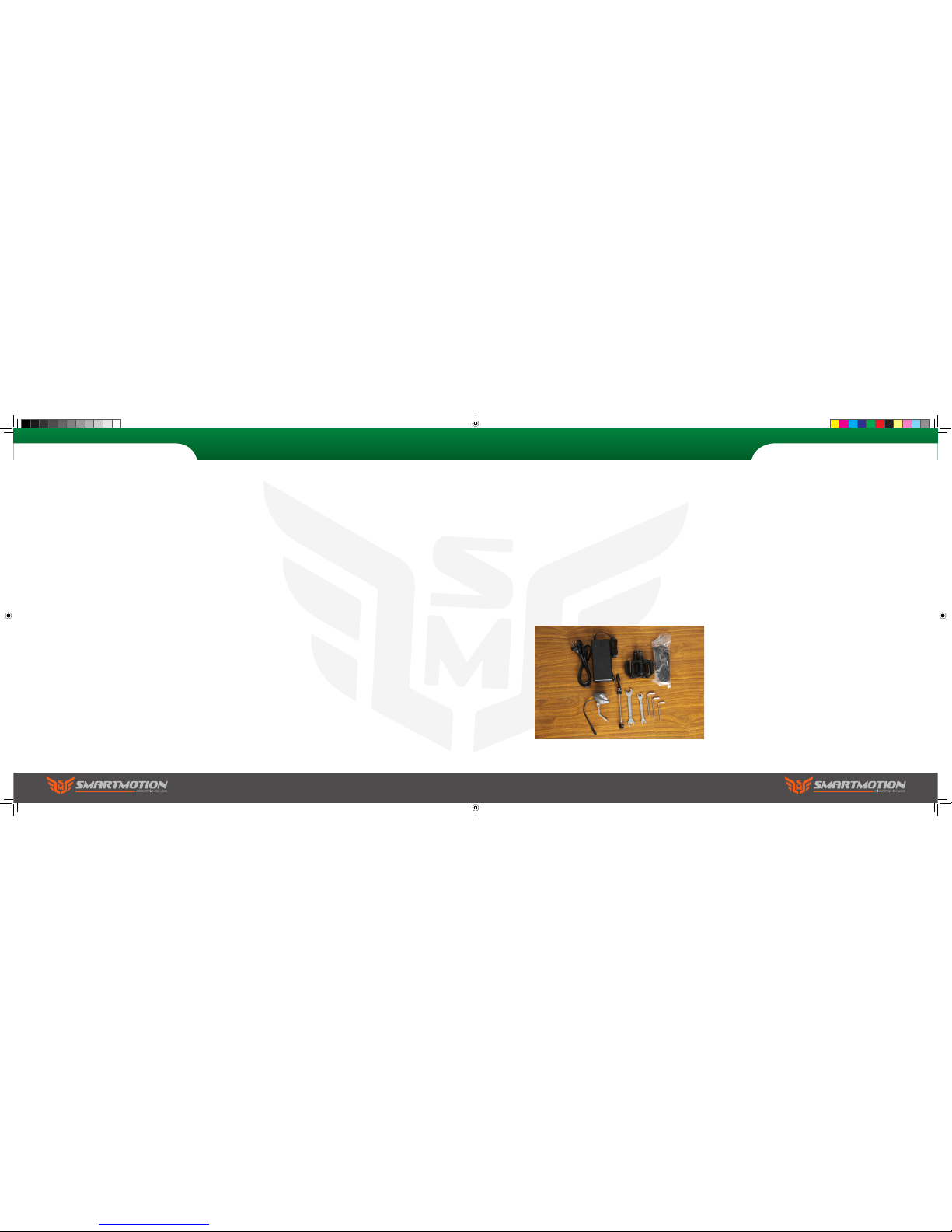
In the Pacer box you will nd the following items:
1. SmartMotion electric bicycle
2. Battery charger
3. 2X Pedals
4. Tool kit (4mm, 5mm & 6mm allen key,
8mm/10mm spanner, 15mm spanner)
5.
2X keys for battery lock
6. Front wheel quick release axle
7. Front light
8. Elastic strap
Pacer
Sports user manual.indd 2-3 7/15/2016 4:57:09 PM
To Prepare
We recommend that you familiarise yourself
with the bike parts before assembling. Gather all
required tools. Be sure to work in a clean, dry space
with plenty of room. You might wish to lay down a
tarpaulin or old blanket to protect the bike during
assembly. You may nd it helpful to stand the bike
frame on a block or sturdy box under the battery
housing to work with it in an upright position.
Please watch the balance when installing wheels.
1. Unpack
a. Carefully lift the electric bike out from the carton
(two people recommended for this task). Cut the
nylon zip ties with suitable scissors and remove the
foam protection from the bike.
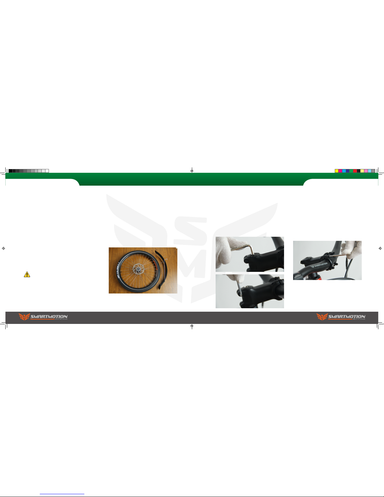
b. Remove the front wheel and mudguard from the
bike and put them aside. Carefully stand the bike
upright, resting on its forks when installing wheels.
Your electric bike is shipped 85% assembled. Follow
these steps to get it ready and safe for you to ride.
Do not activate the brakes until the bike is
fully assembled. Squeezing brake levers
while calipers have no disc rotor between
them can damage the brakes.
2. Fork
a. Slide the handle bar stem into the steering tube,
then fasten the centre screw using the 6mm allen
key to 6-8N.M. Turn the stem it to align it with the
forks correctly, then tighten the side pinch bolts to
6-8N.M. with a 5mm allen key to hold the stem in
the correct position.
b. Loosen the handle bar angle the four handlebar
clamp bolts and rotate the handlebar to make sure
the brake lever, shift lever and switch positions
are at the correct angle. Finally fasten the angle
adjusting bolt to 6-8N.M
2. Assembly Instructions
2. Assembly Instructions
Pacer
Pacer
Sports user manual.indd 4-5 7/15/2016 4:57:30 PM

3. Mudguard
Install the front mudguard and front light on the
fork. Take off the bolt from the front fork, put the
front mudguard hanger mount on the inside or
outside of the fork then put the front light bracket
on. Put the bolt through the fork then fasten the
bolt with a 5mm allen key and 10mm spanner.
Then fasten the two mudguard stays to the forks.
Finally connect the light cable to the front light.
4. Light Connection
Finally connect the cable from the front light to the
cable connection coming out on the underside of
the down tube, making sure the arrows align before
pushing the connectors together.
2. Assembly Instructions
5. Seat
Release the seat post clamp lever and set the
seat post height to the position which is suitable
for you to comfortably reach the ground when you
are sitting on the bike, then refasten the seat post
clamp. The maximum height should be within the
max height markings on the seatpost.
6. Pedals
Attach the pedals to the cranks, paying attention
to the “L” or “R” marked on the pedal axles. Note:
the pedals have opposing threads – screw in the left
pedal counterclockwise and screw in the right pedal
clockwise. Install L pedal counterclockwise and the
right pedal clockwise.
2. Assembly Instructions
Pacer Pacer
Sports user manual.indd 6-7 7/15/2016 4:58:20 PM
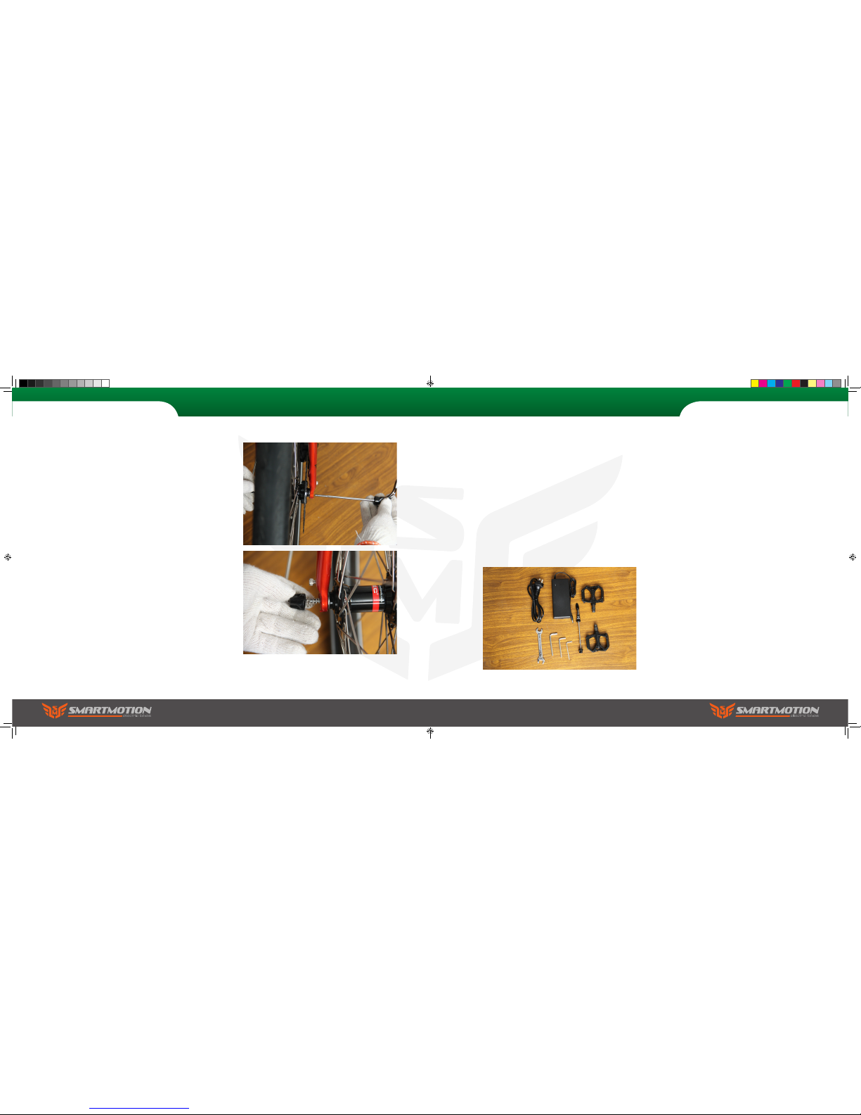
7. Front wheel
Assemble the front wheel quick release axle by
pushing it through the hollow hub, making sure
that one spring is on each side of the hub. Then
screw on the end nut several turns. Next, carefully
lift the bike front forks off the ground and lower the
forks onto the wheel axle, being careful the disc
rotor ts correctly into the disc calipers (this job is
best with 2 people). Tighten the non-rotor side nut
nger tight and try to close the quick release lever.
Loosen or tighten the nut until it takes the correct
amount of force to close the lever. It should be hard
to close, but not so hard you cannot fully close it. It
must fully close (as in picture) otherwise the wheel
may come loose, causing serious injury. Note: if
you are not well trained in cycle assembly, this
procedure must be checked by a cycle technician.
2. Assembly Instructions
Pacer
2. Assembly Instructions
Catalyst
In the Catalyst box you will nd the following items:
1. SmartMotion electric bicycle
2. Battery charger
3. 2X Pedals
4. Tool kit (4mm, 5mm & 6mm allen key,
8mm/10mm spanner, 15mm spanner)
5.
2X keys for battery lock
6. Front wheel quick release axle
Sports user manual.indd 8-9 7/15/2016 4:58:46 PM

2. Fork
a. Slide the handle bar stem into the steering tube,
then fasten the centre screw using the 6mm allen
key to 6-8N.M. Turn the stem it to align it with the
forks correctly, then tighten the side pinch bolts to
6-8N.M. with a 5mm allen key to hold the stem in
the correct position.
b. Loosen the handle bar angle the four handlebar
clamp bolts and rotate the handlebar to make sure
the brake lever, shift lever and switch positions
are at the correct angle. Finally fasten the angle
adjusting bolt to 5-8N.M.
2. Assembly Instructions
Catalyst
To Prepare
We recommend that you familiarise yourself
with the bike parts before assembling. Gather all
required tools. Be sure to work in a clean, dry space
with plenty of room. You might wish to lay down a
tarpaulin or old blanket to protect the bike during
assembly. You may nd it helpful to stand the bike
frame on a block or sturdy box under the battery
housing to work with it in an upright position.
Please watch the balance when installing wheels.
1. Unpack
a. Carefully lift the electric bike out from the carton
(two people recommended for this task). Cut the
nylon zip ties with suitable scissors and remove the
foam protection from the bike.
b. Remove the front wheel and from the bike and
put them aside. Carefully stand the bike upright,
resting on its forks when installing wheels.
Your electric bike is shipped 85% assembled. Follow
these steps to get it ready and safe for you to ride.
Do not activate the brakes until the bike is
fully assembled. Squeezing brake levers
while calipers have no disc rotor between
them can damage the brakes.
2. Assembly Instructions
Catalyst
Sports user manual.indd 10-11 7/15/2016 4:59:29 PM

5. Front wheel
Assemble the front wheel quick release axle by
pushing it through the hollow hub, making sure
that one spring is on each side of the hub. Then
screw on the end nut several turns. Next, carefully
lift the bike front forks off the ground and lower the
forks onto the wheel axle, being careful the disc
rotor ts correctly into the disc calipers (this job is
best with 2 people). Tighten the non-rotor side nut
nger tight and try to close the quick release lever.
Loosen or tighten the nut until it takes the correct
amount of force to close the lever. It should be hard
to close, but not so hard you cannot fully close it. It
must fully close (as in picture) otherwise the wheel
may come loose, causing serious injury. Note: if
you are not well trained in cycle assembly, this
procedure must be checked by a cycle technician.
3. Seat
Release the seat post clamp lever and set the
seat post height to the position which is suitable
for you to comfortably reach the ground when
you are sitting on the bike, then refasten the
seat post clamp. The maximum height should be
within the max height markings on the seatpost.
4. Pedals
Attach the pedals to the cranks, paying attention
to the “L” or “R” marked on the pedal axles. Note:
the pedals have opposing threads – screw in the left
pedal counterclockwise and screw in the right pedal
clockwise. Install L pedal counterclockwise and the
right pedal clockwise.
2. Assembly Instructions 2. Assembly Instructions
Catalyst Catalyst
Sports user manual.indd 12-13 7/15/2016 5:00:08 PM

3. Safe Riding Recommendations
1. Please observe trafc regulations, and don’t lend your
bicycle to anyone who is unfamiliar with it. The bicycle can
legally only be used on the road by a person aged 14 years or
over.
2. If you are in a country where wearing a cycle helmet is not
compulsory, we still strongly advise you to always wear one.
If you are unfamiliar with cycling, we also advise you to attend
a cycle prociency course prior to using it, or gain advice from
your local SmartMotion dealer. Your eUrban is not a toy and
should be considered a serious mode of transport.
3. As with all bicycles it is important that you stay within safe
limits. If you feel you are traveling too quickly for the road
conditions you probably are, so slow down! High speed will
increase forces in the case of an accident and increase the
possibility of injury.
4. Test your brakes prior to using the bike every time you use
it and remember the bike will not stop as quickly in wet or icy
conditions as it would on a dry road.
5. Check the tyres, rims, pedals, stem, cables, chain, etc for
general condition regularly.
6. A rider is very difcult for motorists and pedestrians to see
at dusk, at night, or at other times of poor visibility. If you must
ride under these conditions, check and be sure you comply
with all local laws about night riding; follow the rules of the
road. Take the following additional precautions: make sure that
your bicycle is equipped with correctly positioned and securely
mounted reectors, wear light-colored, reective clothing
and or accessories (any reective device or light source that
moves will help you get the attention of approaching motorists,
pedestrians and other trafc). Make sure your clothing or
anything else you are carrying on your bicycle doesn’t obstruct
a reector or light. Ride slowly when conditions demand you to
do so.
7. Check the front and rear rim’s safety line. Replace wheel
when any part of the Rim Wear Groove is not visible. It is
dangerous not to do so.
8. If a rear child seat is tted, before putting your child in, read
the full safety instructions of the seat manual to check seat is
installed correctly and child is fastened properly.
9. You must not leave the bike unattended or use the kickstand
to stand the bike without your support when a child is in the
rear seat as the bike could tip over and cause serious injury.
10. Make sure the rear suspension underside of your seat is out
of reach of your child to avoid nger injury.
11. Your bicycle must be returned to your servicing dealer
or bicycle/motorcycle mechanic after one month or 200km
of riding (which ever comes rst) to re-tension the spokes.
Then every six months or 1000km (which ever comes rst)
for a general service and thorough inspection. Failure to do
this can void your warranty due to unnecessary wear.
3. Safe Riding Recommendations
Pre-ride Checklist
Please make sure the brake lever sequence is
correct for your country before riding. In UK, NZ
and Australia the left brake lever is for rear brake
and the right brake is for the front brake. In all
other countries it is the other way: left for front,
right for rear.
Check the tyres for any visible damage.
Check tyre pressures are 40-60psi, and adjust if
necessary.
Check for any loose nuts, bolts, or xings.
Check brake functions, cable tension, pad
clearance, etc.
Check all electronic functions are ok (functions
detailed later in this manual).
Check the reectors are in place and the lights are
working (detailed later in manual).
Torque Settings
Check bolts are tightened according to the following
recommendations before you set off for the rst time.
a. Seat pillar clamp nut/bolt 5N.M-8N.M
b. Brake cable anchor bolt 5N.M
c. Brake centre bolt 11N.M
d. Seat angle clamp bolt 24N.M
e. Crank axle nuts R:42N.M
L: 46N.M
f. Gear shifter nuts 4N.M
g. Rear carrier nuts 8N.M
h. Mudguard bracket nuts 8N.M
i. Handle bar clamp nut 17-20N.M
j. Quill stem bolt 19N.M
k. Seat tube clamp nut 4-7N.M
l. Rear wheel axle nuts 40-45N.M
m. Quick release front axle. Measured torque
not typically used. Common industry practice is
resistance at lever half way through swing from
open to fully closed.
For all other nuts, the torque depends on the nut
diameter: M4 2.5-4.0N.M
M5 4.0-6.0N.M
M6 6.0-7.5N.M
Note: make sure axle nuts are always done up tight
on both wheels as connections to the motor and the
dropouts can be damaged due to the axle spinning.
Sports user manual.indd 14-15 7/15/2016 5:00:08 PM

3. Cleaning your electric bike
Warm soapy water and a cloth can be used to clean
the frame of your bike, but care must be taken not
to immerse any of the electrical components; they
are rainproof but cannot be immersed in water. The
motor can be cleaned with a soapy cloth, but also
must not be immersed in water. The battery can be
cleaned with a damp cloth, then dried afterwards.
Note: in salty conditions it is essential to clean and
lube your bike regularly.
4. Other Maintenance
Your bicycle must be returned to your servicing
dealer or bicycle/motorcycle mechanic after one
month or 200km of riding (which ever comes rst)
to re-tension the spokes. Then every six months
or 1000km (which ever comes rst) for a general
service and thorough inspection. Failure to do this
can void your warranty due to unnecessary wear
and tear.
Excluding the electric drive side of things, your
SmartMotion bicycle is a normal bicycle, with
normal components. Your dealer will be able to
explain to you the general care and maintenance of
the normal bicycle components. You should pop
your bike in for a check-up after about a month’s
use as new gear and brake cables will stretch, then
every 6 months after that.
The electric drive system is maintenance free and
has self-diagnostic codes that will be displayed on
the LCD console (detailed later in this user guide)
should anything go wrong. Again, speak to your
dealer should any issues arise.
4. Maintenance & Adjustment
1. Gear Adjustment
Adjust the rear derailleur cable tension to align
guide pulley with the centre of the cogs (setting this
in gear 3 or 4 is easiest). Low adjustment: In 1st
gear check and if necessary, turn the L adjustment
screw so that the guide pulley moves to a position
directly in line with the largest (1st gear) sprocket.
High adjustment: turn the crank arm while gear
shifting the derailleur to move the derailleur to the
top gear position, and then check and if necessary,
turn the H adjustment screw to adjust so that the
guide pulley is in line with the outer line of the
smallest sprocket when looking from the rear.
Turn the crank arm to set the derailleur to the low
position.
b. Adjust the front derailleur so that there is a
clearance of 1-3mm between the chain guide and
the largest chainring. After tentatively tightening
the clamp bolt, align the at prtion of the chain
guide in parallel with the at surface of the largest
chainring. When the adjustment is complete,
tighten the clamp bolt.
In 1st gear on front and rear, check and if
necessary, turn the L adjustment screw so that the
clearance between the chain guide inner plate and
the chain is 0 – 0.5mm.
In 2nd gear on front and rear, check and if
necessary, turn the H adjustment screw so that the
clearance between the chain guide outer plate and
the chain is 0 – 0.5mm.
4. Maintenance & Adjustment
2. Lubrication
1.1 Once a month lubricate all pivot points
on your derailleur and the derailleur pulleys with
suitable chain lube.
1.2 Every three months lubricate the brake
lever pivots, gears and chain with suitable oil.
H adjustment screw
L adjustment screw
H adjustment screw
L adjustment screw
Sports user manual.indd 16-17 7/15/2016 5:00:12 PM

5. Main Specications
Pacer
5. Main Specications
FRAME
FORK
HEAD SET
HANDLE BAR
SEAT
SEAT POST
BRAKE
CHAINWHEEL
CHAIN
CASSETTE
FRONT HUB
SPOKES
RIM
TYRE
DEREAILLUER
MOTOR
SENSOR
DISPLAY
BATTERY
CONTROLLER
FRAME
FORK
HEAD SET
HANDLE BAR
SEAT
SEAT POST
BRAKE
CHAINWHEEL
CHAIN
CASSETTE
FRONT HUB
SPOKES
RIM
TYRE
MUDGUARD
DERAILLUER
MOTOR
SENSOR
DISPLAY
BATTERY
CONTROLLER LIGHT SYSTEM
27.5 Low step hydro formed top tube with integrated
controller and LCD. Small or Large size.
SR Suntour XCR32 Coil with 120mm travel, rebound
and lockout adjustment.
Neco integrated tapered.
31.8x720mm 30 rise.
Smartmotion Enduro.
30.4x400mm Alloy.
Tektro hydraulic with Tektro 180mm rotors.
32/42 170mm crank.
KMC X10e.
Shimano 11-36T.
Novatec.
Black Stainless.
27.5 Alex DP23 with eyelets.
Kenda 27.5x2.2 puncture resistant
Deore 10 speeds.
High torque brushless with freewheel.
Torque sensor including cadence sensor.
Full colour LCD in top tube. 5 Levels assist.
Samsung 36V 14.5ah.
Intelligent sine wave.
27.5 Low step hydro formed top tube with integrated
controller and LCD. Small or Large size.
Rigid alloy.
Neco integrated tapered.
31.8x720mm 15 rise.
Smartmotion Enduro.
30.4x400mm Alloy.
Tektro hydraulic with Tektro 180mm rotors.
48T 170mm crank.
KMC X10e.
Shimano 11-36T.
Novatec.
Black Stainless.
27.5 Alex DP23 with eyelets.
CST 27.5x2.0” C-1719
Polypropylene guards with heavy duty stays.
Deore 10 speeds.
High torque brushless with freewheel.
Torque sensor including cadence sensor.
Full colour LCD in top tube. 5 Levels assist.
Samsung 36V 14.5ah.
Intelligent sine wave.
Front integrated ood strip.
Rear integrated LED strips.
Front ROXIM LED.
Catalyst
Sports user manual.indd 18-19 7/15/2016 5:00:13 PM

6. Do’s and Don’ts 6. Do’s and Don’ts
Do treat your eBike like any bicycle you would want
to last well… keep it stored somewhere secure and
away from the elements.
Don’t treat your eBike as a dirt-bike! The motor and
battery are weather proof, but not water-tight. It is
ok in rain, but not to ford streams, etc!
Never take your eBike on the beach as salt water
and sand will drastically shorten the lifespan of
many of the ebike’s components (motor, gears,
wiring connections, etc).
Note: Your warranty is void if evidence of salt, sand,
or water damage are present within the components. Important: If you live very close to the sea
you must keep your bike indoors when not in use.
This will save you $$$ as your components will last
longer.
Don’t power up the throttle while the eBike is held
stationary. Motor operation for more than a few
seconds while the wheel is locked/stationary can
damage the motor and controller.
Important: Your bike will arrive with the battery
partially charged. You need to give it a full charge
before ANY use. Smartmotion batteries have been
precondition-cycled, so no need to do 3 full deep
discharges as for some other brands. Just charge
and go... then just top your battery up after each
use (lithium batteries prefer shallow discharge).
Then give your battery a complete discharge and
full charge every 3 months or so to keep the cells
well balanced.
Note: The LCD battery display bars will dip under full
load (on hills, etc). This is normal as running voltage
drops under high load. To get an accurate battery
reading, wait about 10 sec after the motor is not in
use. The 8 step capacity lights on the battery will
give you a more accurate idea (button on top rear of
battery – more info later in manual).
Do take extra care on the road as you will be
travelling faster than you normally do on a bike and
your bike is now power-assisted, so will behave
differently.
Don’t let others ride your eBike unless you have
properly explained safe and appropriate use to
them.
Don’t attempt to open the motor or battery should
your system malfunction. This will void the warranty. Return it to the store you purchased it from.
Do make sure your charger has free air movement
around it as it will get quite warm.
Don’t use your charger outdoors. It is for indoor use
only.
Do top up your battery whenever possible. Lithium
batteries actually prefer shallow discharge (the
exact opposite of older types of batteries that have
memory effects). Keeping your battery topped up
between rides will prolong the life of your battery
and give you more power too, as a full battery is
better on the hills.
Do disconnect your battery from the charger when it
is charged. Leaving it connected permanently when
not in use will shorten cell life.
Never leave a fully discharged battery uncharged
for more than a week… you will shorten the lifespan of your battery the longer you leave it in a fully
discharged state.
Don’t leave your battery for more than 3 months
without top-up charging it.
Note: A battery left for more than 3 months at a low
voltage may suffer cell damage. This will not be
covered under your warranty. It is to your advantage
to properly look after your battery as it is the most
expensive part of your ebike!
Important: Though the risk of battery re with
charging Samsung or Panasonic 18650 cells is
considerably lower than cheaper, unbranded cells
(online data suggests about one in 40 million for
the cells we use - i.e., you are more likely to get
struck by lightening), it is still possible. Treat any
charging lithium battery (including SmartMotion) as
a potential re risk (yes, this includes cellphones,
computers too). If charging your battery while it
is still docked into the bike simply make sure the
bike (includes charger) is not on or leaning against
a ammable surface. Same for charging battery
off the bike, make sure the battery and charger is
placed on a re-rated surface (concrete oor, steel
bench or shelf, etc).
Sports user manual.indd 20-21 7/15/2016 5:00:13 PM

Your display is easily controlled with 3 buttons located
on your handlebars
Walk Mode
Press and hold down for 2 seconds to enter into
the mode of power assist walk. The bike will go on
at a uniform speed of 6km/h and display 6km on
the screen.
Power On/Off
Press and hold for 3 seconds to start the
display and power up the bike. To turn off, press
and hold the button for 3 seconds.
Note: the display will power off after 5 minutes
without use.
Change mode
Touch to change modes.
Pedal Assist
Pedal Assist is controlled with the
buttons. Touch to turn the assist up, and
touch to turn it down.
Lights/Night Mode
With the display on, press and hold for 3
seconds to activate Night Mode. This will ip the
contrast colours of the LCD screen making it easier
to read in the dark. For the Pacer the lights will also
turn on. Press and hold again to turn off the
bicycle lights.
Setup
Press and hold together for 5 seconds to
enter the setup menu.
Touch to select the menu.
Use and to change the value.
Touch again to choose the “Save & Exit” option
to nish the setup.
7. LCD Display Panel Controls 7. LCD Display Panel Controls
Sleep Mode
If the bike remains stationary for 5 minutes, the LCD
automatically powers down.
USB Output Charging
User can charge phone, etc, via the USB output port
which is located above of the LCD, under a rubber
waterproof plug. As long as the battery is attached
the port is live. Make sure the plug is reinstalled
after charging.
Error Code Display
If there is something wrong with the electronic
control system, the display will show the error code
automatically. Should you receive an error code,
contact your local dealer for advice.
Before contacting service center check all plugs for
loose connections.
Sports user manual.indd 22-23 7/15/2016 5:00:13 PM

Battery Indicator
When the battery is full all ten battery segments
show. When the battery is low the bars will turn
red. The voltage will drop while the battery is
under load (motor running).
Lights
When the lights are off the bike icon remains
black. Once lights are turned on the icon turns
blue.
Speedometer
Large display of your current speed.
Trip Meter
Displays the distance you have travelled from
when you last tripped the meter.
Lights on
Lights off
Odometer
Displays the total distance the bike has
travelled.
Cadence/Torque/Walk-along
An icon will be displayed depending what mode
of assist.
Cadence measures your pedal rotation, but not
pressure. Use this mode for the easiest ride.
Torque mode measures your pedal pressure
and multiplies the output.
Walk-along will allow you to walk with the
bike with a small amount of assistance.
Power/Assist
The outer ring shows the level of assist
you have chosen.
The inner ring displays the real time
power usage.
8. LCD Display Panel 8. LCD Display Panel
Sports user manual.indd 24-25 7/15/2016 5:00:14 PM

9. Battery Instructions 9. Battery Instructions
Battery Removal
To remove the battery, insert the key into the lock
on the front left side of battery, turn and hold
the key, then pull the lever and slide the battery
sideways out of the down tube. To reload the
battery make sure the battery is correctly on the
slide rail then slide it back in until it locks.
Note: the lock is automatc, no key required to load
the battery.
Charging your Battery
You can charge the battery on or off the bike via one
of two ports. One is at the bottom of the battery,
the other is above the LCD screen. Lift the rubber
cap and plug in your charger. The charge light on
the charger will show red, and turn green when the
battery is fully charged. Note: be careful to properly
reinstall the rubber cap before re using your bike.
Power On/Off
On the top front of the battery is the power on/off
button. When pushed in, the LED lights below will
glow green, indicating the battery output power
is live. The number of LED glowing displays the
amount of battery capacitance.
Note: if you leave the battery on, but do not use
the bike, it will enter sleep mode after 4 hours and
power down (LED will go out). To reactivate the
battery just click the button and the led will light
up, indicating the battery is live again. Note: when
charging the battery off the bike, always turn the
power off before redocking to the bike (if battery
power is on there will be a spark as the terminal
reconnects to the bike, which causes damage to the
battery socket and reduces conductivity).
Sports user manual.indd 26-27 7/15/2016 5:01:05 PM

10. Warranty
Warranty
Your SmartMotion bike is covered by the following
extensive Warranty
Battery
2 years (warranted to still supply at least 60% of rated
capacity after 2 years)
Motor
2 years
Frame
6 years (frame structural integrity – not including general wear and tear)
Torque Sensor
1 year
Other Components
1 year (not including consumables; cables, tyres, handgrips)
Only use genuine replacement parts available through
your local dealer.
Exceptions to Warranty
1. Damage resulting from misuse, not maintaining the
bicycle, or not following the guidelines within this user
guide. Accidental or deliberate damage.
2. Failure to meet the six-monthly service schedule.
3. Damage due to private repair or alteration by user or
unauthorized service centre.
Important: Though the risk of battery re with
charging Samsung or Panasonic 18650 cells is
considerably lower than cheaper, unbranded cells
(online data suggests about one in 40 million for
the cells we use - i.e., you are more likely to get
struck by lightening), it is still possible. Treat any
charging lithium battery (including SmartMotion) as
a potential re risk (yes, this includes cellphones,
computers too). If charging your battery while it
is still docked into the bike simply make sure the
bike (includes charger) is not on or leaning against
a ammable surface. Same for charging battery
off the bike, make sure the battery and charger is
placed on a re-rated surface (concrete oor, steel
bench or shelf, etc).
USB Charging Port
The SmartMotion battery has been updated with
a USB 2.0 charging port. Use this to charge your
phones and other USB devices. It has a 1.0 amp
max output. Important: the rubber cap for the USB
2.0 terminal MUST be properly reinstalled after
USB charging, otherwise moisture can get inside
the battery and damage the inner components.
Warranty is void if evidence of water ingress via
USB port is present.
Connections
All ebike components (throttle, brake sensors,
controller, etc) on the SmartMotion bikes have
isolating marine-rated plugs, so, should you
damage a component, replacement is easy. Take
the bike to your local dealer and they will order a
replacement part.
9. Battery Instructions
4. Failure to produce invoice or proof of purchase.
5. Failure to meet the six-monthly/1000km service
schedule.
Sports user manual.indd 28-29 7/15/2016 5:01:09 PM

Model:
Serial Numbers:
Dealer:
Purchase Date:
6 Weeks/200km
Date:
Shop:
Mechanic:
6 Months
Date:
Shop:
Mechanic:
24 Months
Date:
Shop:
Mechanic:
12 Months
Date:
Shop:
Mechanic:
12. Service Record11. Service Checklist
Check for damage Adjust and Tension
Lubricate
Frame & Fork
Rims
Cables & connections
Spokes*
Gears
Seat
Reectors & Lights
Handlebars, Stem, Grips
Brakes
Cranks & Bottom Bracket
Wheel Axles
All Fasteners
Chain
Derailleur
Seatpost
*Spokes to be tensioned to 130Nm
Sports user manual.indd 30-31 7/15/2016 5:01:10 PM

www.smartmotionbikes.com
Sports user manual.indd 32 7/15/2016 5:01:10 PM
 Loading...