

SMART MAX GEOSYSTEMS MG970 User Manual
1 / 25
Smart Max Geosystems
MG970 GNSS RTK
User manual

2 / 25
Content
Ⅰ MG970 mainframe ................................................................................................. 4
1.1 Front side of the mainframe ........................................................................... 4
1.2 The bottom of receiver .................................................................................... 5
1.3 OLED display and Indicators ........................................................................ 6
1.3.1 The function of key ............................................................................... 6
1.3.2 The function og indicators .................................................................... 6
Ⅱ Basic operation of MG970 ..................................................................................... 7
2.1 Power on/off ..................................................................................................... 7
2.1.1 Power on ................................................................................................ 7
2.1.2 Power off ................................................................................................ 7
2.2 Instrument settings ......................................................................................... 8
2.2.1 Status icons ............................................................................................ 8
2.2.2Switch woke mode .................................................................................. 8
2.2.3Switch datelink and difference type ..................................................... 9
2.2.4 The rover mode ..................................................................................... 9
2.2.5 The base station work mode ............................................................... 10
2.2.6 Static record work mode .................................................................... 11
2.2.7 Check work station ............................................................................. 12
2.2.8 Self-checking ........................................................................................ 13
Ⅲ Connected to the PC ............................................................................................ 14
3.1 Connection Assistant software ..................................................................... 14
3.2 Settings ........................................................................................................... 16
3.3 Date download ............................................................................................... 21
3.4 Device register ............................................................................................... 22
3.5 Upgrade firmware ......................................................................................... 23
Appendix 1 Specification ............................................................................................. 24

3 / 25
Brief Introduction
MG970 is a multi-frequency and multi-satellite RTK survey system called the
pinnacle device of integrated RTK. It has higher integrated body, and makes a
breakthrough to solve the various problems in the RTK device design and
manufacture. MG970 also has stunning accuracy, stability resistance, strong
compatibility and environmental adaptability, the entire device is more portable,
user-friendly and reliable.
Each mainframe of MG970 built a four-feed GNSS antenna with zero phase center,
with P307 multi-frequency and multi-satellite board, full-band UHF radio transceiver,
GPRS \ CDMA network communication module, Bluetooth wireless transmission
module and Micro SD memory expansion module. Using industry-leading ARM
Cortex- M3 32-bit processor designed for the mainframe control system, and it
provides receiver outstanding computational performance and exceptional system
response to events.MG970 combined with multifunction buttons and a high-resolution
OLED screen, it can complete intelligent operation of the mainframe, can be viewed
the state of the receiver chain and data, can be set on the receiver, select receiver
mode, data link mode, the liberation of the hand book, and improve work efficiency
4 / 25
Ⅰ MG970 mainframe
In this chapter, it will show the detailed information of MG970, such as appearance,
interfaces and some basic operation.
The mainframe of MG970 is a flat cylindrical, 100mm in height, 191mm in diameter.
The front side is a LED screen, 2 functional buttons and 3 indicators. The back side is
a battery compartment.
The bottom of the receiver is some interfaces. They include a radio antenna interface,
a GPRS antenna interface, a 5 pin external power interface and a 7 pin RS232/USB
interface.
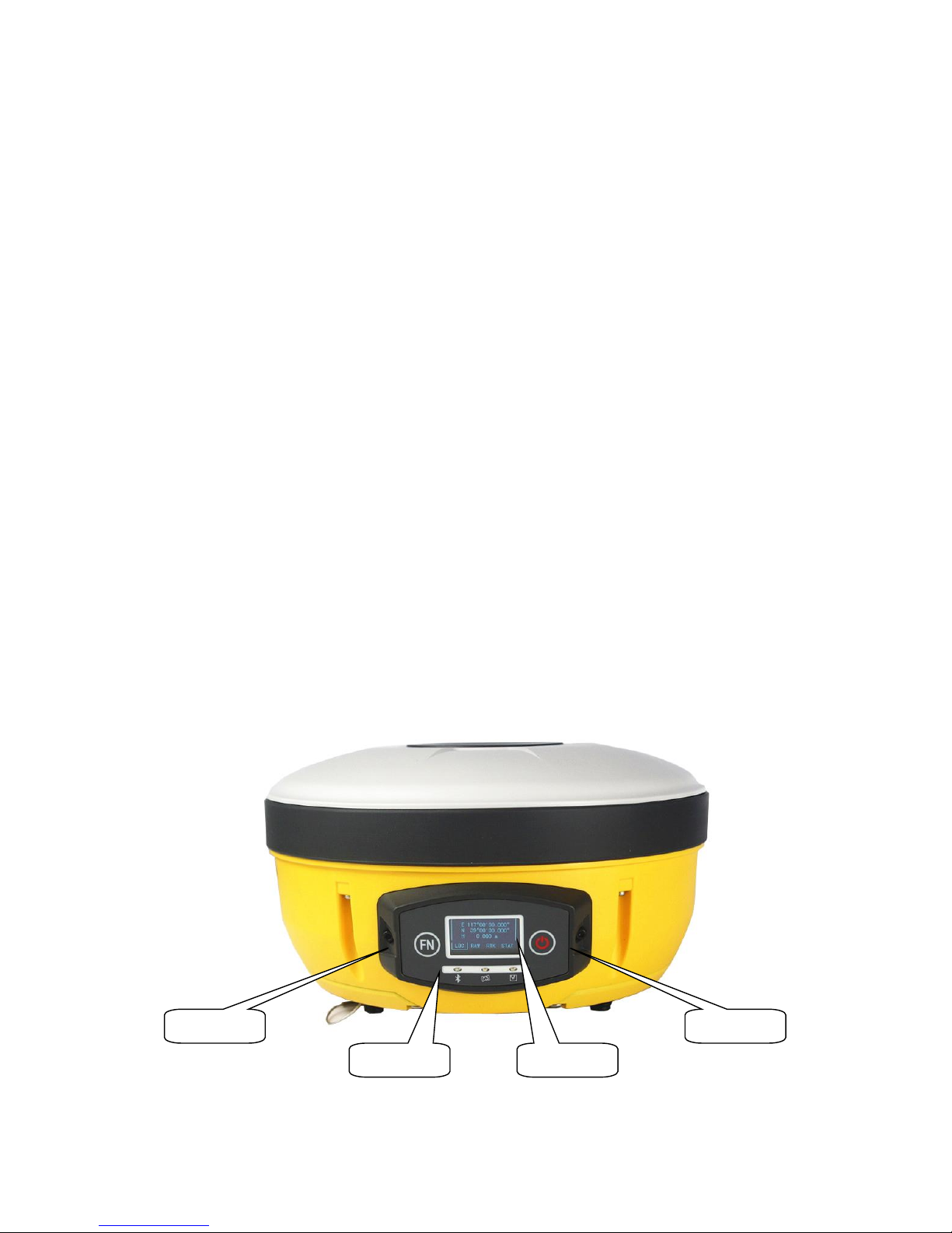
1.1 Front side of the mainframe
There are keys, OLED display and indicators in the front panel.
Power key
Function key
indicator
LED screen
5 / 25
Fig 1-1 Front panel
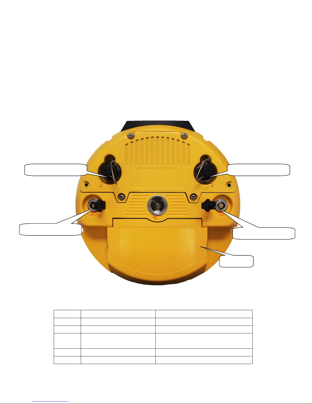
1.2 The bottom of receiver
There are some interfaces, battery compartment and a Screw hole in the bottom of
receiver.
Fig 1-2 Bottom
Number
Name
Function
1
Radio antenna interface
Connect to radio antenna
2
Network antenna interface
Connect to network antenna
3
7 pin interface
USB port, also can connect to
controller via the multi-function cable
4
Screw hole
Fix the receiver to tribrach or pole
5
5 pin interface
Connect to external radio and external
Battery
5 pin lemo interface
7 pin lemo interface
UHF antenna head
GPRS antenna head
6 / 25
battery
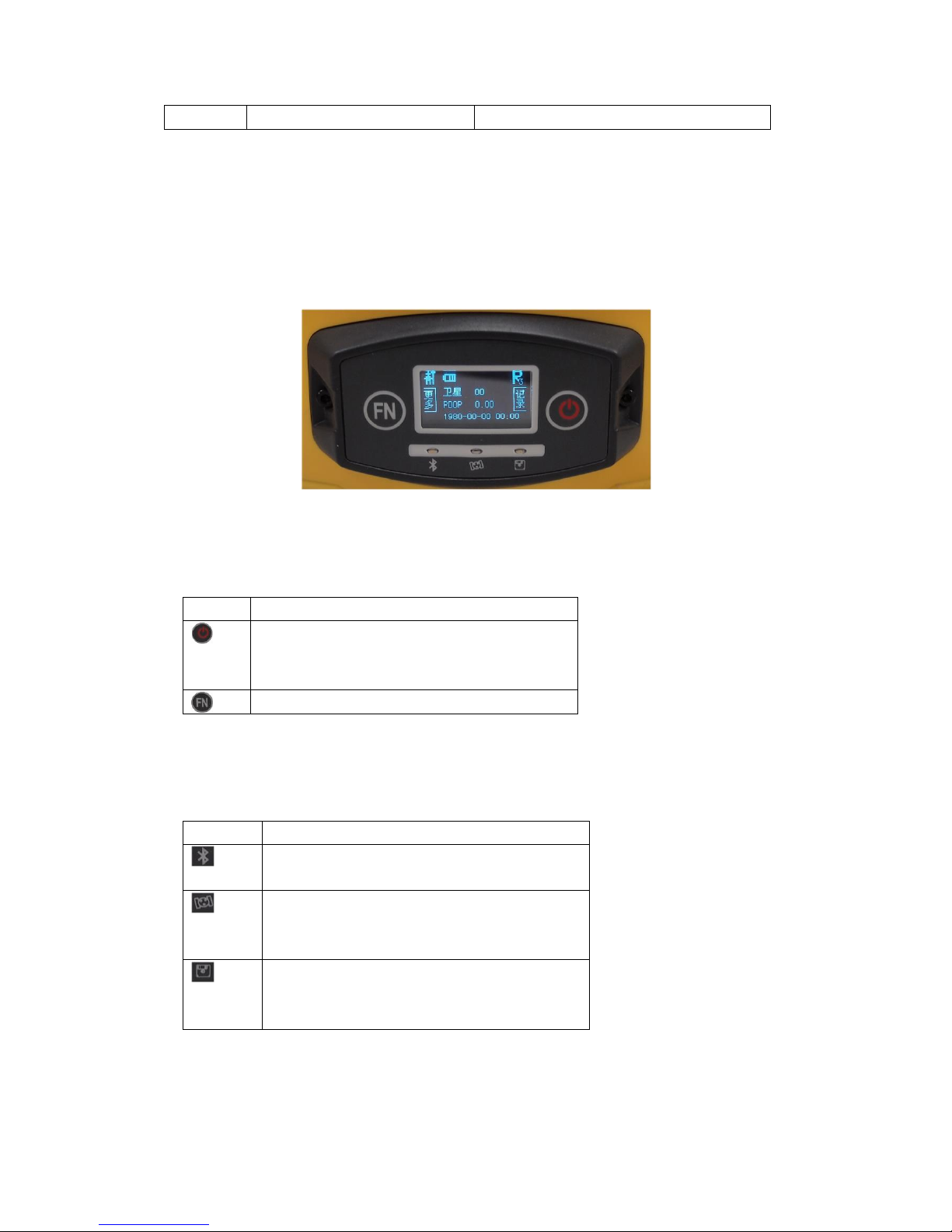
1.3 OLED display and Indicators
The panel includes two keys, three indicators and a OLED display. The function of
each component is described in detail below.
Fig 1-3 Panel
1.3.1 The function of key
Key
Function
Power key, Power on/off the receiver. Keep
press to enter main menu and as a confirm
key function key, make a selection
1.3.2 The function og indicators
Indicator
Function
Bluetooth indicator, It will be light when
MG970 connected via bluetooth
Satellite indicator, how many time it blink,
means how many satellites are locked,
cycle once every 5seconds
Static indicator, it will blink at sampling
interval when MG970 begin to record static
date

7 / 25
Ⅱ Basic operation of MG970
In this section, we highlight the basic operation of MG970. It includes powering
on/off, checking work station, changing work mode, self-checking. All of these
basic operations are simple and easy. But they are very important
2.1 Power on/off
This is the first step to use MG970, it’s very easy to operate. Below we will explain in
detail how to power on/off the mainframe.
2.1.1 Power on
When the receiver has battery, keep press power key for some seconds.
Fig 2-1 Power on page
About 5 seconds later, the buzzer will call three times, then the initialization is
completed and you will enter into the main page.
Fig 2-2 work mode: rover, base, static
2.1.2 Power off
Keep press power key in the state of powering on until enter into another menu. It
shows as follow:
Fig 2-3 setting menu
8 / 25
Then press function key to select. Switch to the “shut” icon, then press power key to
confirm. The mainframe will be powered off.
2.2 Instrument settings
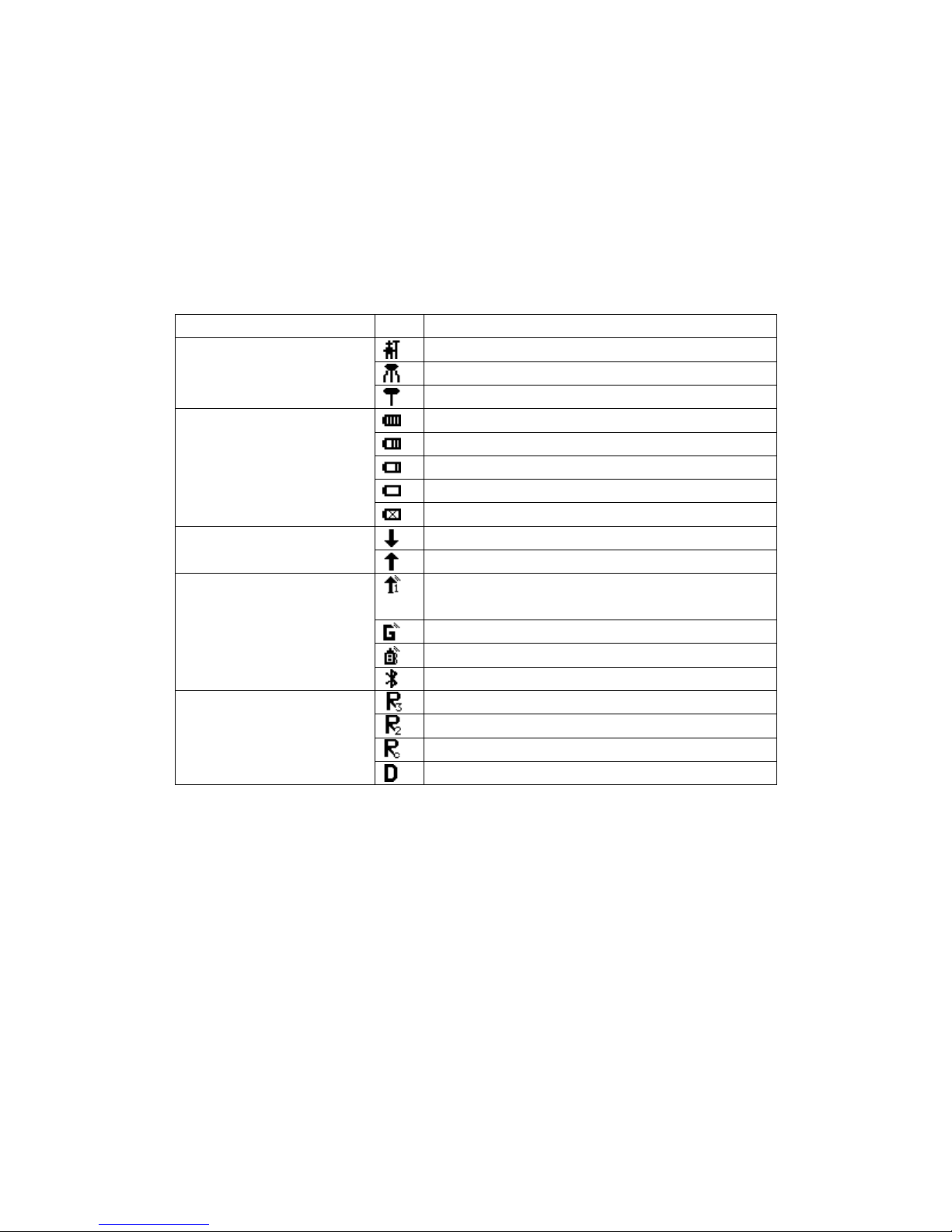
2.2.1 Status icons
Type
Icon
Description
Work mode
Rover mode
Base mode
Static mode
Power status
Full battery power or external power supply
Battery power remaining 3/4
Battery power remaining 2/4
Battery power remaining 1/4
The battery needs to be replaced
Date status
The Rover station is receiving difference
The base station is transmitting difference
Date link
UHF, number in right corner indicating the
channel
GPRS module
External Data Link
Bluetooth data link
Difference type
RTCM 3.0
RTCM 2.3
CMR
DGPS
2.2.2Switch woke mode
When we get a receiver, we should switch work mode first, it includes base, rover,
and static. Keep press power key in the state of powering on until enter into setting
menu. Then press the function key to switch to “mode”, and you can press the power
key to enter into the mode selection menu. Select the one you want to use, then press
power key to confirm.
 Loading...