

SMART MAX GEOSYSTEMS DE Series Repair Manual

0
Smart Max Geosystems CO.,Ltd
www.smartmaxgeosystems.com info@smartmaxgeosystems.com
Theodolite Repair Manual
INDEX
INDEX ........................................................................................................................... 0
1. Preface ....................................................................................................................... 1
2. Precautions ................................................................................................................. 2
3. Product Instruction ..................................................................................................... 3
3.1 External Components ........................................................................................ 3
3.2 Display And Keypad ......................................................................................... 4
4. Specifications Check And Adjustment ...................................................................... 5
4.1 Plat Vial ...................................................................................................................... 5
4.2 Circular Vial .............................................................................................................. 7
4.3 Laser Plummet .................................................................................................. 8
4.4 Inclination Of Telescope Reticle ..................................................................... 10
4.5 Laser Alignment Component .......................................................................... 11
4.6 Perpendicularity Between Line Of Sight And Horizontal Axis (C) ................ 13
4.7 Check of 2C .................................................................................................... 14
4.8 Vertical Index Difference (I) ........................................................................... 15
4.9 Vertical Index Difference Compensation ........................................................ 16
5. Disassemble the Inatrument ..................................................................................... 19
6. Circuit Section Check .............................................................................................. 25
6.1. Adjusting Tools ...................................................................................................... 25
6.2. Adjusting Method .......................................................................................... 25
6.2 Mainboard ....................................................................................................... 26
7. Failure Maintenance ................................................................................................ 27
7.1 Common Failure ............................................................................................. 27
7.2 Error Code And Failure Maintenance ............................................................. 29

1
Smart Max Geosystems CO.,Ltd
www.smartmaxgeosystems.com info@smartmaxgeosystems.com
1. Preface
The DE Series electronic theodolite uses the incremental grating and absolute
encoder system for angle measurement. Microcomputer technology is employed to
realize measurement, calculation, display, storage and other functions. Horizontal or
vertical angle and other measurement results can be displayed at the same time. There
is variety of modes to survey the angle, slope, etc.
The DE Series can be widely applied to the class 3/4 triangle survey. It can also be
used in various engineering surveys, such as railway, highway, bridge, water
conservancy, mine, etc. and the installation of buildings and large equipments, as well
as cadastral and topographic surveying.
This manual is applicable to DE2A, DE2A-L, DE2B, DE5A, DE5B, DE10A,
DE10B and other DE Series electronic theodolite. The numbers 2, 5, 10 means the
precision of angle measurement; A means with compensator; B means without
compensator.

2
Smart Max Geosystems CO.,Ltd
www.smartmaxgeosystems.com info@smartmaxgeosystems.com
2. Precautions
1. When failure occurs, please follow the instruction of this manual and debug as the
photos guidance. If the instrument damage is caused by personal behavior going against
service manual, the responsibility is definitely belongs to individual.
2. If the instrument failures involving some main components, such as mainboard,
grating disk, reading terminal, telescope LCD, etc., please replace the whole component.
Do not repair it.
3. When replacing components, please strictly according to the service manual. Do not
disassemble the instrument unauthorized if the repairing method is not involved in this
manual. In this case, please send it back to our company for repair.
4. After replacing components, you should calibrate the overall specifications. Before
using the instrument, please confirm all the specifications eligible.
5. Electronic theodolite is a precision instrument. If you don’t have professional
maintenance skills or equipment, do not repair the total station unauthorized to avoid
damaging it.
6. This service manual is only for the DE Series of Smart Max Geosystems CO.,Ltd.
Anything unclear during maintenance, please contact us.

3
Smart Max Geosystems CO.,Ltd
www.smartmaxgeosystems.com info@smartmaxgeosystems.com
3. Product Instruction
3.1 External Components
4
Smart Max Geosystems CO.,Ltd
www.smartmaxgeosystems.com info@smartmaxgeosystems.com
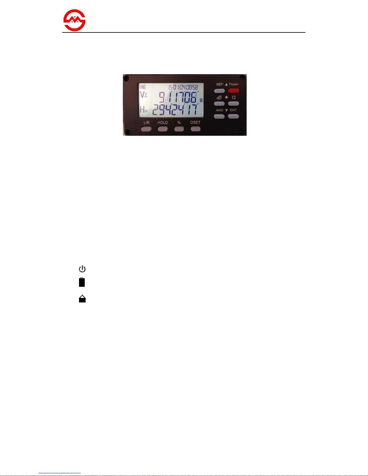
3.2 Display And Keypad
a. Display
The adopted LCD can display angle, words, date, time or other information. There
are ten buttons on display. The red button is a power switch button. Under angle
measurement mode, other functions are illustrated as follow:
L/R: switch left/ right of horizontal angle measuring direction
HOLD: lock horizontal angle measurement result
%: switch vertical angle/ slope percent
OSET: set horizontal angle as 0°00′00″
¤-▲: turn on/ off directing laser
¤-▼: turn on/ off laser plummet
¤-◆: turn on/ off background light of LCD
¤-ENT: enter main menu
¤-ENT-ENT: save and exit
b. Illustration Of Symbols On Screen
: automatic shutdown symbol
: battery power symbol
: special function symbol;
shows when press ¤ button and disappears after another press
%: slope percent
b-OUT: vertical angle over compensated
OUT: slope over ±100%
m: unit in meters
°, ′, ″: unit of angle
5
Smart Max Geosystems CO.,Ltd
www.smartmaxgeosystems.com info@smartmaxgeosystems.com
4. Specifications Check And Adjustment
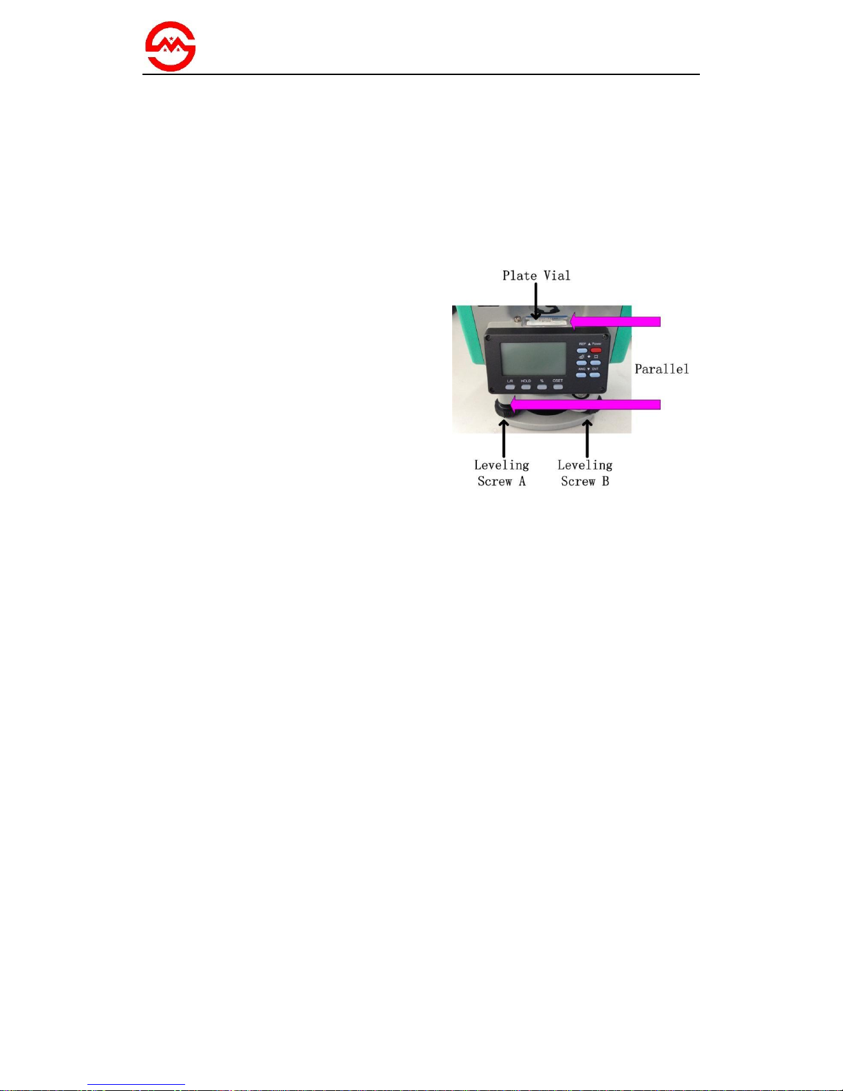
4.1 Plat Vial
a. Check
(1) Place the instrument on a stable
device (a tripod or calibration table) and
fix it.
(2) Parallel the plate vial and the line
between two out of three leveling screws.
Adjust the two screws to keep the bubble
in the middle of plate vial.
(3) Rotate the instrument around the
vertical axis and observe the offset of
bubble. If the bubble remains in the middle,
no adjustment is necessary. Otherwise, the
following adjustment is required.
Picture A

6
Smart Max Geosystems CO.,Ltd
www.smartmaxgeosystems.com info@smartmaxgeosystems.com
b. Adjust
(1) Place the instrument on a stable
device.
(2) Rotate the instrument to parallel plate
vial and the line connecting two leveling
screws A, B. Adjust screws A and B inside
or outside simultaneously to make plate
bubble in the middle.
(3) Rotate the instrument 90° to plumb
plate vial and the line between two
leveling screws A, B. Then adjust screw C
to make plate bubble in the middle. Repeat
step (2) and (3) until the bubble remains in
the middle in these two directions.
(4) Rotate the instrument 180°. When the
bubble is not stop in the middle, tweak
adjusting screw with a adjusting pin to
make plate bubble move half of the offset
back.
(5) Repeat step (2) (3) (4) until the bubble
keeps in the middle of vial in all directions.
Tweak the adjusting screw
with an adjusting pin
Picture B
Adjusting Process

7
Smart Max Geosystems CO.,Ltd
www.smartmaxgeosystems.com info@smartmaxgeosystems.com
4.2 Circular Vial
a. Check
(1) Place the instrument on a stable
device.
(2) Check and adjust the plate vial.
(3) Observe the bubble in circular vial. If
the bubble remains in the center, no
adjustment is necessary. Otherwise, the
following adjustment is required.
b. Adjust
(1) Place the instrument on a stable
device.
(2) Check and adjust the plate vial.
(3) Tweak two adjusting screws with a
correction pin to keep the bubble centered
in the vial: loosen the screw (one or two)
opposite with bubble deflective direction;
tighten the screw on the direction
accordant deflective until circular bubble
is centered.
Note: Be gentle while using adjusting pin
to calibrate screws. The force power fixing
two adjusting screws must be consistent
when circular level is centered at last.
Picture C

8
Smart Max Geosystems CO.,Ltd
www.smartmaxgeosystems.com info@smartmaxgeosystems.com
4.3 Laser Plummet
a. Check
(1) Place the instrument on a tripod and
fix it.
(2) Put a piece of paper with two
crisscross lines on it right below the
instrument.
(3) Turn on the laser plummet and adjust
the laser luminance to a proper level.
(4) Adjust 3 leveling screws to make the
laser spot coincides with the intersection
point of the paper.
(5) Rotate the instrument around the
vertical axis. If the laser spot always
coincides with the intersection point, no
adjustment is necessary. Otherwise, the
following adjustment is required.
b. Adjust
(1) Adjust 3 leveling screws to make the
laser spot coincide with the intersection
point.
(2) Rotate the instrument 180°and
remove the cover of laser plummet. Adjust
4 screws to make the laser spot moves half
of the offset back.
(3) Repeat step (1) and (2) until the laser
spot coincides with the intersection point
in all directions.
Picture D (a)
 Loading...