

Page 1
SMART MAX GEOSYSTEMS CO.,LTD
www.smartmaxgeosystems.com [email protected]
SMART MAX GEOSYSTEMS
DE2A & DE2A-L Theodolite Manual
Page 2
1) If the instrument has not been used for a long time, check it
regularly(3 monthes).
2) Avoid shocking or bumping.
3) No using in high dusty, not well ventilated, and easy burning
environment.
4) No dismount and mount the instrument by yourselves.
5) Prohibit to see the sun with telescope.
6) Cover with umbrella in burning sun or rainy day.
7) Cover the instrument with rainy cover.
8) Power off before taking off battery, or the data will be lost.
9) Place instrument the case and avoid humidity.
10) Prohibit move the instrument with tripod.
11) It will cause measuring result is not correct if there is leaves
and obstacle between the target and the instrument.
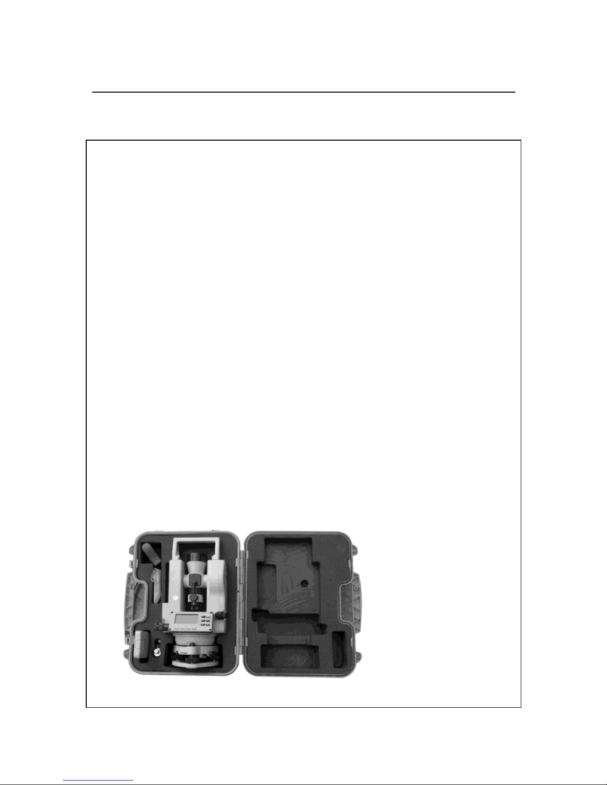
12) Place the instrument like the picture below:
13) Contact me if you got any problem.
Page 3

SMART MAX GEOSYSTEMS CO.,LTD
www.smartmaxgeosystems.com [email protected]
Contents
1. Description of All Parts………………………………1
1.1 Name of Parts ……………………………………………1
1.2 Display …………………………………………………3
1.3 Operation Key ………………………………………… 4
1.4 RS 232 ……………………………………………………6
2. Battery……………………………………………………6
2.1 Battery Replacement……………………………………6
2.2 Battery Recharging ………………………………………7
3. Measurement Preparation …………………………7
3.1 Instrument Setting Up……………………………………7
3.2 Instrument Leveling………………………………………7
3.3 Centering with Optical Plummet…………………………9
3.4 Eyepiece Adjustment and Object Sighting………………9
3.5 Power on ………………………………………………10
3.6 Power off………………………………………………10
4. Angle Measurement …………………………………11
4.1 Measuring Horizontal Angle Right and Vertical Angle …11
4.2 Switching Horizontal Angle Right/Left …………………12
4.3 Setting Horizontal Angle ……………………………13
4.4 Vertical Angle Percent Grade (%) Mode ………………14
4.5 Compasses (vertical angle) ……………………………15
4.6 Remeasuring Horizontal Angle…………………………15
Page 4

SMART MAX GEOSYSTEMS CO.,LTD
www.smartmaxgeosystems.com [email protected]
5. Distance Measurement………………………………17
6. Distance Measurement through the crossline in
the telescope………………………………………… 19
7. Laser Measurement…………………………………20
7.1 Orientation Measurement ……………………………… 20
7.2 Angle Designment……………………………………20
7.3 Zeith Measurement ……………………………………21
7.4 Level Measurement ……………………………………21
8. Parameter Setting Up………………………………22
8.1 Enter into Setting up Parameter ………………………22
8.2 Setting up Parameter ……………………………………23
9. Check & Adjustment………………………………24
9.1 Check & Adjustment of Plate Vial………………………24
9.2 Check & Adjustment of Circular Vial …………………26
9.3 Check & Adjustment of Optical Plummet………………26
9.4 Check & Adjustment of Inclination of Reticle…………28
9.5 Check & Adjustment of discrepancy between twice
collimation errors(C)………………………………… 29
9.6 Check & Adjustment of Vertical Index(i angle) ………30
9.7 Check & Adjustment of the laser confocal and coaxial… 31
10. Technical Index………………………………………33
11. Packing List …………………………………………35
12. Erorr Code Instruction ……………………………36
Page 5

SMART MAX GEOSYSTEMS CO.,LTD
www.smartmaxgeosystems.com [email protected]
1
1. Description of All Parts
1.1 Name of Parts
1.Telescope 2.Main body 3.Left Side Cover
4.Series No. 5.Optical Plummet 6.Circular Vail
7.Leveling Screw 8.Tribrach
9.Connection Knob on Tribrach 10.Soft Key
11.Display 12.Function Key 13.Plate Vial
14.Vertical Tangent Screw 15.Vertical Clamp Screw
16.Objective Lens
Page 6
SMART MAX GEOSYSTEMS CO.,LTD
www.smartmaxgeosystems.com [email protected]
2
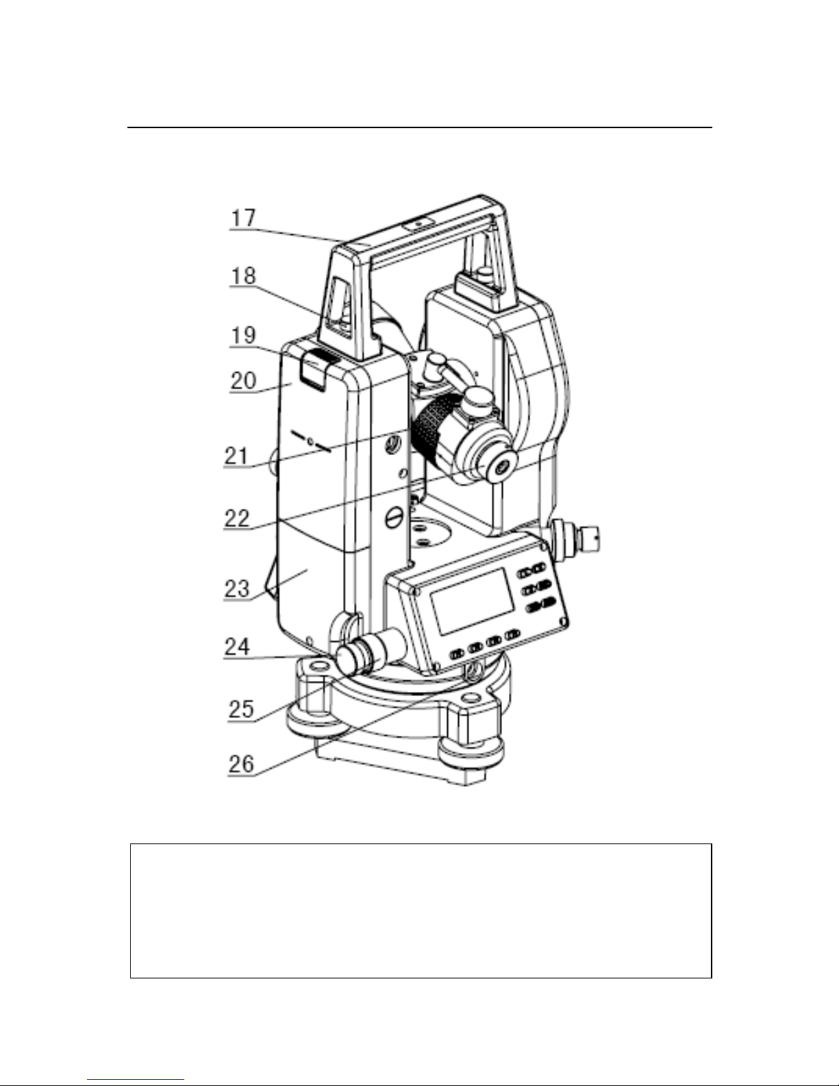
17. Handle 18.Handle Screw 19. Battery locking Lever
20. Battery 21. Grip 22. Eyepiece
23.Right Side Cover 24. Horizontal Tangent crew
25. Horizontal Clamp Screw 26.RS232 Port
Page 7
SMART MAX GEOSYSTEMS CO.,LTD
www.smartmaxgeosystems.com [email protected]
3
1.2Display
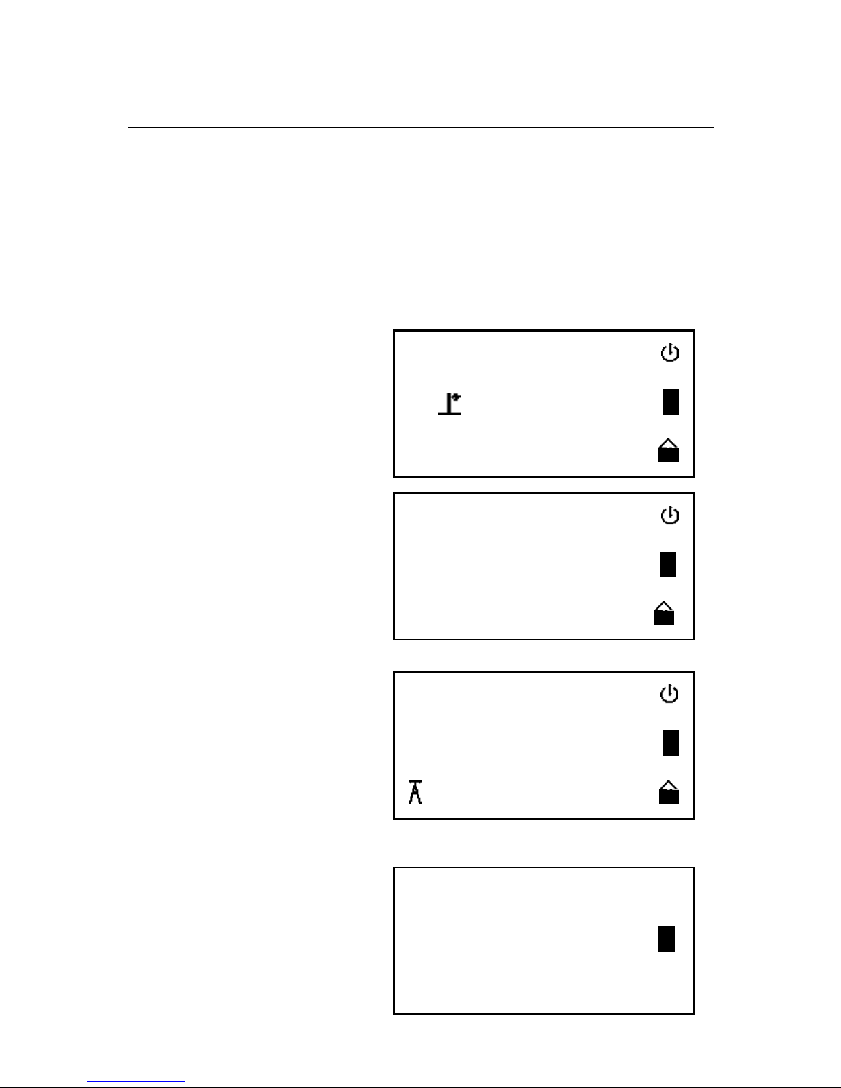
The figure LCD can display angle,characters,date and time,etc.
There are two modes on display:Measurement Mode & Menu
Mode.
Display(example):
① Angle
Measurement Mode
② Distance
Measurement Mode
③Remeasurement Mode
④Menu Mode
ANG 08-01-02 12:00
V : 81°54′21″
HR : 157°33′58″
08-01-02 12:00
n - 0 T-0
HR : 57°33′58″
08-01-02 12:00
S.E.T.-1
OFF
DIST 08-01-02 12:00
0.000 m
HR : 157°33′58″
Page 8
SMART MAX GEOSYSTEMS CO.,LTD
www.smartmaxgeosystems.com [email protected]
4
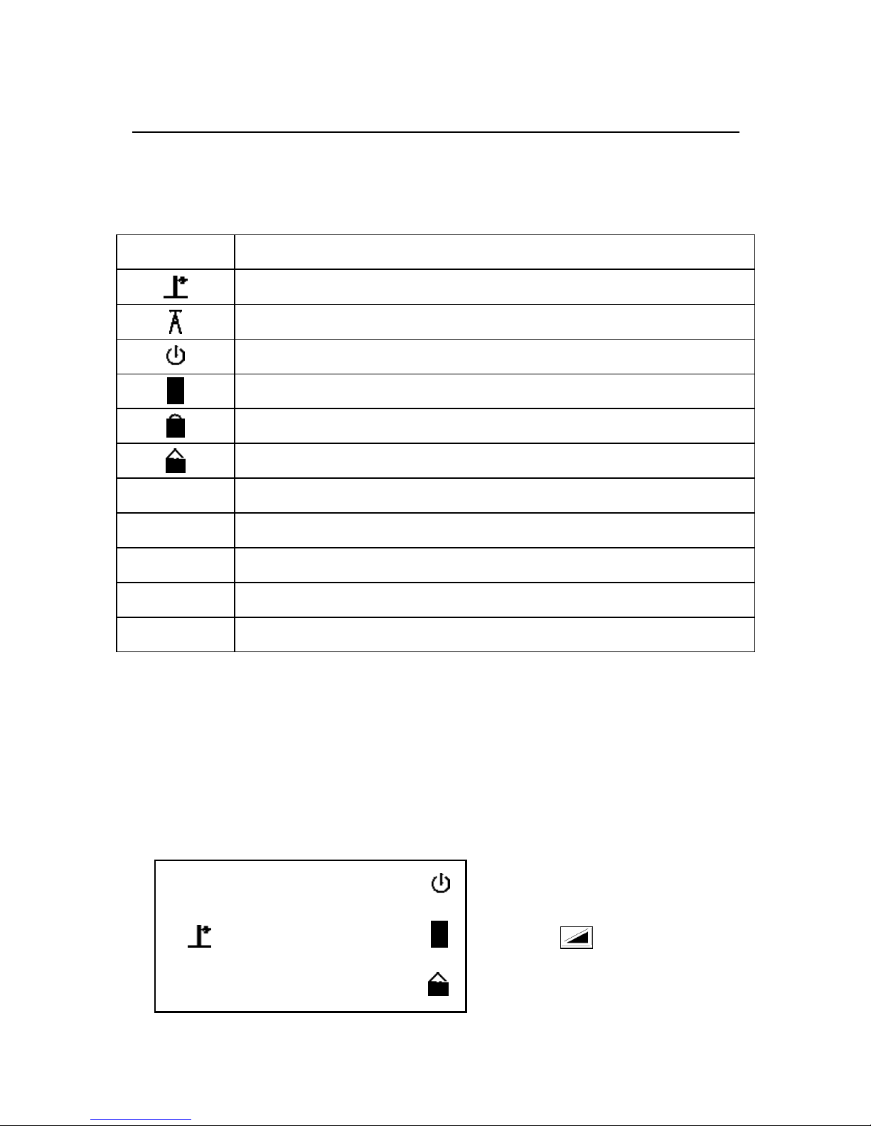
Symbol
Contents
Vertical compensation
Horizontal remeansure
Automatic Power off
Battery
Horizontal locked
Special Function,press ¤ twice,it will be disappeared
%
Gradient Display
b-OUT
Vertical angle is over the compensation
OUT
Slope is over ±100%
m
Meter unit
°′″
Set 360°as angle unit
1.3 Operation Key
The function of the soft key is different in different
measurement mode.
①Angle Measurement Mode
REP▲ Power
◆ ¤
ANG 08-01-02 12:00
V : 81°54′21″
HR :157°33′58″
Page 9

SMART MAX GEOSYSTEMS CO.,LTD
www.smartmaxgeosystems.com [email protected]
5
ANG▼ ENT
L/R HOLD % 0SET
Soft Key
Function
L/R
Switches R/L rotation of horizontal angle
HOLD
Hold the horizontal angle
%
Vertical angle percent grade(%) mode
0SET
Set horizontal angle as 0°00′00″
②Distance Measurement Mode
REP▲ Power
◆ ¤
ANG▼ ENT
SD HD VD TR
Soft Key
Function
SD
Enter into SD Measurement
HD
Enter into HD Measurement
VD
Enter into VD Measurement
TR
Enter into TR Measurement
DIST 08-01-02 12:00
0.000 m
HR : 157°33′58″
Page 10

SMART MAX GEOSYSTEMS CO.,LTD
www.smartmaxgeosystems.com [email protected]
6
③Special function Measurement mode(This will be valid only
in the Angle Measurement Mode)
Soft Key
Function
First press ¤, when it
display , press▲
Turn on /off laser alignment
First press ¤, when it
display , press▼
Turn on /off laser plummet
First press ¤, when it
display , press◆
Turn on /off LCD
First press ¤, when it
display , press ENT
Enter into Menu mode,press ENT
one more time will save and exit
1.4 RS232
RS232 is used to connect the Theodolite with computer or PC to
transfer measured data to computer or PC.
2. Battery
2.1 Battery Replacement
1. Battery Insert
Insert battery correctly. Check and
insert battery holder true to side into
the housing.
Page 11

SMART MAX GEOSYSTEMS CO.,LTD
www.smartmaxgeosystems.com [email protected]
7
2. Battery Removement
Remove battery and replace.
2.2 Battery Recharging
1. Insert recharger into battery’s hole.
2. Insert the plug of the recharger into 220V AC power supply. It
shows green light after finishing recharging.
3. Cut the power supply of the recharger and drew the battery out
from the recharger.
3. Measurement Preparation
3.1 Instrument Setting Up
1. Setting up the tripod.Pull out to
required length and tighten screws.
Page 12
SMART MAX GEOSYSTEMS CO.,LTD
www.smartmaxgeosystems.com info@smartmaxgeosystems.com
8
2. Place the INSTRUMENT onto
the tripod head. Tighten central fixing
screw of tripod.
3.2 Instrument leveling
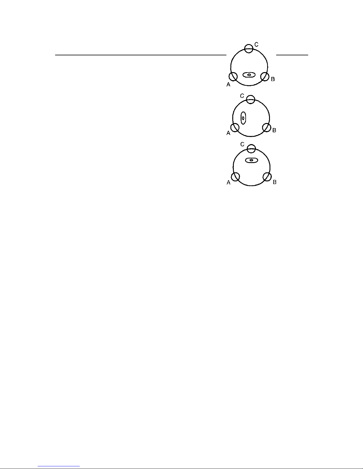
1.Level the instrument with circular vial
a. Turn the leveling screw A and B
to move the bubble in the circular vail.
The bubble is now located on a line
perpendicular to a line running through
the centers of the two leveling screw
being adjusted.
b. Turn the leveling screw C to bring
the bubble to the center of the circular
vail.
2. Level the instrument with plate vial
a. Rotate the instrument horizontally
by loosening the Horizontal Clamp
Screw and place the plate vial parallel with the line connecting
leveling screw A and B, and then bring the bubble to the center of
the plate vial by turning the leveling screws A and B.
Page 13
SMART MAX GEOSYSTEMS CO.,LTD
www.smartmaxgeosystems.com [email protected]
9
b. Rotate the instrument 90º (100g) around its vertical axis and
turn the remaining leveling screw or leveling C to center the
bubble once more.
c. Repeat the procedures 1& 2 for each 90º (100g) rotation of the
instrument and check the whether the bubble is correctly centered
for all four points.
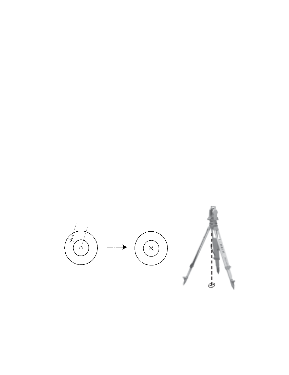
3.3 Centering by optical plummet
Adjust the eyepiece of the optical plummet telescope to your
eyesight. Slide the instrument by loosening the tripod screw,
place the point on the center mark of the optical plummet. Sliding
the instrument carefully not to rotate that allows you to get the
least dislocation of the bubble.
Note:Centering by foot screw first and then leveled-up by
tripod.
T/S Point
center
Page 14

SMART MAX GEOSYSTEMS CO.,LTD
www.smartmaxgeosystems.com [email protected]
10
3.4 Eyepiece Adjustment and Object Sighting
1. Sight the Telescope to the sky and rotate the eyepiece tube to
make the reticle clear.
2. Make the target image clear with the telescope focusing
screw. If there parallax when your eye move up, down or left,
right, that show the diopter of eyepiece lens or focus is not
adjusted well and accuracy will be influenced, so you should
adjust the eyepiece tube carefully to eliminate the parallax.
3.5 Power on
1.Leveling INSTRUMENT
2. Press the Power key (red
k
ey).
3. Turn telescope to
initial the INSTRUMENT.
Power
08-01-02 12:00
V 0 S.E.T.
ANG 08-01-02 12:00
V : 81°54′21″
Page 15

SMART MAX GEOSYSTEMS CO.,LTD
www.smartmaxgeosystems.com [email protected]
11
Confirm the battery is full,
if not so,please replace and
recharge the battery.
3.6 Power off
Press the Power key (red key).
4. Angle Measurement
4.1 Measuring Horizontal Angle Right and Vertical
Angle
Operation Procedure
Display
①Press ANG to enter into
Angle Measurement.
Aim at the first target A
测角 08-01-01 12:12 Φ
+垂直: 81°54′21″
水平右 : 157°33′58″
ANG 08-01-02 12:00
V : 81°54′21″
HR : 157°33′58″
Page 16

SMART MAX GEOSYSTEMS CO.,LTD
www.smartmaxgeosystems.com [email protected]
12
②Press 0SET to set
horizontal reading of target
A as 0°00′00″
③Aim at the second target
B. The required V/H angle
to target B will be
displayed.
★ Press ENT,the vertical and horizontal angle can be sent out
through RS232.
How to Collimate (Reference)
1. Point the telescope toward the light. Turn the diopter ring and
adjust the diopter so that the cross hairs are clearly observed.
(Turn the diopter toward you first and then backward to focus).
2. Aim the target at the peak of the triangle mark of the sighting
collimator. Allow a certain space between the sighting collimator
and yourself for collimating.
3. Focus the target with the focusing knob.If parallax is created
between the cross hairs and the target when viewing vertically or
horizontally while looking into the telescope, focusing is
incorrect or diopter adjustment is poor. This adversely affects
ANG 08-01-02 12:00
V : 81°54′21″
HR : 0°00′00″
ANG 08-01-02 12:00
V : 81°54′21″
HR : 57°33′58″
Page 17

SMART MAX GEOSYSTEMS CO.,LTD
www.smartmaxgeosystems.com [email protected]
13
precision in measurement or survey; eliminate the parallax by
carefully focusing and using diopter adjustment.
4.2 Switching Horizontal Angle Right/Left
Display
①Press ANG to enter into
Angle Measurement.
②Press L/R. The mode
Horizontal angle Right
(HR) Switches to (HL)
mode.
★ Press L/R to switch Right mode and Left mode.
★ Press ENT,the vertical and horizontal angle can be sent out
through RS232.
4.3 Setting Horizontal Angle
Setting by Holding the Angle
Operation Procedure
Display
ANG 08-01-02 12:00
V : 81°54′21″
HR :100°00′00″
ANG 08-01-02 12:00
V : 81°54′21″
HL :260°00′00″
Page 18
SMART MAX GEOSYSTEMS CO.,LTD
www.smartmaxgeosystems.com [email protected]
14
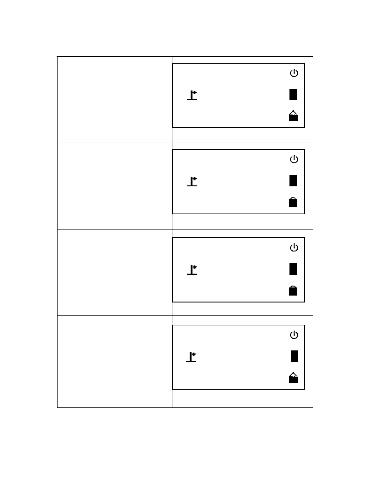
①Press ANG to enter into
Angle Measurement.
②Set the required
horizontal angle, using
Horizontal tangent
screw.Then press HOLD.
③Aim at the target which
need to be set up the angle
④Press the ENT to finish
holding the horizontal
angle.The display returns
back to normal angle
measurement mode.
ANG 08-01-02 12:00
V : 81°54′21″
HR :100°00′00″
ANG 08-01-02 12:00
V : 81°54′21″
HR :100°00′00″
ANG 08-01-02 12:00
V : 81°54′21″
HR :100°00′00″
ANG 08-01-02 12:00
V : 81°54′21″
HR :100°00′00″
Page 19

SMART MAX GEOSYSTEMS CO.,LTD
www.smartmaxgeosystems.com [email protected]
15
4.4 Vertical Angle Percent Grade (%) Mode
Operation Procedure
Display
①Press ANG to enter into
Angle Measurement.
②Press % to enter into
Slope Measurement.
★The display mode switches when pressing % key every time.
★While the measurement is carried out over ±45º(±100%)
from the horizontal,the display shows <OUT>.
4.5Compasses (vertical angle)(Refer to Parameter
Setting Up)
Vertical angle is displayed as shown below:
ANG 08-01-02 12:00
V : 81°54′21″
HR :100°00′00″
ANG 08-01-02 12:00
V : 50 %
HR :100°00′00″
Page 20

SMART MAX GEOSYSTEMS CO.,LTD
www.smartmaxgeosystems.com [email protected]
16
4.6 Remeasuring Horizontal Angle
Operation Procedure
Display
①Press REP to get into the
mode of Horizontal Angle
Remeasurement
08-01-02 12:00
n - 0 T-0
HR :57°33′58″
Page 21

SMART MAX GEOSYSTEMS CO.,LTD
www.smartmaxgeosystems.com [email protected]
17
②Aim at the Target A
Press 0SET(one time)to
set the reading of A as:
0°00′00″
③Aim at the Target B by
Horizontal Tangent and
Clamp Screws.
Press ENT(one time)to
remain the horizontal angle
and it will be saved
④Aim at the Target A
again
Press 0SET (one time)to
set the reading of A
as:0°00′00″.(It begins the
first remeasurement.)
⑤Aim at the Target B
again by Horizontal
Tangent and Clamp Screws
Press ENT(one time)to
remain and save the
n-1:the beginning of the angle
n-0: the ending of the angle
T-0 ~ T-8: the times of
remeasurement
08-01-02 12:00
n - 1 T-0
HR : 0°00′00″
08-01-02 12:00
n - 1 T-1
HR : 0°00′00″
08-01-02 12:00
n - 0 T-2
HR : 20°00′01″
Page 22

SMART MAX GEOSYSTEMS CO.,LTD
www.smartmaxgeosystems.com [email protected]
18
horizontal angle.
⑥Repeat step ④~⑤ to
do the required
remeasurement
⑦Measurement is over.
Press ANG to enter into
Angle Measurement.
★The remeasure times is limited,the Max is 9. It will show
“E-09” if more remeasurement done.Press REP and restart.
★When do remeasurement,it will display “E-08” if
︱Measured Value- Average Value ︱≥ 30″. Press REP and
restart.
5. DISTANCE MEASUREMENT
Please confirm the cable can be connected with our Distance
Meter before measurement.
Operation Procedure
Display
①Press to enter into
the mode of distance
DIST 08-01-02 12:00
0.000 m
HR :157°33′58″
ANG 08-01-02 12:00
V : 81°54′21″
HR :100°00′00″
ANG 08-01-02 12:00
V : 81°54′21″
HR : 100°00′00″
Page 23

SMART MAX GEOSYSTEMS CO.,LTD
www.smartmaxgeosystems.com [email protected]
19
measurement
②Aim at Prism center.
③Press L/R to start SD
Measurement while press
ENT to stop.
④Press HOLD to start
HD Measurement while
press ENT to stop.
⑤Press % to start VD
Measurement while press
ENT to stop.
⑥Press 0SET to start
Tracking Measurement
while press ENT to stop.
SD 08-01-02 12:00
22.000 m
HR :157°33′58″
HD 08-01-02 12:00
10.000 m
HR :157°33′58″
VD 08-01-02 12:00
3.000 m
HR :157°33′58″
DIST 08-01-02 12:00
20.00 m
HR :157°33′58″
Page 24

SMART MAX GEOSYSTEMS CO.,LTD
www.smartmaxgeosystems.com [email protected]
20
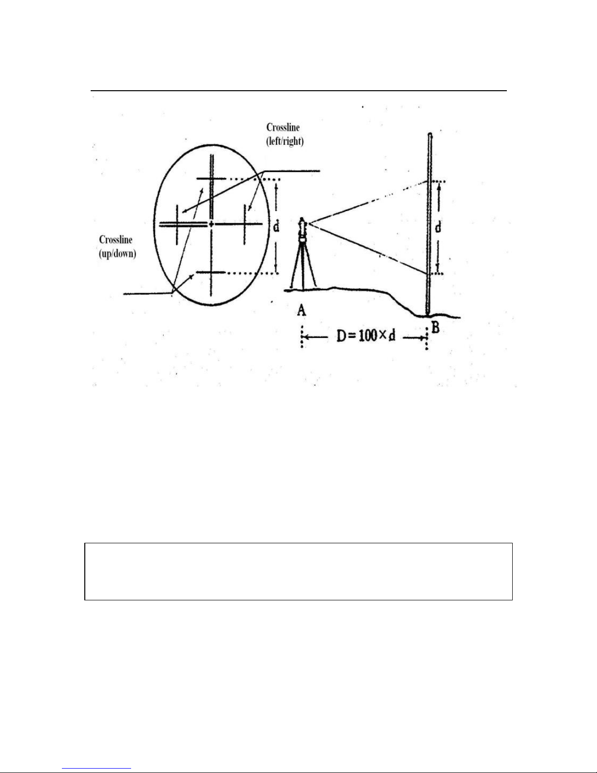
6. Distance Measurement through the
crossline in the telescope
Through the sightline (up/down or left/right) in the telescope
to measure the distance between the target and the
instrument.(Accuracy ≤ 0.4%D)
⑴ Place the instrument at point A,and place the leveling staff
at B.
⑵ Read the intercepted distance of the crossline(up/down or
left/right) on the leveling staff as “d”.
⑶The horizontal Distance between A and B is D(D= 100×d.)
Page 25
SMART MAX GEOSYSTEMS CO.,LTD
www.smartmaxgeosystems.com [email protected]
21
Note: 100 means the Stadia Proportion Constant of the
instrument. (But because of such a low accuracy,it can not be
used to measure distance which requires high accuracy.)
7. Laser Measurement
7.1 Orientation Measurement
Find out the other points on the line of the two known
points ,which should be based on the known two points,this is
Attention:Please don’t watch the laser with eyes directly,
when it is turned on!
Page 26

SMART MAX GEOSYSTEMS CO.,LTD
www.smartmaxgeosystems.com [email protected]
22
Laser Orientation Measurement.
Steps as bellows:
1.Leveling the instrument, then power on.
2.Aim at the target through the horizontal Tangent & Clamp
Screws.Turn on the laser.The other points can be found out with a
board which can make the laser focus together.
7.2 Angle Designment
Angle Designment is based on the line of two points,then
design a horizontal angle according with the requirement.
Steps as bellows:
1.Leveling the instrument, then power on.This must be done on a
fiducial point.
2.Aim at another fiducial point carefully,and set the horizontal
angle as 0°00′00″.
3.Move the telescope to make the horizontal angle be the required
value.Turn the laser on,the laser and the fiducial line will make
up an angle.
7.3 Zeith Measurement
Set a point as a standard, the laser will be set up vertically,this is
Zeith Measurement.
Steps as bellows:
Page 27

SMART MAX GEOSYSTEMS CO.,LTD
www.smartmaxgeosystems.com [email protected]
23
1.Take away the eyepiece, fit on the diagonal eyepiece, and
locked.
2. Leveling the instrument, then power on.This must be done on a
fiducial point.
3. Circumgyrate the telescope to make the vertical angle to
0°00′00″,turn the laser on.Then move the foucsing screw to make
the facula minimum,loosenthe horizontal clamp screw, move the
telescope,the geometry center of the facula’s movig track is the
Vertical Direction.
7.4 Level Measurement
1. Leveling the instrument, then power on..
2. Lock the telescope after it is on the horizontal direction,aim at
the target carefully.Turn on the laser,the red laser line can be used
as level line.
8. Parameter Setting Up
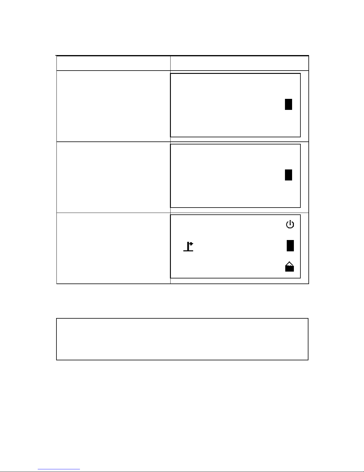
8.1 Enter into Setting up Parameter
Operation Procedure
Display
①Press ¤ and then press
ENT when in the angle
measurement mode to
08-01-02 12:00
SET-1
OFF
Page 28
SMART MAX GEOSYSTEMS CO.,LTD
www.smartmaxgeosystems.com [email protected]
24
enter into Menu Mode.
② Press ◆ to choose
parameter which need to
be set up.
(Continuous press)
③Press▲、▼ to set up
parameter.
(Continuous press)
④Press ENT to save.
8.2 Setting up the Parameters
①SET-0:Power off Automatically
ON---The instrument will power off automatically if there is no
08-01-02 12:00
SET-1
OFF
08-01-02 12:00
SET-1
ON
ANG 08-01-02 12:00
V : 81°54′21″
HR :100°00′00″
★When Setting up Parameter, press ¤ to escape back to
angle measurement.The modified won’t be saved.
Page 29

SMART MAX GEOSYSTEMS CO.,LTD
www.smartmaxgeosystems.com [email protected]
25
operation within 30 minutes
OFF--- Not automatically power off
②SET-1:Compensator
ON---Turn on the compensator
OFF---Turn off the compensator
③SET-2:Position 0(Vertical Angle)
ON ---Zeith is 0°,the Horizontal will be 90° when turn left and
it will be 270° when turn right.
OFF---Zeith is 90°,the Horizontal will be 0° when turn left
④SET-3:Minimum Reading
1---Minimum Reading is 1"
5---Minimum Reading is 5"
10---Minimum Reading is 10"
20---Minimum Reading is 20"
⑤SET-4:Angle Unit
1---Set 360° as angle unit
2---Set 6400mil as angle unit
3---Set 400g as angle unit
Page 30

SMART MAX GEOSYSTEMS CO.,LTD
www.smartmaxgeosystems.com [email protected]
26
9. Check & Adjustment
9.1 Check & Adjustment of Plate Vial
Check
① Rotate the instrument horizontally by loosening the Horizontal
Clamp Screw and place the plate vial parallel with the line
connecting leveling screw A and B, and then bring the bubble to
the center of the plate vial by turning the leveling screws A and B.
②Rotate the instrument 180°(200g)around its vertical axis.
Observe the bubble of plate vial. Fellow the steps below to adjust
it if the bubble is not in the center.
Remarks: SET-5 、 SET-6 、 SET-7 、 SET-8 、
SET-9means year,month,day,hour,minute(This is
optional )
Page 31

SMART MAX GEOSYSTEMS CO.,LTD
www.smartmaxgeosystems.com [email protected]
27
Adjustment
① If the bubble of the plate vial moves from the center, bring it
half way back to the center by adjusting the leveling screw, which
is parallel to the plate vial. Correct the remaining half by
adjusting the screw of plate vial with adjusting pin.
② Confirm whether the bubble does is in the center by rotating
the instrument 180º.If not, repeat step ①.
③ Turn the instrument 180°(200g)and adjust the third screw to
center the bubble in the vial.
Half of deflection
Page 32

SMART MAX GEOSYSTEMS CO.,LTD
www.smartmaxgeosystems.com [email protected]
28
9.2 Check & Adjustment of Circular Vial
Check
No adjustment is necessary
if the bubble of the circular
vial is in the center after
inspection and adjustment
of the plate vial.
Adjustment
If the bubble of the circular
vial is not in the center, bring
the bubble to the center by
using the adjusting pin to adjust
two bubble-adjusting screws.
9.3 Check & Adjustment of Optical Plummet
Check
①Set the instrument on the tripod and place a piece of white
paper with two perpendicular lines, then intersect drawn on it
directly under the instrument. Adjust the leveling screws so that
the center mark of the optical plummet coincides with the
intersection point of the cross on the paper.
Circular vial
Bubble-adjusting screw
Page 33

SMART MAX GEOSYSTEMS CO.,LTD
www.smartmaxgeosystems.com [email protected]
29
②Rotate the instrument around the horizontal axis 180°(200g)
observe whether the center mark position coincides with the
intersection point of the cross. If the center mark always
coincides with intersection point, no adjustment is necessary.
Otherwise, the following adjustment is necessary.
Adjustment
①Take off protective cover of the optical plummet, you may see
four adjusting screws. Adjust four adjusting screws.
②Move woodscrew to make the center of optical plummet
coincides with ground point.
③Rotate the instrument around the vertical axis 180°(200g)
observe whether the center mark position coincides with the
intersection point of the cross. If the center mark always
coincides with intersection point, no adjustment is necessary.
Adjusting Screw (4 pcs)
Page 34

SMART MAX GEOSYSTEMS CO.,LTD
www.smartmaxgeosystems.com [email protected]
30
Otherwise, repeat steps above mentioned.
9.4 Check & Adjustment of Inclination of Reticle
Check
①Set the instrument on a tripod and level it.
②Aim at target A with telescope(One point, 50m away).
③Observe point A moves along the vertical line of the reticle or
not by moving telescope up and down.. If so, no adjustment is
necessary. If not so, then need to adjust the reticle.
Adjustment
① Remove the eyepiece cover to expose the four reticle adjusting
screws.
Page 35

SMART MAX GEOSYSTEMS CO.,LTD
www.smartmaxgeosystems.com [email protected]
31
② Loosen the four reticle adjusting screws uniformly with an
adjusting pin. Rotate the reticle around the sight line and align the
vertical line of the reticle with point A. Tighten the reticle
adjusting screws.
③ Repeat the inspection and adjustment to see if the adjustment
is correct.
9.5 Check & Adjustment of discrepancy between
twice collimation errors(C)
Eyepiece
Reticle adjusting screws
Reticle adjusting screws
Note:Remember to check the index of the instrument after
adjusting.
Page 36

SMART MAX GEOSYSTEMS CO.,LTD
www.smartmaxgeosystems.com [email protected]
32
Check
① Set the instrument on a tripod and level it.
② Aim at cross line of the reticle of the collimator or a target
away. Observe left position and right position.
③ Calculate difference after getting horizontal angle reading (left
position) HI and(right position)HR
C =( HI – HR ± 180°)/2
If C ≤ 8",no adjustment is necessary;If C > 8",fellow these
steps to adjust it.
Adjustment
① Rotate fine motion screw in the right position and make the
reading is HR + C.
② Remove the eyepiece cover to adjust two adjusting screws,
which makes reticle coincides
with cross line of collimator or one target away.
③ Repeat check and adjustment until C ≤ 8".
C =( HI – HR ± 180°)/2
9.6 Check & Adjustment of Vertical Index Difference
( i angle)
(Inspect the item after finishing the inspection and
adjustment of section 9.4 and 9.5.)
Check
① Set the instrument on a tripod and level it.
Page 37

SMART MAX GEOSYSTEMS CO.,LTD
www.smartmaxgeosystems.com [email protected]
33
② Sight object A in left position and read the Vertical angle value
VI. Rotate the telescope. Sight object B in right position and read
the Verticail angle value VR.
③ Calculating, i=(VI+VR-360°)/2
④If i ≤10",no adjustment is necessary. If i >10", adjust it.
Adjustment
(Please adjust through the software if the differences between
the index is too big.)
Operation Procedure
Display
① Keep to press L/R to
power on until right screen
occurs. Loose L/R
② Rotate telescope and
make vertical angle
passing 0.
Enter into the mode of V
ANGLE 0 SET
V 0 S.E.T.
S.E.T.-301
V: 90°00′00″
STEP - 1
V: 270°00′00″
STEP - 2
Page 38

SMART MAX GEOSYSTEMS CO.,LTD
www.smartmaxgeosystems.com [email protected]
34
③Aim at target (left
position). Press ENT
④ Aim at target (right
position).Press ENT
Power on automatically.
⑤Finish adjustment.
Repeat,if not within
standard.
9.7 Check & Adjustment of the laser confocal and
coaxial
(This step was done after finishing the inspection and
adjustment of Item 9.4 and 9.5)
Laser confocal
Send the laser after aiming at the target,and then check the
facula’s diameter.It should be minimum.If it is not,loose the
screw on the laser pedestal,and move the pedestal until the facula
be smallest.
Laser coaxial
The crossline should be in superposition with the facula after
aiming at the target.Make the facula in the center of the crossline
through the four screws on the pedestal.(as the picture below)
1
Page 39

SMART MAX GEOSYSTEMS CO.,LTD
www.smartmaxgeosystems.com [email protected]
35
2 4
3
10. Technical Index
Telescope
Image Erect
Magnification 30×
Effective aperture 47mm
Resolving power 3.75″
Field of view 1°30′(26m/1000m)
Minimum focus 1m
Stadia ratio 100
Up,tighten screw 1,relax screw 3
Down,tighten screw 3,relax screw 1
Left,tighten screw 4,relax screw 2
Right,tighten screw 2,relax screw 4
Page 40

SMART MAX GEOSYSTEMS CO.,LTD
www.smartmaxgeosystems.com [email protected]
36
Sight distance precision ≤0.4%D
Tube length 162mm
Angle Measurement
Measuring method photoelectric detection
by incremental encoder
Diameter of circle 79mm
Minimum reading 1″, 5″, 10″ , 20″Selectable
Measuring unit 360°, 400gon, 6400mil Selectable
Vertical angle0° Zenith0°, Horizontal0°Selectable
Accuracy 2″、5″、10″Selectable
Vial
Plate vial 30″/2mm
Circular vial 8′/2mm
Compensator
System Liquid-electric detection
Compensation range ±3′
Resolving power 1″
Optical Plummet
Image Erect
Magnification 3×
Focusing range 0.3m~∞
Field of view 5°
Display
Type LCD,Four lines,digital
Data Communication
Port RS-232C
Page 41

SMART MAX GEOSYSTEMS CO.,LTD
www.smartmaxgeosystems.com [email protected]
37
On-board Battery
Power resource Rechargeable Ni-H battery
Voltage DC6V
Operation time BDC 1800mAh(about 20 hours)
Laser
Length of the wave 635nm
Power 10mW
Effective range(during daytime) 150m
Position error with the sight ≤5″
Power DC3.3V
Working temperature -10℃~+45℃
Operation Environment
Operating temperature -20℃~+45℃
Size & weight
Dimension 180mm×166mm×355mm
Weight 6.5kg
11. Packing List
Instrument
1pc
Battery
2pcs
Page 42

SMART MAX GEOSYSTEMS CO.,LTD
www.smartmaxgeosystems.com [email protected]
38
Recharger
1pc
Plummet
1pc
Tool bag
1pc
Carrying case
1pc
Operator manual
1pc
12. Error Code Instruction
E-301 Memory Card-Error
E-302 VJ767-Error
Page 43

SMART MAX GEOSYSTEMS CO.,LTD
www.smartmaxgeosystems.com [email protected]
39
E-303 HJ767-Error
E-304 HY767-Error
E-305 HJ767-Error AND HY767-Error
E-108 Compensator-Error
E-08 Remeasurment
︱Measured Value- Average Value︱> 30″
E-09 Remeasurement times more than 9
 Loading...