

Page 1
1
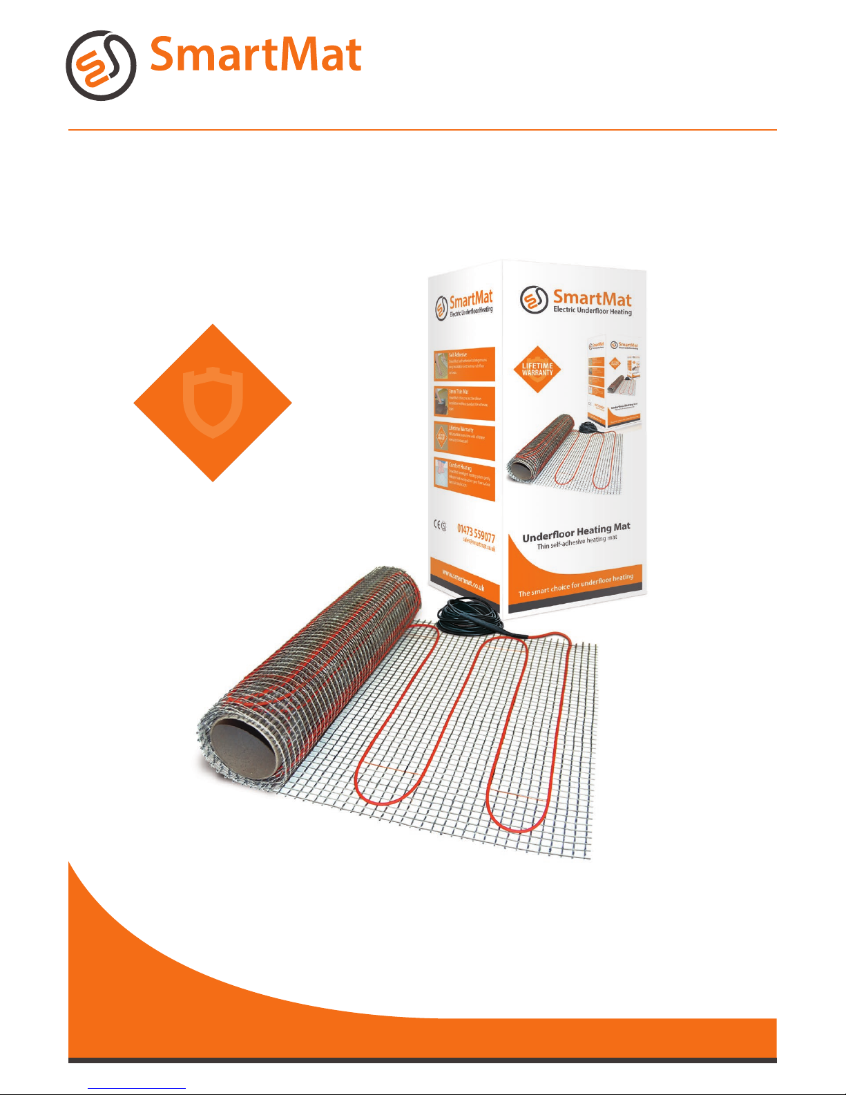
Electric Underfloor Heating
INSTALLATION MANUAL
Mat 10 0w/150w/200w
Before you begin installing, read through these instructions
carefully and check that you have all the components required.
www.smartmat.co.uk
01473 559077
LIFETIME
WARRANTY
Page 2

2
Introduction
Important notes, please read carefully before proceeding with installation
The SmartMat brand
Thank you for choosing the SmartMat underoor
heating mat from our range of electric underoor
heating solutions.
The SmartMat range has been manufactured to
surpass all current industry standards and comes
with a lifetime warranty.
SmartMat underoor heating mat
The SmartMat underoor heating mat has a selfadhesive bre glass backing mesh with an ultra-thin
twin conductor 3mm heating cable pre attached,
ensuring minimal increase to the existing oor
height. The function of the matting system is to
provide a warm oor.
Superior product design ensures a speedy
installation with an even heat across the complete
oor surface, whilst allowing unlimited adjustment
of the heating element to suit irregular formats.
The SmartMat matting system is available in three
output types:
Tools needed for installation
You will require the following items to install and
test the oor warming systems.
• Tape measure, drawing pad and pencil
• Utility knife, scissors
• Cable strippers, screw driver
• Resistance tester (multimeter), insulation
resistance tester
You will also need the appropriate tools and materials
to install your nished oor surface; these will probably
include products like self-levelling compound,
insulated backer board, notched tile trowel and various
other tools and materials for your
specic project.
Dos & Don’ts
Do
Carefully read this instruction manual before starting
your installation and follow the testing procedure on
page 7. Throughout your installation:
• Take time to plan your mat layout considering all
obstacles e.g. kitchen cupboards, bathroom sinks etc.
Ensure the mat will fit before laying.
• Use flexible tile adhesives and grouting materials.
• Ensure the floor sensor thermostat is inserted within
the flexible tube provided and installed between two
heating elements, with the floor end of the flexible
tube effectively sealed (to ensure easy removal of floor
sensor if required after installation). See page 3.
• Maintain a minimum of 50mm between the heating
element runs.
• Take care not to damage the heating element and cold
tail whilst tiling.
• Ensure all the orange heating element is covered
with a flexible self-levelling compound or flexible tile
adhesive.
• Make certain there are no air gaps underneath tiled
areas or between heating element runs.
• Ensure the floor surface is prepared correctly before
installation. See note on page 4.
• When using more than one mat from a single supply,
cold tails must be connected in parallel.
Don’t
• Cut or shorten the orange heating cable.
• Cross or touch the orange heating cables together.
Switch on your under floor heating system for a
minimum of 7 days after tiling to allow correct curing
of tile adhesives and grouts.
• Connect the heating element to the power supply
whilst still rolled up.
• Leave rolled up surplus sections of mat under kitchen
units or bath spaces.
• Commence installation of your floor surface before
testing your mat. See page 7.
• Tile over damaged or twisted cables.
• Install under kitchen units or permanent fixtures such
as baths
100 watts per m
(for use with timber
oor substrates e.g.
plywood etc).
150 watts per m
(for use with concrete
oor substrates e.g. sand
cement screed, insulated
backer boards etc).
200 watts per m
(for use where a
higher wattage
output is required e.g.
conservatory).
Page 3
3
Electrical Requirements
100 watt/150 watt/200 watt
Please follow these instructions carefully.
If you require assistance prior to or during
your installation please call our helpline on
01473 559077
Electrical requirements
Before installing the SmartMat you should make
allowance for the electrical connections.
The SmartMat system requires a mains voltage
230/240V and must be connected in accordance
with
the current IEE regulations and building regulations
part ‘P’ approved document.
For areas up to 30m (SmartMat 100w), areas up
to 20m (SmartMat 150w) or areas up to 15m
(SmartMat 200w) power connection can be
provided through a 13A switched spur outlet/
combined RCD spur outlet.
For areas larger than the above, a dedicated circuit
should be installed from the local consumer unit.
If you are required to switch greater electrical
load than 15A, a suitably sized thermostat or
electrical contactor MUST BE INSTALLED. If in
doubt please call our helpline on 01473 559077.
It is a requirement that all SmartMat systems are
protected by a 30ma RCD earth trip either at the
consumer unit or by a combined RCD spur outlet.
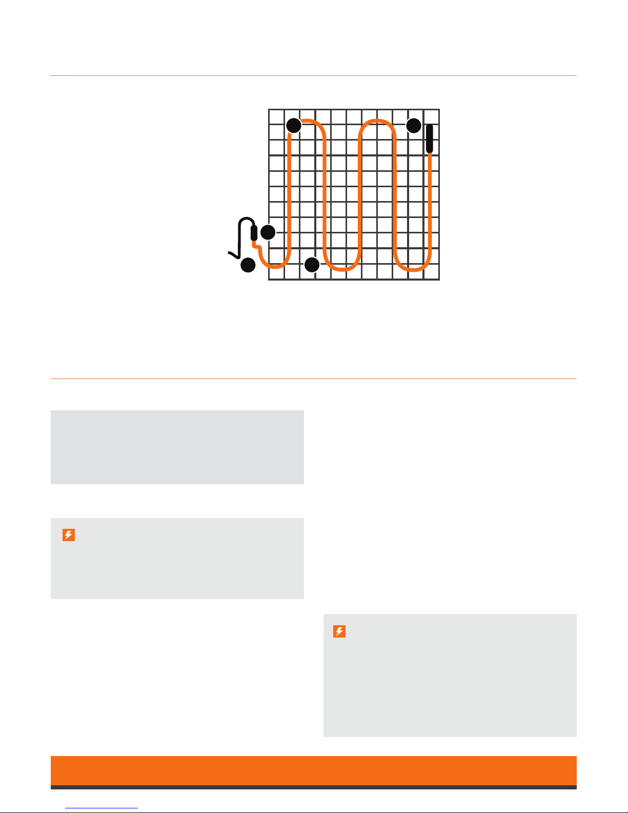
Contents of SmartMat Underoor Mat
A
E
C
D B
Important Note
When designing your electrical installation, you
should always consult an electrician regarding
your requirements.
Important Note
When installing in a bathroom or other wet areas
the thermostat must be located outside Zone 2
(0.6m from any wet appliance, e.g. shower, sink etc)
or outside the wet area, ideally on the opposite
face of the wall. The SmartMat must be earth
bonded in accordance with current IEE regulations.
• Heating mat
• Sensor tube
• Installation instructions
• Warranty
This manual contains all the
information you will
need about the
SmartMat underoor heating mat.
Please take time to study the
information thoroughly
before you
attempt to install this product.
A Heating element
B Fibreglass backing mesh
C Factory made cold tail joint
D Cold tail power lead
E End termination joint
Page 4
4
Installation Instructions
100 watt/150 watt/200 watt
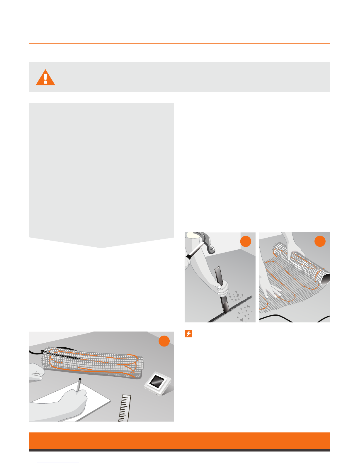
Step 1
Draw a layout of your room including all obstacles
e.g. toilet, sink etc, (use the oor plan grid on
page 10) then determine the required oor area
to be heated. Decide a suitable position for the
thermostat (start point) then sketch the proposed
SmartMat layout to ensure the heated area is
completely covered whilst using all of your mat (see
mat planner notes on page 6).
Step 2
Directly below the electrical connection point install
a 10mm exible tube (provided with each SmartMat)
–
you may have to channel a groove to allow the
exible tube to remain ush with the existing oor.
The oor sensing probe is to be installed into the
exible tube to monitor the oor temperature.
Ensure the tube is installed to allow easy replacement
of the sensor probe (in case the sensor fails) and
positioned between two heating elements.
The exible tube in the oor should be sealed to
prevent adhesive or self-levelling compound
entering the tube.
Ensure your SmartMat is correctly sized before you unpack the product.
Call 01473 559077 if you have any questions.
Note
The oor should now be prepared ready for the
SmartMat installation.
All loose particles should be removed and the
oor thoroughly cleaned and treated with any
proprietary sealants as normally required for
your nished oor.
If your existing oor has a bitumen or asphalt
surface, it must either be removed or covered
with a thin exible self-levelling compound, tile
backer board or water resistant timber.
If you are installing insulated tile backing
boards, do so in accordance with the
manufacturer’s instructions.
Now check the resistance of the mat
(see page 7 for details)
Steps 3 & 4
Remove the plastic outer cover from the SmartMat.
Position at the start of your matting plan with
the
cold tail (power cable) at the electrical connection
and positioned in to a low level electrical back box.
Ensure the separate thermostat oor sensor cable is
inserted into the pre-installed 10mm exible tube
and returned to the low level electrical back box.
1
2
3
Page 5
5
Installation Instructions
100 watt/150 watt/200 watt
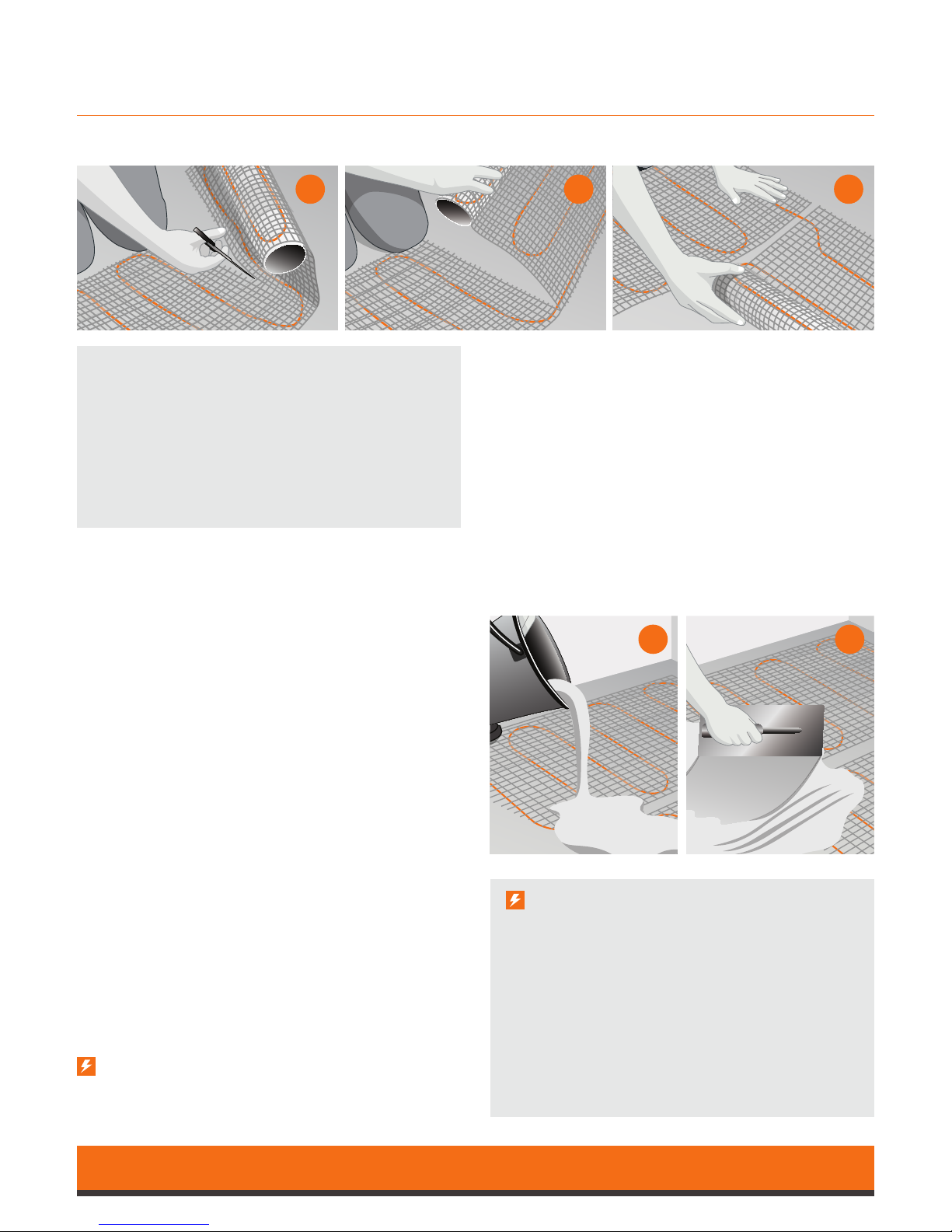
Steps 5, 6 & 7
When you have reached the end of the mat run,
carefully cut the grey backing mat in between the
two orange cables (do not cut the orange cable)
and turn the mat to its new position. Ensure the
cable remains a minimum of 50mm apart.
Once the mat is turned and secured, continue
this
process until all of the mat is used. Then check the
complete matting area is securely xed to the oor.
Check the resistance of the mat again (see
page 7 for details) to make sure damage
hasn’t occurred during the installation process.
Note
In some instances it may be necessary to remove
the orange cable from the grey backing mat.
Ensure the cables are not laid in areas where
xed appliances could be positioned e.g.
underneath sink basins or toilet pans.
Important Note
After the nished oor covering has been laid,
perform the following tests (see page 7 for details):
• Insulation resistance test
• Heating cable resistance test
• Thermostat oor sensor resistance test
Record your ndings in the test & commission
form enclosed in the mat box.
Register your warranty online at:
www.smartmat.co.uk/warranty
Steps 8 & 9
The mat can now be covered with either a exible
tile adhesive or exible self-levelling compound.
Check there are no air pockets then carefully spread
the exible tile adhesive or self-levelling compound
until all mat areas and heating cables are covered.
You can tile directly over the mat. Carefully apply the
exible tile adhesive with a notched trowel ensuring
each tile is securely xed, and all mat and cable
areas are completely covered with the adhesive.
5 6 7
8 9
Steps 3 & 4 (continued)
The factory made cold tail joint must be positioned in
the oor area. Once the mat cold tail (power cable) and
thermostat oor sensor probe have been positioned
(ensure the sensor probe is situated between two
heating elements) you can start to lay your mat.
Following your previously drawn mat layout, ensure
the mat is placed on the oor with the adhesive side
down. Unroll your mat until you reach the end of
your rst run.
Page 6
6
Mat Planning Examples
100 watt/150 watt/200 watt
Please follow these instructions
carefully. If you require assistance
prior to or during your installation
please call our helpline on
01473 559077.
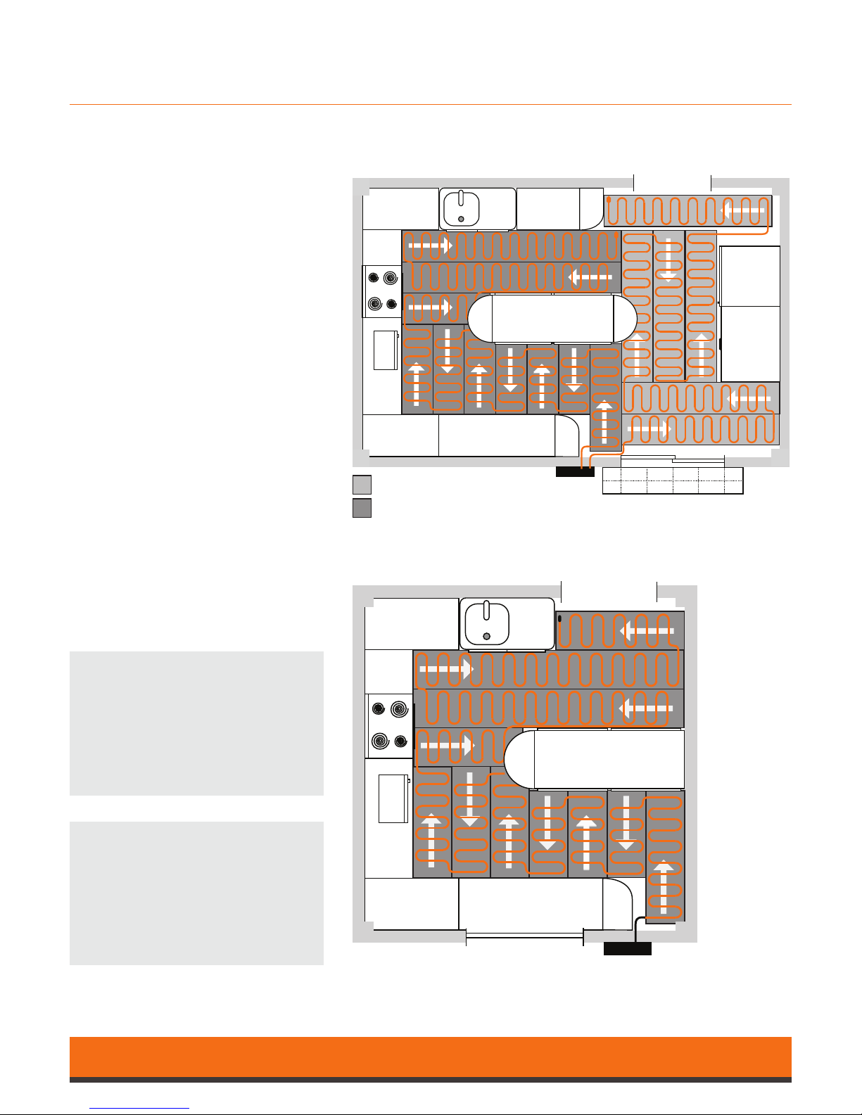
Layout of second mat
Layout of rst mat
Plan using two mats
Plan using one mat
Planning your mat
When planning your SmartMat,
ensure you cover as much of your free
oor area as possible:
• never install your heating cables any
less than 50mm apart.
• never cut your heating cable.
• never remove any pre-manufactured
cable joints or end seal joints.
When installing two or more mats
within the same area always ensure
the cold tail (power cables) are
returned to the thermostat power
connection and are wired in parallel,
never wire your SmartMat in series,
and always check your SmartMat
is thoroughly adhered to the oor
before tiling.
Timber substrates should be prepared
as required by tiling guide lines, for
example bracing of a timber oor with
WBP or tile backer board.
Note
• Sketch your oor plan using the
grid on pages 10 & 11
• Calculate your Total Load on
page 9
Page 7
7
Testing & Commissioning
100 watt/150 watt/200 watt
Warranty Validation
To validate your lifetime online warranty registration you must perform the insulation resistance
test, the heating cable resistance test and the sensor resistance test three times during the
installation process.
1. Before you lay the SmartMat.
2. After you have laid your SmartMat and before you cover your SmartMat.
3. After your nished oor has been laid.
This information must then be recorded on your commissioning record form (enclosed in the mat box).
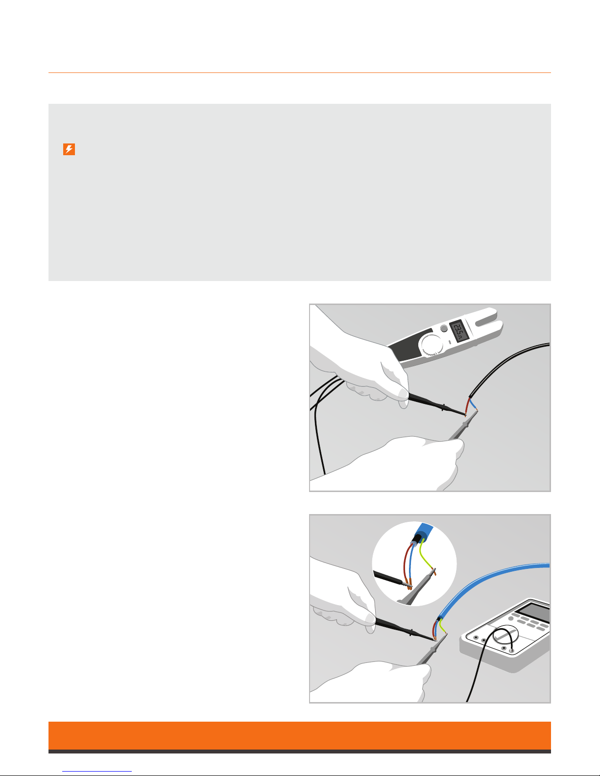
Heating Cable Resistance Test
This test is carried out to prove continuity of the
heating element. A low resistance ohm meter
should be used (ie Multimeter on ohm setting),
connect your meter on to the brown and blue mains
lead and conrm resistance value matches that
quoted on your specication label on the cable cold
lead joint.
Floor Cable Resistance Test
See Heating Cable Resistance Test and repeat with
oor sensor cable.
Insulation Resistance Test
This test is performed to measure the insulation
resistance between conductors and ensures the
cable insulation is not damaged. A low resistance
reading indicates a damaged cable and must be
repaired or replaced.
The insulation resistance tester should be connected
between the conductors (blue and brown cables)
and the earth (yellow/green cable). The meter
should
record a high resistance value e.g. above 100
Meg ohms.
Page 8

8
Product Specications
100 watt/150 watt/200 watt
100W
Quick Find Part Code Coverage Length Width Wattage Resistance +9/-4%
8488 SmartMat 100-1 1.00m² 2.0m 0.5m 100w 529.00 Ω
8489 SmartMat 100-1.5 1.50m² 3.0m 0.5m 150w 352.67 Ω
8490 SmartMat 100-2 2.00m² 4.0m 0.5m 200w 264.50 Ω
8491 SmartMat 100-2.5 2.50m² 5.0m 0.5m 250w 211.60 Ω
8492 SmartMat 100-3 3.00m² 6.0m 0.5m 300w 176.33 Ω
8493 SmartMat 100-3.5 3.50m² 7.0m 0.5m 350w 151.14 Ω
8494 SmartMat 100-4 4.00m² 8.0m 0.5m 400w 132.25 Ω
8495 SmartMat 100-5 5.00m² 10.0m 0.5m 500w 105.80 Ω
8496 SmartMat 100-6 6.00m² 12.0m 0.5m 600w 88.17 Ω
8497 SmartMat 100-7 7.00m² 14.0m 0.5m 700w 75.57 Ω
8498 SmartMat 100-8 8.00m² 16.0m 0.5m 800w 66.13 Ω
8499 SmartMat 100-9 9.00m² 18.0m 0.5m 900w 58.78 Ω
8500 SmartMat 100-10 10.00m² 20.0m 0.5m 1000w 52.90 Ω
8501 SmartMat 100-12 12.00m² 24.0m 0.5m 1200w 44.08 Ω
150W
Quick Find Part Code Coverage Length Width Wattage Resistance +9/-4%
8502 SmartMat 150-1 1.00m² 2.0m 0.5m 150w 352.67 Ω
8503 SmartMat 150-1.5 1.50m² 3.0m 0.5m 225w 235.11 Ω
8504 SmartMat 150-2 2.00m² 4.0m 0.5m 300w 176.33 Ω
8505 SmartMat 150-2.5 2.50m² 5.0m 0.5m 375w 141.07 Ω
8506 SmartMat 150-3 3.00m² 6.0m 0.5m 450w 117.56 Ω
8507 SmartMat 150-3.5 3.50m² 7.0m 0.5m 525w 100.76 Ω
8508 SmartMat 150-4 4.00m² 8.0m 0.5m 600w 88.17 Ω
8509 SmartMat 150-5 5.00m² 10.0m 0.5m 750w 70.53 Ω
8510 SmartMat 150-6 6.00m² 12.0m 0.5m 900w 58.78 Ω
8511 SmartMat 150-7 7.00m² 14.0m 0.5m 1050w 50.38 Ω
8512 SmartMat 150-8 8.00m² 16.0m 0.5m 1200w 44.08 Ω
8513 SmartMat 150-9 9.00m² 18.0m 0.5m 1350w 39.19 Ω
8514 SmartMat 150-10 10.00m² 20.0m 0.5m 1500w 35.27 Ω
8515 SmartMat 150-12 12.00m² 24.0m 0.5m 1800w 29.39 Ω
Page 9

9
200W
Quick Find Part Code Coverage Length Width Wattage Resistance +9/-4%
8516 SmartMat 200-1 1.00m² 2.0m 0.5m 200w 264.50 Ω
8517 SmartMat 200-1.5 1.50m² 3.0m 0.5m 300w 176.33 Ω
8518 SmartMat 200-2 2.00m² 4.0m 0.5m 400w 132.25 Ω
8519 SmartMat 200-2.5 2.50m² 5.0m 0.5m 500w 105.80 Ω
8520 SmartMat 200-3 3.00m² 6.0m 0.5m 600w 88.17 Ω
8521 SmartMat 200-3.5 3.50m² 7.0m 0.5m 700w 75.57 Ω
8522 SmartMat 200-4 4.00m² 8.0m 0.5m 800w 66.13 Ω
8523 SmartMat 200-5 5.00m² 10.0m 0.5m 1000w 52.90 Ω
8524 SmartMat 200-6 6.00m² 12.0m 0.5m 1200w 44.08 Ω
8525 SmartMat 200-7 7.00m² 14.0m 0.5m 1400w 37.79 Ω
8526 SmartMat 200-8 8.00m² 16.0m 0.5m 1600w 33.06 Ω
8527 SmartMat 200-9 9.00m² 18.0m 0.5m 1800w 29.39 Ω
8528 SmartMat 200-10 10.00m² 20.0m 0.5m 2000w 26.45 Ω
8529 SmartMat 200-12 12.00m² 24.0m 0.5m 2400w 22.04 Ω
Product Specications
100 watt/150 watt/200 watt
Calculator
Calculate your total load
......................................................................................................................
.....................................................................................................................
......................................................................................................................
......................................................................................................................
......................................................................................................................
......................................................................................................................
......................................................................................................................
Total Load ................................
Page 10

10
Floor plan Sketch
Calculate your total heat area
Page 11
11
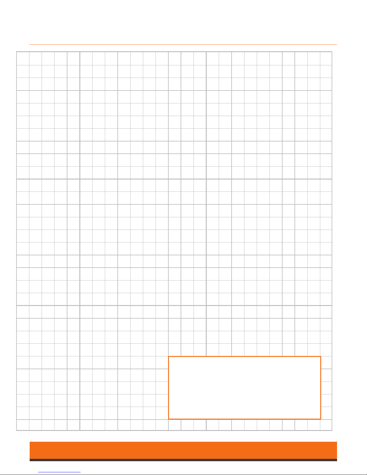
Floor Plan Sketch
Calculate your total heat area
Scale approx 1:18 (56mm = 1m)
When sketching your oor plan, please work around
any permanent / xed furniture items as these will
block the heated areas
Page 12
12
Troubleshooting
100 watt/150 watt/200 watt
Symptom Probable Causes Corrective Action
Floor does not heat No power at controller
Check power supply
RCD/MCB tripped Check the circuit is not overloaded
Thermostat not set correctly Refer to thermostat instructions
Cable not correctly connected with thermostat Refer to thermostat instructions
Floor temperature sensor not connected Refer to thermostat instructions
Faulty sensor/thermostat Contact the SmartMat Helpdesk 01473 559077
Heating element cut or damaged Contact the SmartMat Helpdesk 01473 559077
Floor warming all the time Thermostat not set correctly Refer to thermostat instructions
Floor temperature sensor not connected Refer to thermostat instructions
Floor not getting warm enough Thermostat not set correctly Refer to thermostat instructions
Floor sensor too close to heating element Contact the SmartMat Helpdesk 01473 559077
Contact the SmartMat Helpdesk with any questions on 01473 559077
Register your warranty online at:
www.smartmat.co.uk/warranty
Notes
Use this space to make notes for reference
SmartMat
Edison House
Edison Close
Ransomes Europark
Ipswich
Suolk IP3 9GU
Tel: 01473 559077
Fax: 01473 559076
Email: [email protected]
Web: www.smartmat.co.uk
Electric Underfloor Heating
 Loading...