

SmartMat Mat 100W, Mat 150W, Mat 200W Installation Manual
1
Electric Underfloor Heating
INSTALLATION MANUAL
Mat 10 0w/150w/200w
Before you begin installing, read through these instructions
carefully and check that you have all the components required.
www.smartmat.co.uk
01473 559077
LIFETIME
WARRANTY

2
Introduction
Important notes, please read carefully before proceeding with installation
The SmartMat brand
Thank you for choosing the SmartMat underoor
heating mat from our range of electric underoor
heating solutions.
The SmartMat range has been manufactured to
surpass all current industry standards and comes
with a lifetime warranty.
SmartMat underoor heating mat
The SmartMat underoor heating mat has a selfadhesive bre glass backing mesh with an ultra-thin
twin conductor 3mm heating cable pre attached,
ensuring minimal increase to the existing oor
height. The function of the matting system is to
provide a warm oor.
Superior product design ensures a speedy
installation with an even heat across the complete
oor surface, whilst allowing unlimited adjustment
of the heating element to suit irregular formats.
The SmartMat matting system is available in three
output types:
Tools needed for installation
You will require the following items to install and
test the oor warming systems.
• Tape measure, drawing pad and pencil
• Utility knife, scissors
• Cable strippers, screw driver
• Resistance tester (multimeter), insulation
resistance tester
You will also need the appropriate tools and materials
to install your nished oor surface; these will probably
include products like self-levelling compound,
insulated backer board, notched tile trowel and various
other tools and materials for your
specic project.
Dos & Don’ts
Do
Carefully read this instruction manual before starting
your installation and follow the testing procedure on
page 7. Throughout your installation:
• Take time to plan your mat layout considering all
obstacles e.g. kitchen cupboards, bathroom sinks etc.
Ensure the mat will fit before laying.
• Use flexible tile adhesives and grouting materials.
• Ensure the floor sensor thermostat is inserted within
the flexible tube provided and installed between two
heating elements, with the floor end of the flexible
tube effectively sealed (to ensure easy removal of floor
sensor if required after installation). See page 3.
• Maintain a minimum of 50mm between the heating
element runs.
• Take care not to damage the heating element and cold
tail whilst tiling.
• Ensure all the orange heating element is covered
with a flexible self-levelling compound or flexible tile
adhesive.
• Make certain there are no air gaps underneath tiled
areas or between heating element runs.
• Ensure the floor surface is prepared correctly before
installation. See note on page 4.
• When using more than one mat from a single supply,
cold tails must be connected in parallel.
Don’t
• Cut or shorten the orange heating cable.
• Cross or touch the orange heating cables together.
Switch on your under floor heating system for a
minimum of 7 days after tiling to allow correct curing
of tile adhesives and grouts.
• Connect the heating element to the power supply
whilst still rolled up.
• Leave rolled up surplus sections of mat under kitchen
units or bath spaces.
• Commence installation of your floor surface before
testing your mat. See page 7.
• Tile over damaged or twisted cables.
• Install under kitchen units or permanent fixtures such
as baths
100 watts per m
(for use with timber
oor substrates e.g.
plywood etc).
150 watts per m
(for use with concrete
oor substrates e.g. sand
cement screed, insulated
backer boards etc).
200 watts per m
(for use where a
higher wattage
output is required e.g.
conservatory).
3
Electrical Requirements
100 watt/150 watt/200 watt
Please follow these instructions carefully.
If you require assistance prior to or during
your installation please call our helpline on
01473 559077
Electrical requirements
Before installing the SmartMat you should make
allowance for the electrical connections.
The SmartMat system requires a mains voltage
230/240V and must be connected in accordance
with
the current IEE regulations and building regulations
part ‘P’ approved document.
For areas up to 30m (SmartMat 100w), areas up
to 20m (SmartMat 150w) or areas up to 15m
(SmartMat 200w) power connection can be
provided through a 13A switched spur outlet/
combined RCD spur outlet.
For areas larger than the above, a dedicated circuit
should be installed from the local consumer unit.
If you are required to switch greater electrical
load than 15A, a suitably sized thermostat or
electrical contactor MUST BE INSTALLED. If in
doubt please call our helpline on 01473 559077.
It is a requirement that all SmartMat systems are
protected by a 30ma RCD earth trip either at the
consumer unit or by a combined RCD spur outlet.
Contents of SmartMat Underoor Mat
A
E
C
D B
Important Note
When designing your electrical installation, you
should always consult an electrician regarding
your requirements.
Important Note
When installing in a bathroom or other wet areas
the thermostat must be located outside Zone 2
(0.6m from any wet appliance, e.g. shower, sink etc)
or outside the wet area, ideally on the opposite
face of the wall. The SmartMat must be earth
bonded in accordance with current IEE regulations.
• Heating mat
• Sensor tube
• Installation instructions
• Warranty
This manual contains all the
information you will
need about the
SmartMat underoor heating mat.
Please take time to study the
information thoroughly
before you
attempt to install this product.
A Heating element
B Fibreglass backing mesh
C Factory made cold tail joint
D Cold tail power lead
E End termination joint
4
Installation Instructions
100 watt/150 watt/200 watt
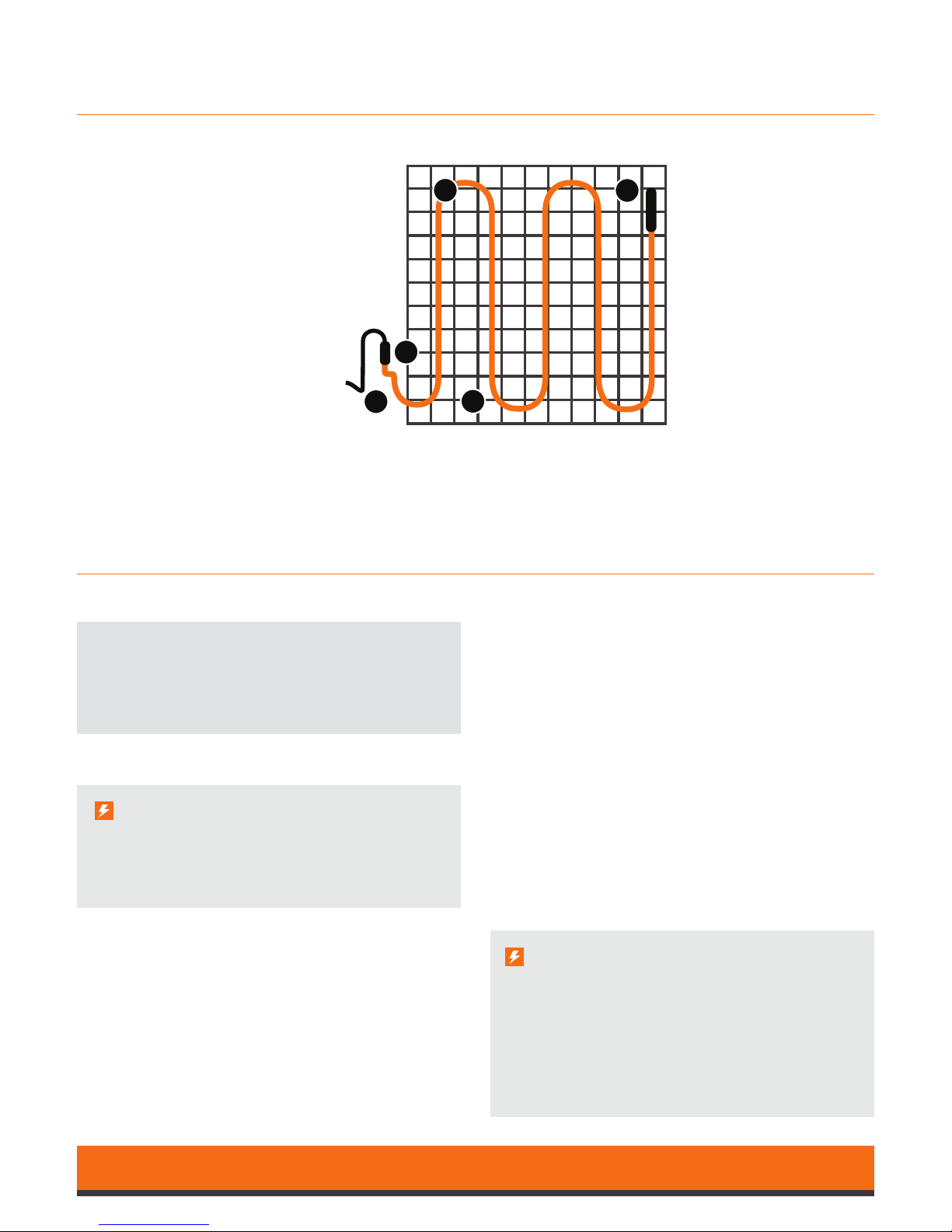
Step 1
Draw a layout of your room including all obstacles
e.g. toilet, sink etc, (use the oor plan grid on
page 10) then determine the required oor area
to be heated. Decide a suitable position for the
thermostat (start point) then sketch the proposed
SmartMat layout to ensure the heated area is
completely covered whilst using all of your mat (see
mat planner notes on page 6).
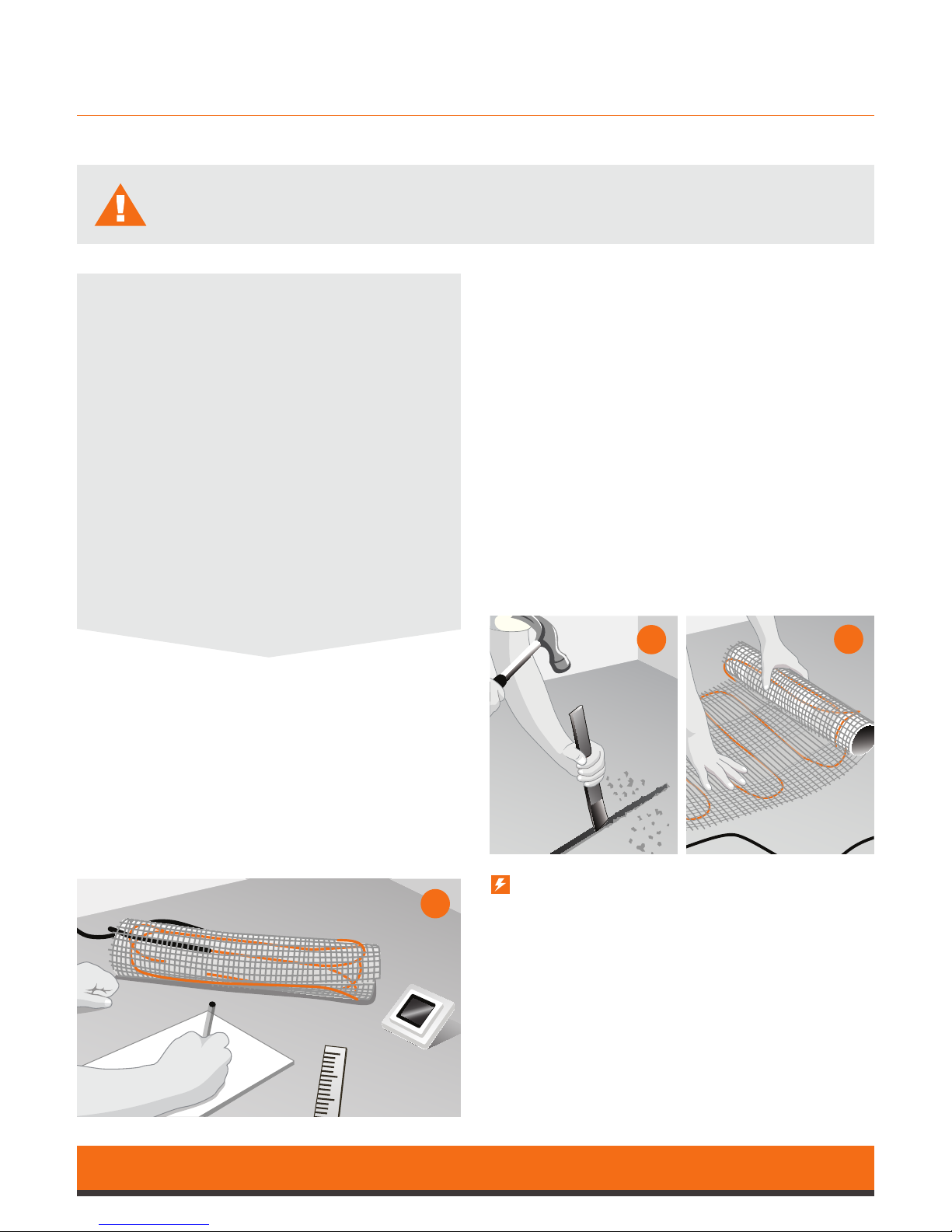
Step 2
Directly below the electrical connection point install
a 10mm exible tube (provided with each SmartMat)
–
you may have to channel a groove to allow the
exible tube to remain ush with the existing oor.
The oor sensing probe is to be installed into the
exible tube to monitor the oor temperature.
Ensure the tube is installed to allow easy replacement
of the sensor probe (in case the sensor fails) and
positioned between two heating elements.
The exible tube in the oor should be sealed to
prevent adhesive or self-levelling compound
entering the tube.
Ensure your SmartMat is correctly sized before you unpack the product.
Call 01473 559077 if you have any questions.
Note
The oor should now be prepared ready for the
SmartMat installation.
All loose particles should be removed and the
oor thoroughly cleaned and treated with any
proprietary sealants as normally required for
your nished oor.
If your existing oor has a bitumen or asphalt
surface, it must either be removed or covered
with a thin exible self-levelling compound, tile
backer board or water resistant timber.
If you are installing insulated tile backing
boards, do so in accordance with the
manufacturer’s instructions.
Now check the resistance of the mat
(see page 7 for details)
Steps 3 & 4
Remove the plastic outer cover from the SmartMat.
Position at the start of your matting plan with
the
cold tail (power cable) at the electrical connection
and positioned in to a low level electrical back box.
Ensure the separate thermostat oor sensor cable is
inserted into the pre-installed 10mm exible tube
and returned to the low level electrical back box.
1
2
3
 Loading...