


DRYER
MODELS
DEGX1 and DGGX1
517772
Fisher & Paykel Appliances © 2004 August 2004

2
SPECIFICATIONS
Operating Voltage Maximum Current
USA Electric 220/240V AC 60Hz 24 amps
USA Gas 110/120V AC 60Hz 6 amps
Igniter Gas
Cold Resistance 40 - 200 Ohms
Typical Temperature 2399°F (1315°C) @ 120V
Minimum Temperature 1805°F (985°C) @ 80V
Maximum Temperature 3092°F (1700°C) @ 132V
Valve Regulator Gas
Combination gas pressure regulator and dual automatic gas valve.
Voltage Rated 120 Volts AC 60 Hz
Resistance Across Terminals
1 & 2 1.4 kOhms
1 & 3 560 Ohms
3 & 4 1.3 kOhms
Orifice #43
Regulated pressure 3.5” H2O
Gas Flame Detector
Voltage Rated 120 Volts AC 60 Hz
Thermostat Cutout – Automatic Reset (Gas)
Type SPST
Trip Temperature 230°F ± 37° (110°C ± 3°)
Reset Temperature 203°F ± 40° (95°C ± 4.5°)
Thermostat Cutout – Manual Reset (Gas)
Type SPST
Trip Temperature 293°F (145°C)

3
Element Assembly 240 V 3.6 Kw
Two sets of Nichrome wire elements linked in parallel between Mica plates. A
ceramic insulator is used to support the element assembly in the housing.
Resistance 13.5 Ohms
Current 15 Amps
Power 3.6 KW
Voltage 240 Volts (between two phases)
Element Assembly 240V 1.4KW
Resistance 37 Ohms
Current 5.8 Amps
Power 1.4 KW
Voltage 240 Volts (between two phases)
Thermostat Cutout – Automatic Reset (Electrical)
Type SPST
Trip Temperature 158°F ± 37° (70°C ± 3°)
Reset Temperature 131°F ± 39° (55°C ± 4°)
Thermostat Cutout – Manual Reset (Electrical)
Type SPST 30 Amps/240 Volts AC
Trip Temperature 212°F (100°C)
Motor – 3 Phase 240W
Voltage Rated 190 Volts AC 85 Hz
Power 240 Watts
Current 1.6 Amps
Speed 2340 RPM
Resistance Across Any
Two Terminals of Plug 9.6 Ohms
Exhaust Temperature Sensor
Resistance (+10%) at Various Ambients
32°F (0°C) 33 kOhms
50°F (10°C) 20 kOhms
68°F (20°C) 12 kOhms
86°F (30°C) 8 kOhms
104°F (40°C) 5 kOhms
4
Lid Lock
Resistance range 63 Ohms +/- 10 Ohms @ 68°F (20°C)
Safety extra low voltage.
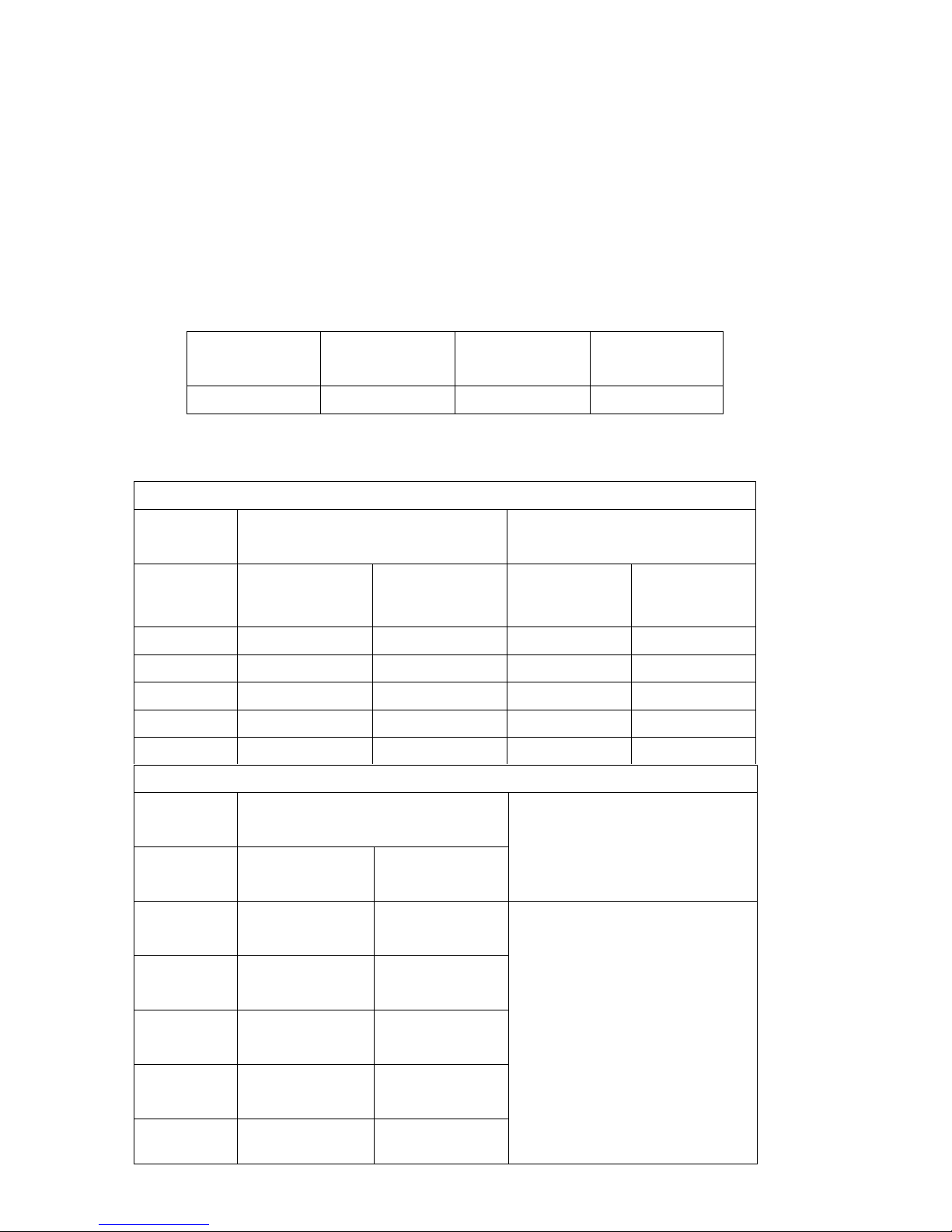
Temperatures
Each cycle, Denim through to Delicate, has a temperature limit, as defined in
the table below, as measured in the exhaust air. After switching off at the
limit, the temperature has a hysteresis of 5 degrees below these temperatures
when the heat source switches back on.
Denim Regular Permanent
Press
Delicate
149°F (65°C) 149°F (65°C) 140°F (60°C) 127°F (53°C)
When tumbling the heat source is turned on as shown in the table below:
Electric
Door Close Direction
4 minutes
Door Open Direction
40 seconds
Element 2/3
Heat
Element 1/3
Heat
Element 2/3
Heat
Element 1/3
Heat
Denim, ON ON OFF ON
Regular ON ON OFF ON
P.Press ON OFF OFF ON
Delicate ON OFF OFF ON
Air Dry OFF OFF OFF OFF
Gas
Door Close Direction
4 minutes
Door Open Direction
40 seconds
Gas Ignition
delay
Gas Heating
Denim 30 seconds 3 minutes
30 seconds
No Heat
Regular 30 seconds 2 minutes
30 seconds
P.Press 30 seconds 2 minutes
30 seconds
Delicate 30 seconds 2 minute
10 seconds
Air Dry No heat No Heat

5
DIAGNOSTICS
Overview
If a fault occurs that prevents correct operation of the dryer, and is detected
by the controllers, the dryer is stopped, the display shows a fault code and the
beeper is continuously turned on and off. Pressing the Power button will stop
the beeper but leave the fault code displayed to help the service technician
diagnose the problem. Pressing the Power button again will remove the fault
display and cause the dryer to try to start again.
If a fault occurs on a dryer, the user should be encouraged to turn the sound
off (by pressing the Power button once) but leave the displayed fault code on
for easy diagnostics.
Note: If the dryer has faulted and displayed a fault but the fault is currently not
displayed, most faults will manifest when the user attempts to run the dryer
again. However, at any time the “Last Fault” can be recalled from memory.
Diagnostic Mode
Entering the Diagnostic Mode
(a) Turn the power supply to the dryer on.
(b) Press and hold the Auto Dry down button, then press the Power
button.
The dryer is now in level 0 of the diagnostic mode. After initial entry into the
diagnostic mode, the Start/Pause button operates the dryer as normal. Press
the Auto Dry up or down buttons to scroll through the fault levels.
There are several levels of diagnostics, most of which are used in
development and production. These levels may bring on various LEDs, but
the level of use for the service technician is that of the last fault.
Last Fault
To enter the last fault diagnostics, enter the diagnostic mode as described
above, then press the Auto Dry up button three times. The last fault will be
displayed on the drying progress LEDs as described on page 7.

6
Conductivity Contact Impedance Check
To enter the conductivity contact impedance check, enter the diagnostic mode
as described above, then press the Auto Dry up button five times. In this
mode, touching damp clothes or fingers across the conductivity contacts will
cause the LED display to change. If the contacts, or the harness to them,
have gone open circuit, no change will occur in the LED display. This is a
useful method of checking the integrity of the sensor circuits.
To exit the diagnostic mode, press any cycle button.
Entering the Data Download Mode
(a) Turn the power supply to the dryer on.
(b) Press and hold the Auto Dry down button, then press the Power
button. This enters the diagnostic mode.
(c) Press the Regular button.
Encoded data is transmitted serially out the red Auto LED, and is be captured
by an optical download pen attached to a PC where “Smart Tool” software
interprets the data to aid servicing.
To exit, press the Regular button.
Entering the Showroom Mode
(a) Turn the power supply to the dryer on.
(b) Press and hold the Air Dry button, then press the Power button.
The LEDs will flash in a random sequence.
To exit, turn off the power supply to the dryer at the wall.

7
Fault Codes
The fault code is displayed in the L.E.D.s of the Drying Progress display
portion of the display panel as shown below.
Each L.E.D. illuminated represents a binary code. By adding up the binary
code value of the L.E.D.s that are illuminated, the fault code number can be
determined.
In the example above the fault code is 8+2+1 = 11
User Warnings
In the case of user warnings, the dryer may either pause, or “limp on”, and
flash an LED (see Detailed Fault Codes, page 8) at the same time as
sounding a user warning. Pressing any button will stop the sound, and
pressing the Start or Power buttons, or the completion of the cycle, will stop
the display of the warning. The warnings are stored as “faults” in memory
with their warning or fault numbers, and can be recalled as “last fault” on the
display, or by downloading the information using the Fisher & Paykel Smart
Tool diagnostic software.
Note: The blue Cool Down L.E.D. illuminated without the fault “beeps”
indicates the dryer is in a low mains voltage (brown out) state, and is
momentarily displayed whenever the supply power is turned off.

8
Detailed Fault Codes
The following are the fault codes that may be displayed. The remedy section
of each fault is the suggested sequence of repair or replacement. If the first
suggestion does not remedy the fault, check the next on the list.
Fault Code 1 Communications Error.
Communications failure between the sensor module and motor control
module.
Remedy: (1) Check the continuity of the module interconnecting harness.
(2) Replace the sensor module.
(3) Replace the motor control module.
Fault Code 2 Drum Gap Cannot be Located.
Remedy: (1) Ensure the sensor module is correctly located and clipped
into place.
(2) Replace the lens on the sensor module.
(3) Replace the sensor module.
(4) Remove the top deck and clean the drum sensing “bumps”
on the outside of the drum end.
(5) Replace the drum.

9
Fault Code 3 Drum Stalled.
Remedy: (1) If there is mechanical movement of the drum, but this fault
code is appearing, follow the procedures for fault code 2.
(2) If there is no mechanical movement of the drum, check drum
movement mechanisms: belt, motor and motor harness.
(3) Replace the motor control module.
(4) Replace the motor.
Fault Code 4 Invalid Option Link Read.
The motor control module heat source option link read is invalid.
Remedy: Replace the motor control module.
Fault Code 6 Door Jammed - User Warning.
The door is unable to close due to either clothes catching or an excessive
closing load.
Remedy: (1) Remove the obstruction.
(2) Reposition or remove some of the load.
(3) Fix the cause of binding in the door closing mechanism.
(4) Replace the motor.

10
Fault Code 7 Motor Current Excessive.
Remedy: (1) Free up the dryer. Remove overload or cause of jamming.
(2) Replace the motor control module.
(3) Replace the motor.
Fault Code 8 Exhaust Sensor Over Temperature.
The exhaust sensor measures over temperature (fire detection, element short
circuit or low resistance).
Remedy: (1) Check the integrity of the sensor circuit checking particularly
for short circuits. Approximate resistances (+10%) at various
temperatures are; 32°F (0°C) = 33 KOhms, 72°F (22°C) =
11 KOhms, 104°F (40°C) = 5 KOhms. Replace thermistor
and harness if out of range.
(2) Check the element integrity in that it switches off when the
dryer is stopped.
(3) Replace the motor control module.
(4) Replace the sensor module.
Fault Code 9 Exhaust Sensor Under Temperature.
The exhaust sensor measures under temperature (open circuit or not plugged
in).
Remedy: Refer to steps for over temperature fault (fault code 8) above, but
open circuit likely.

11
Fault Code 10 24 Volt Supply Measurement Error.
The sensor module measures low voltage on actuator power supply.
Remedy: Replace the sensor module.
Fault Code 11 Lid Lock Open Circuit.
Remedy: Check the lid lock harness and coil. If there is continuity through
these, replace the sensor module.
Fault Code 12 Lid Lock Switching Device Failure.
Remedy: Check that there are no short circuits in the lid lock circuit which
may have caused the failure in the sensor module. The
resistance of the lid lock should be between 50 and 100 ohms. If
the circuit is correct, replace the sensor module.
Fault Code 14 Sensor Module Fault.
Remedy: Replace the sensor module.

12
Fault Code 15 Sensor Module Fault.
Remedy: Replace the sensor module.
Fault Code 16 Airflow Restriction - User Warning.
Airflow restriction.
Remedy: (1) Check that the lint bucket is empty and the filter is clear.
(2) Ensure that the exhaust duct is not restricted, blocked or
kinked, preventing good airflow.
(3) Ensure that there is nothing inhibiting unrestricted airflow
through the heater housing, through the drum, lint filter, lint
collector and through the exhaust duct, and that the element
has not shorted.
(4) Check that the voltage is not too high.
(5) Check for element shorts or low resistance, or that gas
burner is operating correctly.
(6) Replace the automatic thermostat.
(7) Replace the motor control module.
Fault Code 20 Door Actuator Stalled.
Remedy: As per fault code 21.

13
Fault Code 21 Door Actuator Required Excess Voltage.
Remedy: (1) Ensure there is no weight placed on the lid of the product
(e.g. clothes basket). If so, remove the weight and retest.
(2) Inspect the installation, making sure that the cabinet sits
evenly on the floor. If excess load is placed on the cabinet, it
can cause the sub-deck assembly to twist.
(3) Inspect the front inside edge of the top deck for any signs of
excessive inwards bowing as this can cause it to catch on
the door grabber, resulting in excess current draw on
activation. The bowing can be caused by a bowed top deck
or by incorrect assembly of the top deck to the cabinet front.
(4) Ensure the user intervention tab is not inhibiting door
grabber movement.
(5) Check that the actuator linkage is located correctly. There
must be no gap between the linkage and the plastic
moulding.
(6) Check that the actuator housing is in place, and that the four
retaining lugs are correctly located. Early models may have
aluminium tape holding the housing in place. If so, ensure
that the tape is replaced when the housing is refitted.
(7) Remove the actuator housing and look for obvious signs of
things that are out of position (can the worm drive be rotated
freely both backwards and forwards by hand, is the actuator
motor in place?)
(8) Replace the faulty door actuator mechanism.
(9) Replace the door grabber, linkage and housings.
(10) Replace the sensor module.

14
Fault Code 22 Door Actuator Open Circuit.
Remedy: (1) Check that the actuator wiring is plugged into the sensor
module and is not open circuit. If faulty, replace.
(2) Replace the sensor module.
Fault Code 23 Door Actuator Movement Interrupted By Low Voltage.
The door actuator movement was interrupted by low voltage (brown out).
Remedy: (1) Ensure mains voltage is within +10% and –15% of nominal.
(2) Replace the sensor module, as voltage measurement circuit
may be reading incorrectly.
(3) Replace the motor control module, as it may not be
supplying sufficient power to the sensor module. When
display is off, approximately 24V DC is supplied.
Fault Code 24 Door Actuator Movement Took Too Long.
Remedy: As per fault code 21.

15
Fault Code 28 Data Retrieval Error Following Loss of Power
Remedy: (1) Switch off the mains power supply to the dryer for at least 10
seconds and confirm error.
(2) Replace the motor control module.
Fault Code 29 Brown-Out Data Retrieval Error.
Remedy: (1) If the fault occurs every time the dryer is turned on, replace
the sensor module.
(2) Replace the motor control module.
Fault Code 30 Lid Lock unable to Lock - User Warning.
The lid lock failed to lock. (Not user displayed.)
Remedy: (1) Ensure the lid is closed and the tongue engaged.
(2) Replace the lid lock harness.
(3) Replace the lid lock.
(4) Replace the sensor module.
Note: The blue Cool Down LED illuminated without the fault “beeps”
indicates the dryer is in a low mains voltage (brown out) state, and is
momentarily displayed whenever the supply power is turned off.
 Loading...