

SmartLine RMA801 Installation Manual
SmartLine RMA801 HART/DE Remote Indicator Assembly
Quick Start Installation Guide
34-ST-25-63, Revision 5, March 2020
This document provides descriptions
and procedures for the Quick
Installation of Honeywell’s family of
SmartLine Remote Indicator.
The SmartLine Remote Indicator is a
configurable intelligent field device
which functions as an output an d
status indicator for any HART and
DE devices.
For full details refer to the man uals
listed below for protocols , us er
Copyrights, Notices and
Trademarks.
Copyright 2020 by Honeywell
Revision 5, March 2020
Trademarks
SmartLine, RMA are U.S. registered
trademarks of Honeywell Inc.
HART® is Trademarks of
FieldComm Group™
Interface (HMI) operat ion , Ins tallation,
configuration, calib ra ti on ,
maintenance, parts, and safety and
approvals etc. including options
Documentation
To access complete documentation, including language variants, scan
the QR code below using your smart phone/device or QR code scanner.
Go to the APP store for your free Smartphone QR scanner
Or you can follow the URL to access the online SmartLine HUB page.
The HUB page will contain direct links to open SmartLine product
documentation.
URL QR Code
https://hwll.co/SmartLineHUB
Table of Contents
Installation and setup .................................................................................1
Site evaluation............................................................................................1
Installation precau tio ns ..............................................................................1
Explosion-Proof Conduit Seal ....................................................................1
Mounting Remote indicator ........................................................................2
Mounting Dimensions ................................................................................2
Bracket Mounting .......................................................................................2
Wiring a Remote Indicator .........................................................................2
Terminal Block ...........................................................................................2
Wiring Connections and Power Up ............................................................3
Wiring procedure Options ..........................................................................3
DEVICE CONFIGURATION ......................................................................3
Appendix A. PRODUCT CERTIFICATIONS .............................................3
Figure 1: Electronics Housing Components ..............................................1
Figure 2: Typical Pipe Mounted Installations .............................................2
Figure 3: Pipe Mount - Horizontal Mounting Bracket .................................2
Figure 4: Pipe Mount - Vertical Mounting Bracket .....................................2
Figure 5: Remote Indicator Secured to a Wall Mounting Bracket .............2
Figure 6: DE/ANALOG Terminal Block ......................................................2
Figure 7: RMA801 Terminal Block .............................................................2
Figure 8: Remote Indicator connected to the negative loop wire ..............3
Figure 9: Remote Indicator connected to the negative loop wire ..............3
Figure 10: Remote Indicator connected to the positive loop wire .............3
Features and Options
The RMA801 Remote Indicator provides a means of remote-mounting a indicator (display)
that is associated with a Honeywell Smartline Transmitter or any transmitter operating in a
4-20 mA current loop.
The RMA801 is a DE/Analog Remote Indicator which can be connected anywhere along
the current loop.
For analog PV, the RMA801 measures the loop current and displays the equivalent PV
value on the display.
The RMA801 will auto configure when connected to Honeywell DE transmitters except
SMV800/3000when a database upload is performed.
This document provides the information for a quick setup. For detailed information, please
refer RMA801 user manual, 34-ST-25-62.
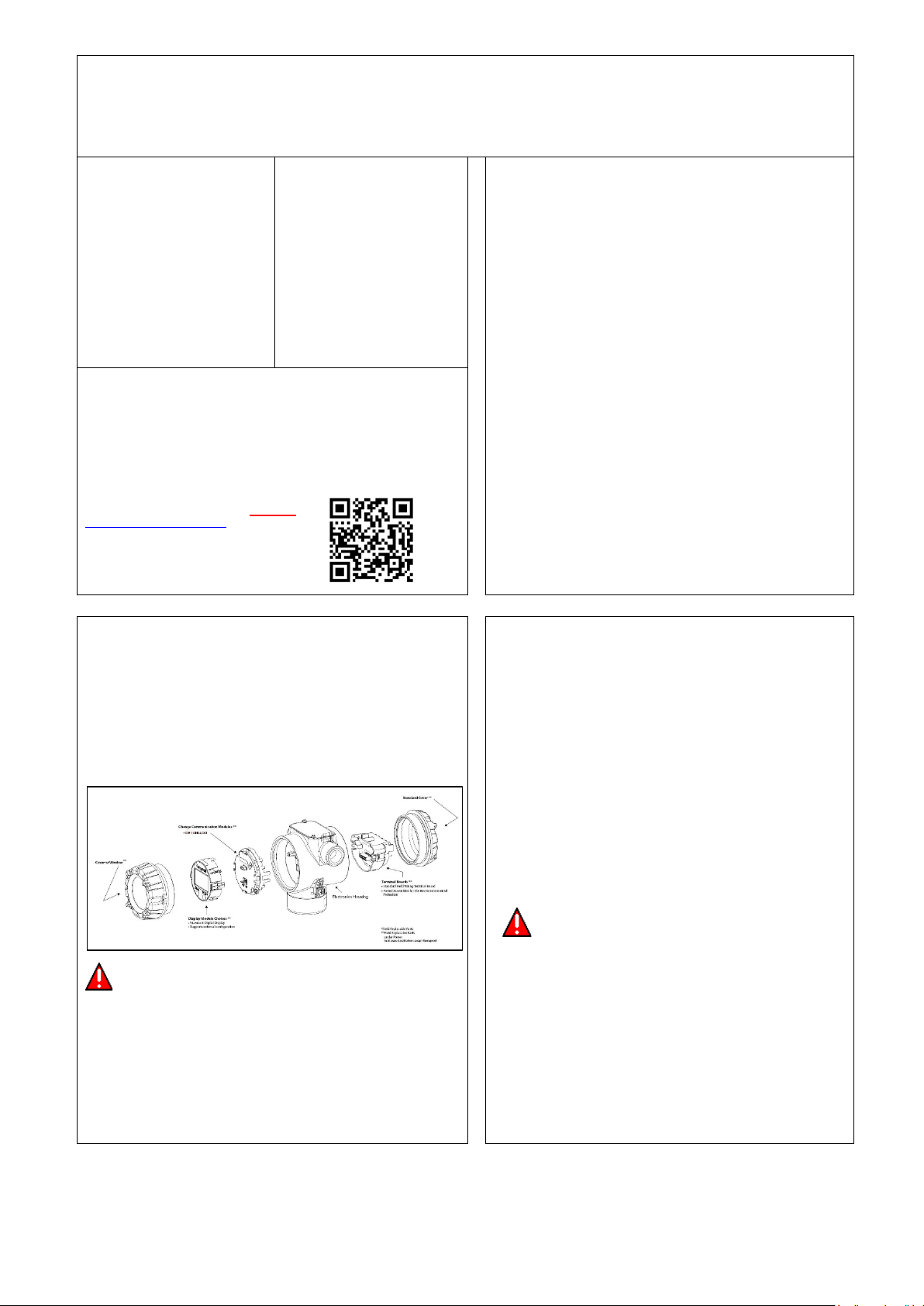
Figure 1: Electronics Housing Components
CAUTION
Temperature extremes can affect display quality. The display can go blank if the
temperature is below -20°C or above 70°C; ho wever, this is only a tem porary conditio n. The
display will again be readable when temperatures return to within operable lim its.
The device shall be operated by a t rained pr ofession al. It is the user /insta ller’s respo nsibility
to install the indicator in accordance with national and local code requirements. Conduit
entry plugs and adapters shall be suitable for the environment, shall be certified for the
hazardous location when required and accept able to the authority hav ing j urisdiction for the
plant
The RMA device is always connected in series with the transmitter. The current loop will
be broken if the RMA801 device is removed from the loop.
Installation and setup
ite evaluation
S
Evaluate the site selected for the Remote Indicator installation with respect to the
process system design specifications and Honeywell’s published performance
characteristics for your particular model. Some parameters that you may want to
include in your site evaluation can be found in the RMA801 user manual,
#34-ST-25-62
Installatio n pr ec au t i on s
Temperature extremes can affect display quality. The display can go blank if the
temperature is below -20°C or above +70°C; however, this is only a temporary
condition. The display will again be readable when temperatures return to within
operable limits.
Explosion-Proof Conduit Seal
WARNING
When installed as explosion proof in a Division 1 Hazardous Location, keep
covers tight while the Remote Indicator is energized. Disconnect power to the
Remote Indicator in the non-hazardous area prior to removing end caps for
service.
When installed as non-incendive equipment in a Division 2 hazardous location,
disconnect power to the Remote Indicator in the non-hazardous area, or
determine that the location is non-hazardous before disconnecting or
connecting the Remote Indicator wires.
Mounting Remote indicator
Terminal No.
Description
5
Loop +ve
6
Loop -ve
9
DE COMM
Summary Remote Indicator models can be attached to a two-inch (50.8 millimeter) vertical
or horizontal pipe using Honeywell’s optional pipe mounting bracket. Honeywell’s optional
wall mounting bracket is also shown in figures below.
Mounting Dimensions
Refer to Honeywell drawing number 51455045* for detailed electronic housing dimensions.
Refer to Honeywell drawing numbers 32306827* for detailed pipe mounting dimensions,
50124813* for Detailed Pipe Angle mounting dimensions and 32306828* for detailed wall
mounting dimensions.
THE TRANSMITTER ENCLOSURE CAN BE ROTATED A TOTAL OF 90° FROM THE
STANDARD MOUNTING POSITION
* Honeywell drawings can be supplied on request.
Bracket Mounting
If you are using an optional bracket, start with Step 1.
1. Pipe Mount Option -Refer to Figure 2, Figure 3 and Figure 4. Align the two
mounting holes at the bottom of the Remote Indicator with the two slots in the
mounting bracket and assemble the (2) M8 hex cap screws, (2) lock washers
and (2) flat washers provided.
2. Rotate the Remote Indicator assembly to the desired position and torque the
M8 hex cap screws to 27,0 Nm/20,0 Lb-ft maximum
3. Position the bracket on a 2-inch (50.8 mm) horizontal or vertical pipe, and
install a “U” bolt around the pipe and through the holes in the bracket. Secure
the bracket with (2) M10 hex nuts, (2) flat washers and (2) lock washers
provided. Refer to Figure 4.
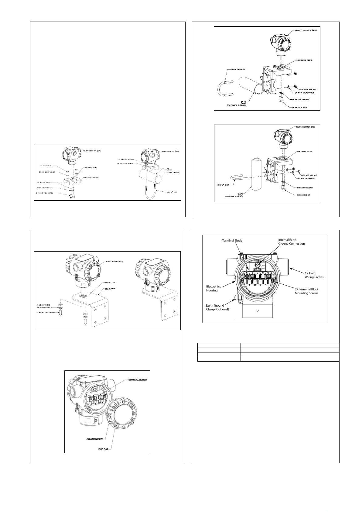
Figure 2: Typical Pipe Mounted Installations
Figure 3: Pipe Mount - Horizontal Mounting Bracket
Figure 4: Pipe Mount - Vertical Mounting Bracket
4.
Wall Mount Option – Refer Figure 5 Position the bracket on the mounting
surface at the desired location and secure the bracket to the mounting surface
using the appropriate hardware (Wall mounting hardware requirements to be
determined and supplied by the end user).
Figure 5: Remote Indicator Secured to a Wall Mounting Bracket
Wiring a Remote Indicator
Overview
The Remote Indicator is designed to operate in normal 4-20mA analog mode with HART
enabled transmitters across SmartLine Devices and DE transmitters except SMV 800/3000.
For improved noise performance, it is recommended to provide earth ground for both
transmitter and RMA housing.
Figure 6: DE/ANALOG Terminal Block
Terminal Block
The RMA801 has 3 terminals. Following table provides the connection details-
Three screw terminals suitable for wirings up to (16AWG)
• Shielded, twisted-pair cable such as Belden 9318 or equivalent must be used
for all signal/power wiring.
• The cable shield must be connected at only one end of the cable. Connect it to
the power supply side and leave the shield insulated at the transmitter side
and RMA side.
Note: If solid core wire is used strip insulation 1/4 in (6 mm). Once inserted under the
square washer the stripped portion should be contained under the square washer. If
multi-stranded wire is used, a ferrule is to be used and the stripped wire should be in
the insulated portion of the ferrule. The ferrule can be also be used on the solid core
wire.
Loop Terminals 5 & 6 shall be connected in series with the 4-20 ma loop for both
analog and DE modes. Additionally, third wire (Terminal 9) is required for DE
communication in DE mode only.
Loop wiring for analog and DE mode is shown in figure below.
After wiring the Transmitter as outline in the next sections, torque the screws to
Figure 7: RMA801 Terminal Block
NOTE:
1.1 Nm (10 lb-in)
 Loading...