

Smart Light Solutions SMART KEEPER CSK-NM10P4, SMART KEEPER CSK-NM10P8, SMART KEEPER CSK-NM10P12 User Manual
Page 1
Contact : service@smartlightsolutions.de
Smart Light Solutions GmbH, Linsenkamp 8b, 22175, Hamburg, Germany.
ㆍLocking multiple LAN cables to network ports at once.
ㆍSecure to prevent pulling the LAN cables out by unauthorized person. (4/8/12 ports)
Network Module Lock [CSK-NM10P4/8/12] User Manual
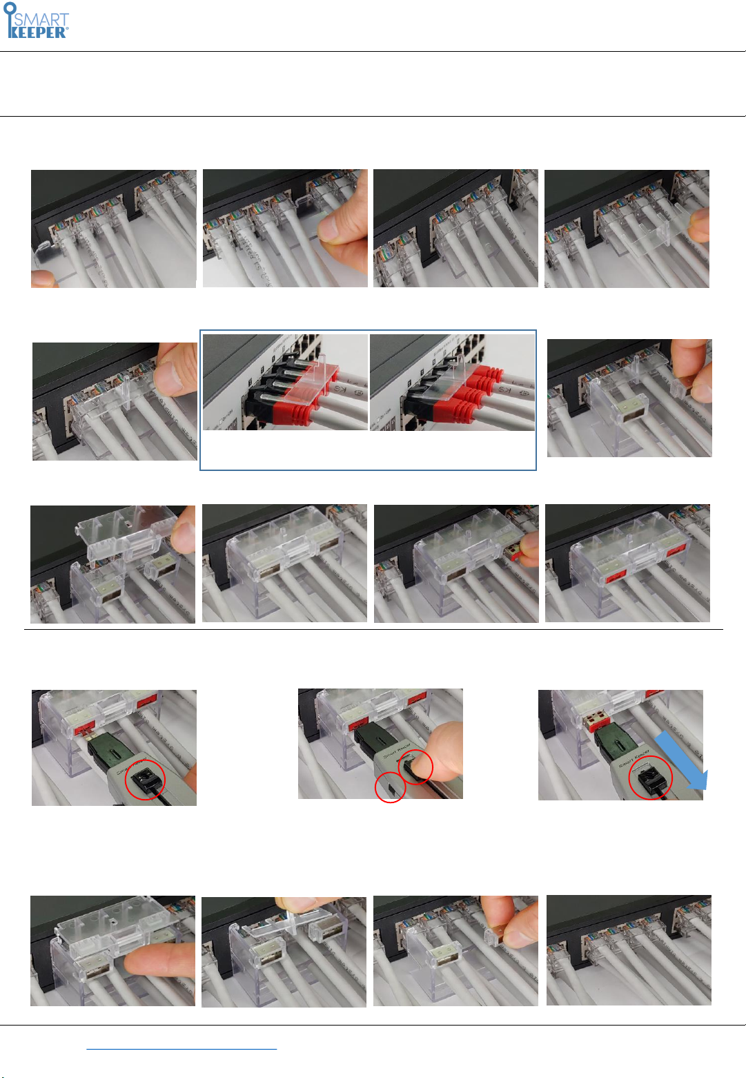
1. Installation
2. Uninstallation (For the usage of the Key - refer to the Universal Key manual)
Insert from left or right side of the cables in sequence
❶ Install Center Panel
❸ Install bottom case
❺ Insert USB Port lock
❹ Take out top cover
❻ Take out bottom case
❼ Take out center Pannel
❷ Install Guide Pin
❹ Install Top cover
Insert Guide Pin’s Bar under Locking latch
❻ Finished
❶ Insert the Key
Press “Header Open Button“
forward to change the key to
(b) Insert position
Pull the key to unplug
the USB Port Lock
Insert the key and press header
open button back to
(a) Pull out position
❷ 키 견인가능상태 변경
❸ 고정용 포트락 해제
❺ Take out Guide Bar
Page 2
Contact : service@smartlightsolutions.de
Smart Light Solutions GmbH, Linsenkamp 8b, 22175, Hamburg, Germany.
Network Module Lock [CSK-NM10P4/8/12] User Manual
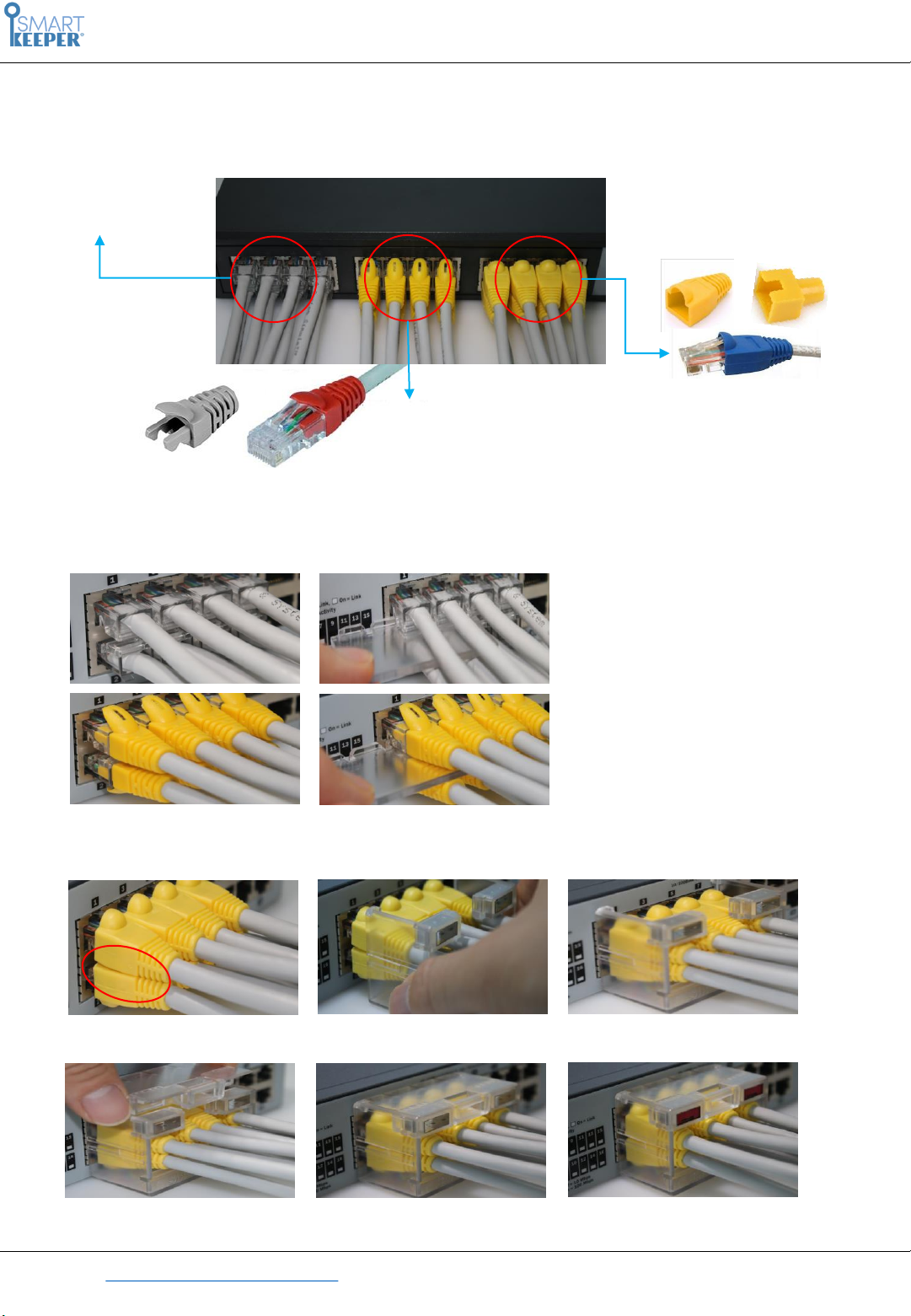
3. Installation by Boots type
This is guide for each case of boots at the back of RJ-45 connector.
(1) No Boots
Pull back or whole cover type
❶ in cases of (1)no boots or (2) Cable plug boots, installation process will be same as front page.
(You can place the center panel)
(2) Cable plug boots
❷ in case of (3) Pull back or whole cover type, there is no space for center panel. So please don’t insert the
center panel and close the top cover with bottom cover only.
There is space for center panel between
Cable on top side and bottom side
This kind of RJ-45 connect boots covers connectors give no space to place center panel.
 Loading...