

Page 1
Quick Start Guide
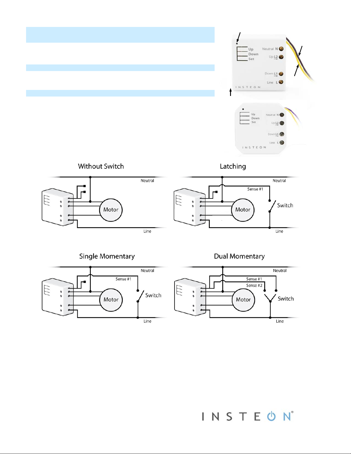
Sense #2
LED
Sense #1
Antenna
EU/AUS/NZ
North America
Down
Up
Down
Up
Down
Up
Down
Up
INSTEON® Micro Open/Close (Shutter)
Model: 2444-222/2444-422/2444-522
What’s Needed
• Slotted #1 screwdriver • Volt age meter
• Philips screwdriver • Wire cutter/str i p p e r
Installing Micro Module
Installation should only be performed by a qualified electrician or a homeowner
who is familiar and comfortable with electrical circuitry. If you have questions,
consult an electrician or call the INSTEON Support Line at 866-243-8022
1) Write down the INSTEO N ID f ound on the back of the unit (XX.XX.XX)
2) Turn off breaker/fuse and verify that the power is off
3) Disconne ct wires from existing switch, fixture or outlet and prep all wires to
be connected to Mic ro module, with 3/16” (5mm) of bare wire on the ends
4) Connect wires per diagram which corresponds to your installation
Note: sense lines carry very low current (~0.35mA 240V, ~0.17mA for 120V)
(down - purple)
(up - yellow)
5) After ensuring wires are firmly connected and that there is no exposed wire, turn on breaker/fuse
After a few seconds, Micro module LED will turn green
6) Test by tapping Micro module up/down buttons
Motor will respond accordingly
Micro Module LED will turn green when motor is moving up/open and stay green until the down button is pressed
Micro Module LED will turn red when motor is moving down/closed and stay red until the up button is pressed
7) If installing a single momentary or dual momentary switch
a) Press and hold set button until it beeps
LED will start blinking green
b) Press and hold set button until it beeps a second time
LED will start blinking red
2444-222, 2444-422, 2444-522 Rev. 9/24/2014 12: 42 P M / See Owner’s Manual for Warranty Information.
Protecte d under U.S. and fore ign patents (see www.insteon.com/patents)
© Copyright 2013 INSTEON, 16542 Millikan Ave., Ir v ine, CA 92606, 866-243-8022
Page 2

c) Press and hold set button until it beeps a third time
Micro module
Controller
LED will start blinking green
d) Perform the step that applies
• For single momentary: slowly tap set button four times
LED will continue blinking green
• For dual momentary: slowly tap set button five times
LED will start double-blinking green
• To switch back to latching: slowly tap set button six times
LED will start blinking green
e) Once the mode is selected, press and hold set button until it double-beeps
LED will stop blinking and turn green if motor is up/open or red if motor is down/closed
Calibrate Micro Module
Once wired in, you need to calibrate Micro module for the time it takes for your application—shutters, blinds, projector screens, etc.—to fully
raise/lower or open/close. Do not walk away during the calibration process as your set button taps will determine the timing. These settings can
also be configured remotely via software (sol d separat el y) .
1) Press and hold set button until it beeps
2) Press and hold set button until it beeps again
3) Press and hold set button until it beeps a third time
4) Press and hold set button until it beeps a fourth time
5) Slowly tap set button twice
6) Press and hold set button until it beeps
7) As soon as motor is fully lowered (or raised), tap set button
8) As soon as motor is fully raised (or lowered), tap set button
LED will start blinking green
LED will start blinking red
LED will start blinking green
LED will start blinking red
LED will continue blinking red
Motor will begin travelling one direction
Motor will begin travelling the opposite direction
Micro module will double-beep
Reverse Motor Direction
For some applications, such as a projector screen, you want the connected motor to lower or close your connected screen or blinds when you
press the up button or send an on command. Or you may have accidentally wired Micro module into the motor wrong. However, you don’t have to
rewire Micro module to fix it. Follow these steps to reverse the motor direction in response to commands (i.e., an on command will close/lower
while an off command will open/raise).
1) Press and hold set button until it beeps
LED will start blinking green
2) Press and hold set button until it beeps again
LED will start blinking red
3) Press and hold set button until it beeps a third time
LED will start blinking green
4) Press and hold set button until it beeps a fourth time
LED will start blinking red
5) Slowly tap set button three times
LED will continue blinking red
6) Press and hold set button until it double-beeps
7) Test by tapping connected switch up and down
Motor will now operate in the reverse direction
Make Micro Module a Responder
1) Press and hold controller set button until it beeps
Controller LED will start blinking
2) You will have four minutes to complete the next steps before linking mode times out
Adjust motor connected to Micro module to desired level
3) Press and hold Micro module set button until it double-beeps
Controller will double-beep and its LED will stop blinking
4) Test link by tapping controller button on and off or pressing and holding to brighten/dim
The motor connected to Micro module will respond appropriately
2444-222, 2444-422, 2444-522 Rev. 9/24/2014 12: 42 P M / See Owner’s Manual for Warranty Information.
Protecte d under U.S. and fore ign patents (see www.insteon.com/patents)
© Copyright 2013 INSTEON, 16542 Millikan Ave., Ir v ine, CA 92606, 866-243-8022
(Responder)
Page 3

Micro module
(Controller)
Responder
Make Micro Module a Controller
These settings can be configured remotely via software (sold separately). You can also add Micro module to your network
manually by following the instructions below. Note: you must perform these steps before reinstalling the wall switch.
1) Press and hold Micro module set button until it beeps
Micro module LED will start blinking green
2) You will have four minutes to complete the next steps before linking mode times out
Adjust responder to desired state
3) Press and hold responder set button until it double-beeps
Micro module will double-beep and its LED will stop blinking
4) Test link by tapping switch connected to Micro module to turn up/down
Responder will respond appropriately
Assign an X10 Address
1) Press and hold Mic ro module set button until it beeps
Micro module LED will start blinking green
2) Send the X10 address 3 times (with or without commands)
Example: A1-A1-A1-AON or A1-AON-A1-AON-A1-AON
Micro module will double-beep and its LED will stop blinking
3) Test by sending X10 on and off commands
The motor connected to Micro module will respond appropriately
Owner’s Manual and Tech Support
Visit: http://www.insteon.com/support for complete manual, online tech support and latest product documents.
Call: INSTEON Support Line at 866-243-8022
FCC Compliance
This device complies with Part 15 of the FCC Rules and Industry Canada licence-exempt RSS standard(s). Operation is subject to the following two conditions: (1) this device may not cause interference, and (2) this device must accept
any interference, including interference that may cause undesired operation of the device.
Le présent appareil est conforme à l’article 15C des règlements de la FCC et CNR d'Industrie Canada applicables aux appareils radio exempts de licence. L'exploitation est autorisée aux deux conditions suivantes : (1) l'appareil ne doit
pas produire de brouillage, et (2) l'utilisateur de l'appareil doit accepter tout brouillage radioélectrique subi, même si le brouillage est susceptible d'en compromettre le fonctionnement.
2444-222, 2444-422, 2444-522 Rev. 9/24/2014 12: 42 P M / See Owner’s Manual for Warranty Information.
Protecte d under U.S. and fore ign patents (see www.insteon.com/patents)
© Copyright 2013 INSTEON, 16542 Millikan Ave., Ir v ine, CA 92606, 866-243-8022
 Loading...