

Quick Start Guide
®
INSTEON
Micro Relay
Model: 2443-222/2443-422/2443-522
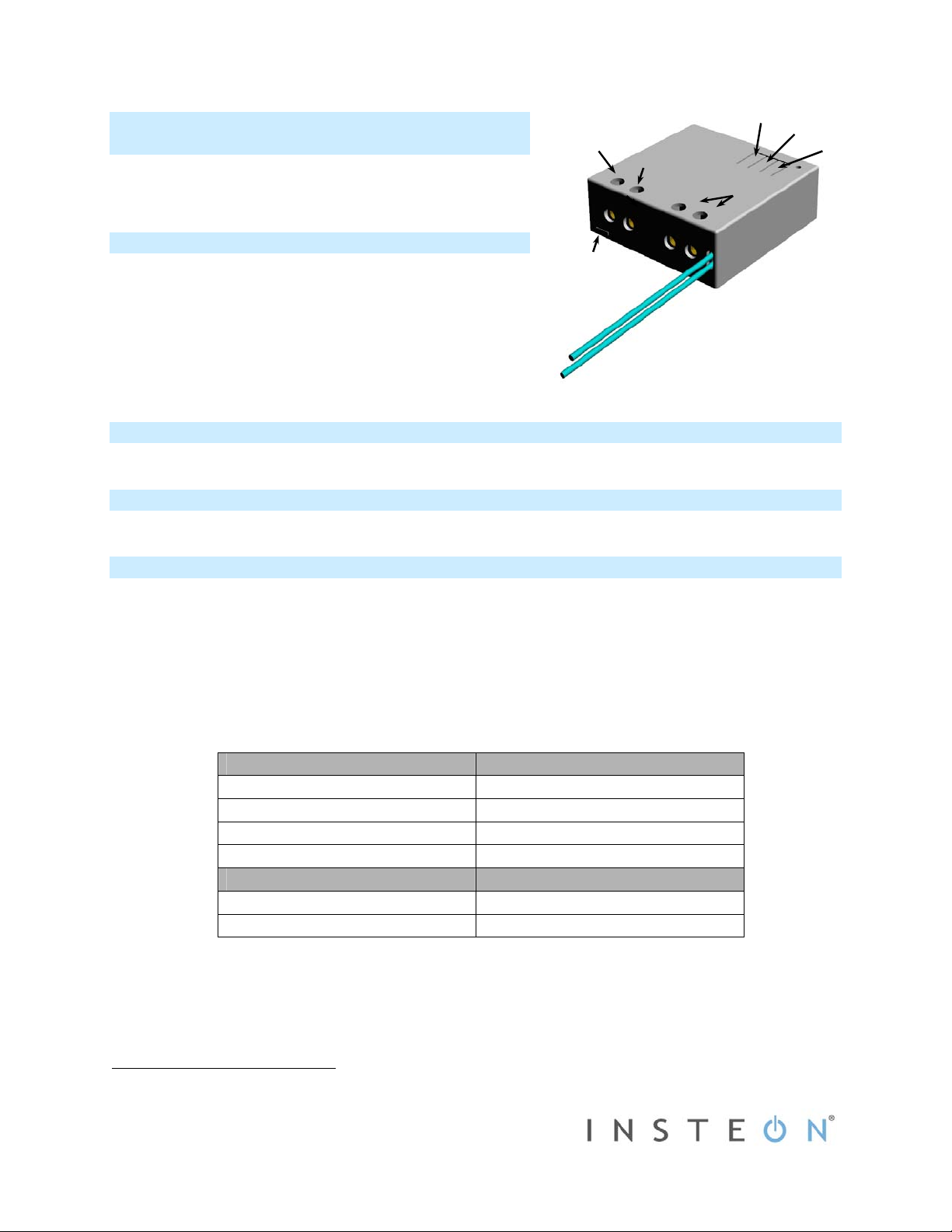
Terminal #1
(Line)
Terminal #2
(Load)
Set button
Off button
On button
Terminals #3 and
#4 (Neutral)
About INSTEON Micro Relay
Congratulations on your purchase of the INSTEON® Micro Relay!
This compact on/off relay module wires in behind an existing wall
switch to give you complete—and completely hidden—remote
control over compatible lights.
Installation should only be performed by a qualified
Note:
electrician or a homeowner who is familiar and comfortable with
electrical circuitry. If you have questions, consult an electrician or
call the INSTEON Support Line at 800-762-7845.
Set button
In the Box
- INSTEON Micro Relay
What’s Needed
- Flathead screwdriver - Philips screwdriver - Wire cutter/stripper - Voltage meter
Installing INSTEON Micro Relay (Dual Momentary Switch)
1) Before installing, write down Micro Relay’s INSTEON I.D. (on sticker) for future reference.
2) Turn off breaker/fuse
3) Remove wallplate and unscrew existing switch.
4) Gently pull switch out of wall and disconnect wires.
5) After ensuring that the wires are not touching, turn breaker back on.
6) Use a voltage meter to identify the fixture’s Line, Load and Neutral wires.
7) Turn off breaker again.
8) Connect Micro Relay wires as follows:
9) Turn breaker back on.
Connected load will turn on and Micro Relay’s LED will turn on green.
10) Test connection by tapping Micro Relay’s on/off buttons.
Connected load will turn on and off and Micro Relay’s LED will turn green (on) and red (off).
1
and verify that the power is off.
2
Micro Relay House
Terminal #1 Line (100-277VAC)
Terminal #2 Load (light, fan, etc.)
Terminal #3 Neutral
Terminal #4 Neutral
Micro Relay Switch
Yellow wire Momentary on
Purple wire Momentary off
1
If multi-gang box, turn off all breakers/fuses that may be supplying power to the box.
2
If the wires cannot be detached, cut wires where they enter the switch and strip ½” of insulation off the ends.
2443-222 Rev. 5/17/2012 1:55 PM / See Owner’s Manual for Warranty Information.
Protected under U.S. and foreign patents (see www.insteon.com)
© Copyright 2012 INSTEON, 16542 Millikan Ave., Irvine, CA 92606, 800-762-7845
11) If you are planning to manually link Micro Relay to any INSTEON controllers, do so now (see
as an INSTEON Responder
below).
12) Turn breaker off.
13) Place Micro Relay in rear of wall box.
14) Remount switch in wall box.
15) Turn breaker back on.
Connected load will turn on at its previous state (prior to turning off breaker).
16) Test installation by tapping switch on and off.
Connected load will turn on and off.
17) Reinstall wallplate.
Installing INSTEON Micro Relay (Single Momentary Switch)
1) Before installing, write down Micro Relay’s INSTEON I.D. (on sticker) for future reference.
2) Turn off breaker/fuse1 and verify that the power is off.
3) Remove wallplate and unscrew existing switch.
4) Gently pull switch out of wall and disconnect wires.2
5) After ensuring that the wires are not touching, turn breaker back on.
6) Use a voltage meter to identify the fixture’s Line, Load and Neutral wires.
7) Turn off breaker again.
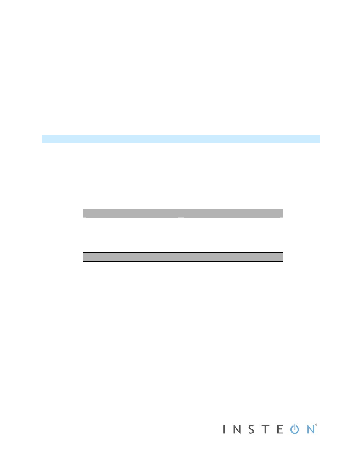
8) Connect Micro Relay wires as follows:
Micro Relay House
Terminal #1 Line (100-277VAC)
Terminal #2 Load (light, fan, etc.)
Terminal #3 Neutral
Terminal #4 Neutral
Micro Relay Switch
Yellow wire Switch contact
Purple wire Not used – cap off
9) Turn breaker back on.
Connected load will turn on and Micro Relay’s LED will turn on green.
10) Test connection by tapping Micro Relay’s on/off buttons.
Connected load will turn on and off and Micro Relay’s LED will turn green (on) and red (off).
11) If you are planning to manually link Micro Relay to any INSTEON controllers, do so now (see
as an INSTEON Responder
below).
12) Turn breaker off.
13) Place Micro Relay in rear of wall box.
14) Remount switch in wall box.
15) Turn breaker back on.
Connected load will turn on at its previous state (prior to turning off breaker).
16) Test installation by tapping switch on and off.
Connected load will turn on and off.
17) Reinstall wallplate.
1
If multi-gang box, turn off all breakers/fuses that may be supplying power to the box.
2
If the wires cannot be detached, cut wires where they enter the switch and strip ½” of insulation off the ends.
2443-222 Rev. 5/17/2012 1:55 PM / See Owner’s Manual for Warranty Information.
Protected under U.S. and foreign patents (see www.insteon.com)
© Copyright 2012 INSTEON, 16542 Millikan Ave., Irvine, CA 92606, 800-762-7845
Adding Micro Relay
Adding Micro Relay
 Loading...