

Page 1
Quick Start Guide
®
INSTEON
DIN Rail On/Off
Model: 2452-222/2452-422/2452-522
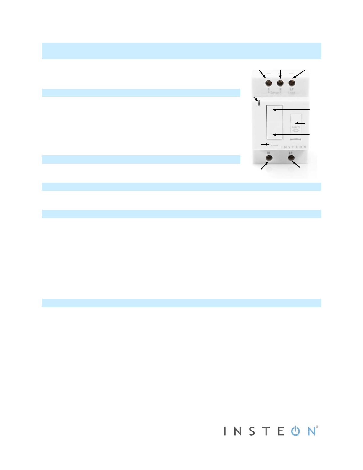
Sense #1
Sense #2
Connected
load
About INSTEON DIN Rail On/Off
The compact INSTEON DIN Rail On/Off module installs directly onto the DIN rail to
give you remote control over compatible lights and applianc es.
Installation should only be performed by a qualified electrician or a
Note:
homeowner who is familiar and comfortable with electrical circuitry. If you have
questions, consult an electrician or call the INSTEON Support Line at 800-762-
7845.
LED
Paddle top
(on)
Fuse
Paddle bottom
Set
button
In the Box
- INSTEON DIN Rail On/Off
Line
Neutral
What’s Needed
- Flathead screwdriver - Wire cutter/stripper - Voltage meter
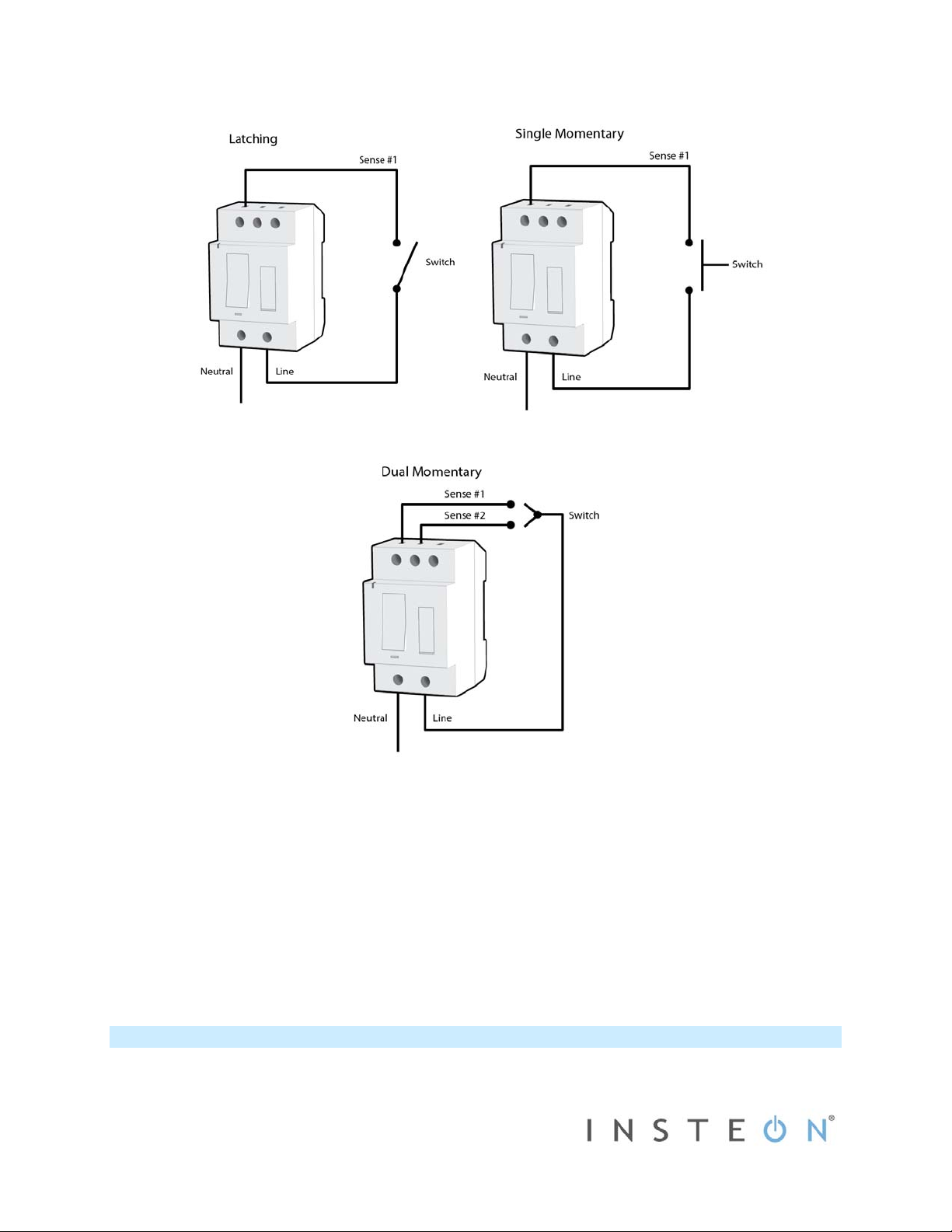
Before Installation
Before you install DIN Rail Module behind a switch, you must determine which switch operation mode applies to your
switch—latching, single momentary or dual momentary—as each is wired differently:
Latching (default mode): Switch has no central position. It can be tapped on both the top and bottom and
remains in that state once released.
Single momentary: Switch can only be tapped in one location. It returns to central position once released.
Dual momentary: Switch can be tapped on both the top and bottom. It returns to central position once
released.
Once you have identified your switch type, install DIN Rail Module according to the corresponding wiring diagram,
then see “Switch Operation Mode” to program DIN Rail Module for your specific switch type.
(off)
Install INSTEON DIN Rail On/Off
1) Turn off breaker/fuse and verify that the power is off
2) At the DIN rail, strip away wire coating until you have 10mm (1/3”) of bare wire on the ends.
3) After ensuring the wires are not touching, turn on breaker/fuse
4) Use a voltage meter to identify the fixture’s line, load and neutral wires, then turn off breaker/fuse again
5) For reference, write down the INSTEON I.D. (on the side of the module) and the load it is controlling
6) Snap module onto DIN rail. (If installing next to another module, allow 2cm between modules for heat
dissipation.)
7) Connect line, load, neutral and sense wires according to the diagram corresponding to your switch type:
2453-222/2453-422/2453-522 Rev. 8/13/2012 9:25 AM / See Owner’s Manual for Warranty Information.
Protected under U.S. and foreign patents (see www.insteon.com)
© Copyright 2012 INSTEON, 16542 Millikan Ave., Irvine, CA 92606, 800-762-7845
Page 2
8) After ensuring wires are firmly connected and that there is no exposed wire, turn on breaker/fuse
Load will turn on and DIN Rail module LED will turn on green
9)
Test connection by tapping DIN Rail module paddle top and bottom
Load will turn on and off
10) If you are installing a single momentary or dual momentary switch, follow the instructions in
below to program the correct mode for your switch
Mode
11) If you are planning to manually link DIN Rail module to any INSTEON devices, do so no w (see
Module a Responder
and
Make DIN Rail Module a Controller
Switch Operation
Make DIN Rail
below)
12) Test installation by tapping switch connected to DIN Rail module on and off
Load will turn on and off
Switch Operation Mode
By default, DIN Rail module is programmed for a latching switch. Program the switch operation for single momentary
mode, dual momentary mode or back to latching mode according to your switch type.
2453-222/2453-422/2453-522 Rev. 8/13/2012 9:25 AM / See Owner’s Manual for Warranty Information.
Protected under U.S. and foreign patents (see www.insteon.com)
© Copyright 2012 INSTEON, 16542 Millikan Ave., Irvine, CA 92606, 800-762-7845
Page 3

To determine DIN Rail module’s current switch operation mode, simply tap Set button:
If it beeps, DIN Rail module is configured for a single momentary switch
If it double-beeps, DIN Rail module is configured for a dual momentary switch
If it triple-beeps, DIN Rail module is configured for a latching switch (default)
Change to Single Momentary Mode
1) Press and hold Set button until it beeps
LED will start blinking green
2) Press and hold Set button until it beeps again
LED will start blinking red
3) Press and hold Set button until it beeps a third time
LED will start blinking green
4) Slowly tap Set button four times
LED will continue blinking green
5) Press and hold Set button until it double-beeps
LED will stop blinking
6) Test mode change by tapping switch on and off
Load will respond appropriately
Change to Dual Momentary Mode
1) Press and hold Set button until it beeps
LED will start blinking green
2) Press and hold Set button until it beeps again
LED will start blinking red
3) Press and hold Set button until it beeps a third time
LED will start blinking green
4) Slowly tap Set button five times
LED will start double-blinking green
5) Press and hold Set button until it double-beeps
LED will stop blinking
6) Test mode change by tapping switch top and bottom
Load will respond appropriately
Change to Latching Mode (default)
1) Press and hold Set button until it beeps
LED will start blinking green
2) Press and hold Set button until it beeps again
LED will start blinking red
3) Press and hold Set button until it beeps a third time
LED will start blinking green
4) Slowly tap Set button six times
LED will continue blinking green
5) Press and hold Set button until it double-beeps
LED will stop blinking
6) Test mode change by tapping switch on and off
Load will respond appropriately
Make DIN Rail On/Off a Responder
1) Press and hold controller Set button until it beeps
Controller LED will start blinking green
2) Adjust load connected to DIN Rail module to desired level
3) Press and hold DIN Rail module Set button until it double-beeps
Controller will double-beep and its LED will stop blinking
2453-222/2453-422/2453-522 Rev. 8/13/2012 9:25 AM / See Owner’s Manual for Warranty Information.
Protected under U.S. and foreign patents (see www.insteon.com)
© Copyright 2012 INSTEON, 16542 Millikan Ave., Irvine, CA 92606, 800-762-7845
Page 4

4) Test by tapping controller button on and off
Load connected to DIN Rail module will turn on and off
Make DIN Rail On/Off a Controller
1) Press and hold DIN Rail module Set button until it beeps
DIN Rail module LED will start blinking green
2) Adjust responder to desired brightness state (such as on, 50% or even off)
3) Press and hold responder Set button until it double-beeps
DIN Rail module LED will stop blinking
4) Test by tapping DIN Rail module paddle top and bottom to turn on/off or brighten/dim
Responder will respond appropriately
Owner’s Manual and Tech Support
Owner’s Manual and Quick Start Guide: http://www.insteon.com/support
Call: INSTEON Support Line at 800-762-7845
FCC Compliance
This device complies with FCC Rules Part 15. Operation is subject to two conditions:
(1) This device may not cause harmful interference, and
(2) This device must accept any interference that may be received or that may cause undesired operation.
The digital circuitry of this device has been tested and found to comply with the limits for a Class B digital device, pursuant to Part 15 of the FCC Rules.
These limits are designed to provide reasonable protection against harmful interference in residential installations. This equipment generates, uses and
can radiate radio frequency energy and, if not installed and used in accordance with the instructions, may cause harmful interference to radio and
television reception. However, there is no guarantee that interference will not occur in a particular installation. If
this device does cause such interference, which can be verified by turning the device off and on, the user is encouraged to eliminate the interference
by one or more of the following measures:
WARNING! Changes or modifications to this device not expressly approved by the party responsible for compliance could void the user's authority to
operate the equipment.
• Re-orient or re-locate the receiving antenna of the dev ice experiencing the interference.
• Increase the distance between this device and the receiver.
• Connect the device to an AC outlet on a circuit different from the one that supplies power to the receiver.
• Consult the dealer or an experienced radio/TV technician.
IC Compliance
This device complies with Industry Canada licence-exempt RSS standard(s). Operation is subject to the following two conditions: (1) this device may
not cause interference, and (2) this device must accept any interference, including interference that may cause undesired operation of the device.
Le présent appareil est conforme aux CNR d'Industrie Canada applicables aux appareils radio exempts de licence. L'exploitation est autorisée aux
deux conditions suivantes : (1) l'appareil ne doit pas produire de brouillage, et (2) l'utilisateur de l'appareil doit accepter tout brouillage radioélectrique
subi, même si le brouillage est susceptible d'en compromettre le fonctionnement.
2453-222/2453-422/2453-522 Rev. 8/13/2012 9:25 AM / See Owner’s Manual for Warranty Information.
Protected under U.S. and foreign patents (see www.insteon.com)
© Copyright 2012 INSTEON, 16542 Millikan Ave., Irvine, CA 92606, 800-762-7845
 Loading...