

Page 1
Quick-Start Guide
y
7 Day Thermostat
Model: 4715
Installation
1) RF-only devices require at least one dual-band INSTEON product for communication. For the best INSTEON
network performance, be sure you have properly installed at least two dual-band INSTEON products.
2) Remove the old thermostat, but keep the old thermostat for reference purposes, until 7 Day Thermostat is
functioning properly
3) Remove the front cover from 7 Day Thermostat
4) Mount 7 Day Thermostat using the included hardware
5) Configure the jumpers. (See the 7 Day Thermostat Installation and Programming Guide.)
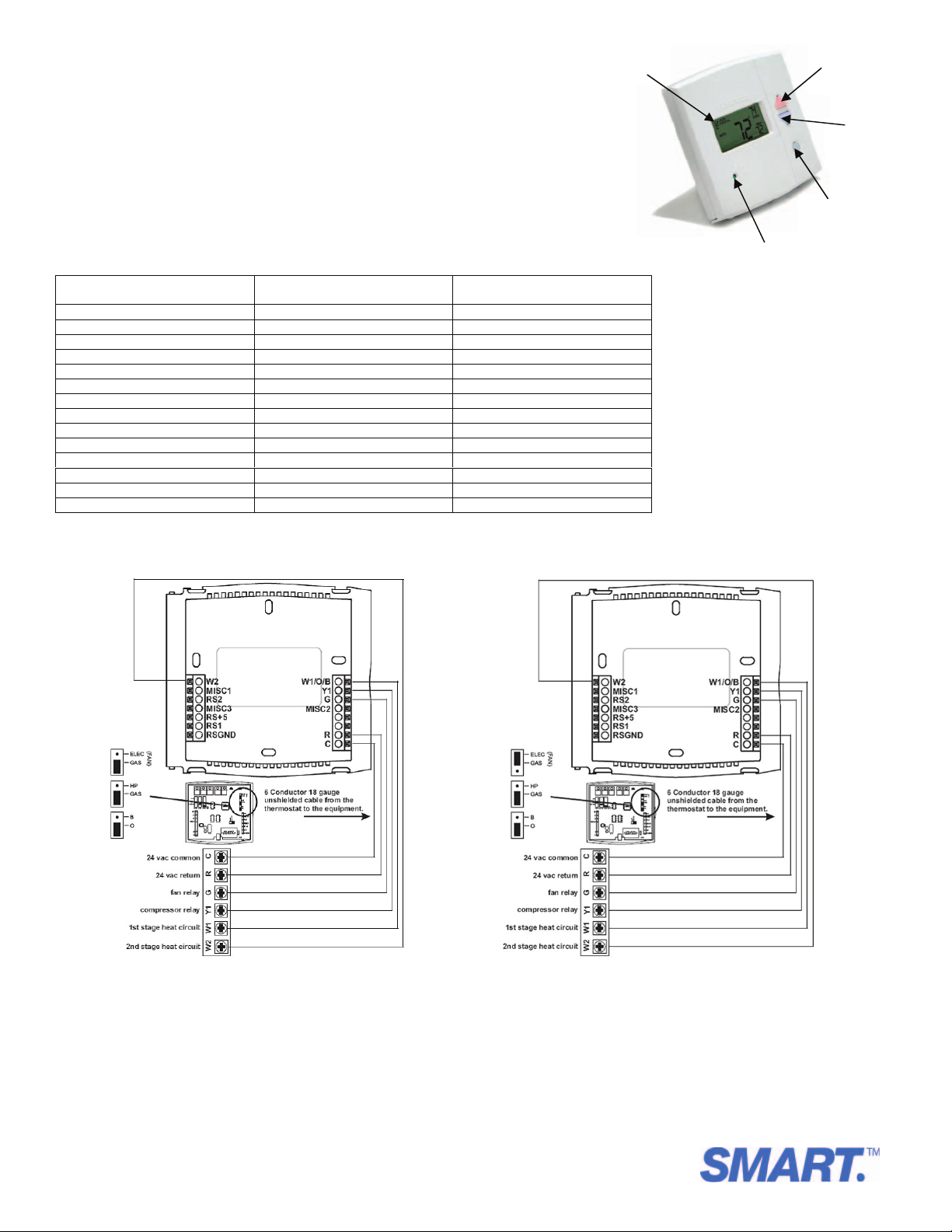
6) Refer to the chart and diagrams below for basic 1 stage cooling, 1 stage heat wiring. For other wiring
diagrams, see the Installation and Programming Guide.
Wire from the old thermostat
terminal marked
G or F Fan G
Y1, Y, or C Cooling Y1
W1, W or H Heating W1/O/B
Rh, R, M, Vr, A Power R
C Common C
O/B Rev. Valve W1/O/B
W2 2nd Stage Heat W2
MISC1 Configurable Output #1 MISC1
MISC2 Configurable Output #2 MISC2
MISC3 Configurable Output #3 MISC3
RS+5 Remote Sensor +5vdc RS+5
RS1 Remote Sensor Signal RS1
RSGND Remote Sensor Ground RSGND
RS2 Remote Sensor Signal #2 RS2
7) Reattach the front cover to 7 Day Thermostat
Wiring Diagrams
Residential & Commercial 1 Stage Cooling, with 1st Stage Gas Heat Residential & Commercial 1 Stage Cooling, with 1st Stage Electric Heat
Function
Install on the new thermostat
connector marked
Backlit LCD
Display
Mode button
Heat or Cool
Demand Indicator
Controlling 7 Day Thermostat
• Tap an On or Scene button on a Linked Controller to recall the thermostat mode and set points established during Linking
• Tap an Off button on a Linked Controller to turn off the thermostat and set points established during Linking
• Tap the Bright* button on a Linked Controller to raise the set point(s) by a single degree
• Tap the Dim* button on a Linked Controller to lower the set point(s) by a single degree
*To prevent “runawa
” temperature set points, these operations only apply to Controllers with Bright/Dim buttons.
Up button
(glows red)
Down button
(glows blue)
Page 1 of 2
Rev. 09-23-2010
SMART Limited Warranty – SMART warrants to original consum er of this product for a period of 2 years from date of purchase, this produc t will be free from
defects in material & workmans hip & will perform in substantial c onformity with its Owner's Manual. W arranty shall not apply to def ects caused by misuse or
neglect.
U.S. Patent No. 7,345,998, International patents pending © Copyright 201 0
SMART, 16542 Millikan Ave., Irvine, C A 92606, 866-883-9220
Page 2
FCC & Industry Canada Compliance Statement
This device complies with FCC Rules Part 15 and Industry Canada RSS-210 (Rev. 7). Operation is subject to the following two conditions:
(1) This device may not cause harmful interference, and
(2) This device must accept any interference, including interference that may cause undesired operation of the device.
The digital circuitry of this device has been tested and found to comply with the limits for a Class B digital device, pursuant to Part 15 of the FCC Rules. These
limits are designed to provide reasonable protection against harmful interference in residential installations. This equipment generates, uses, and can
radiate radio frequency energy and, if not installed and used in accordance with the instructions, may cause harmful interference to radio and television
reception. However, there is not guarantee that interference will no occur in a particular installation. If this device does cause such interference, which can
be verified by turning the device off and on, the user is encouraged to eliminate the interference by one or more of the following measures:
• Re-orient or relocate the receiving antenna of the device experiencing the interference
• Increase the distance between this device and the receiver
• Connect the device to an AC outlet on a circuit different from the one that supplies power to the receiver
• Consult the dealer or an experienced radio/TV technician
WARNING! Changes or modifications to this unit not expressly approved by the party responsible for compliance could void the user’s authority to operate
the equipment.
Complete Instructions, Troubleshooting, and Tech Support
Call: Tech. Support @ 866-883-9220
Contact Us Online:
www.smartproline.com
Page 2 of 2
Rev. 09-23-2010
SMART Limited Warranty – SMART warrants to original consum er of this product for a period of 2 years from date of purchase, this produc t will be free from
defects in material & workmans hip & will perform in substantial c onformity with its Owner's Manual. W arranty shall not apply to def ects caused by misuse or
neglect.
U.S. Patent No. 7,345,998, International patents pending © Copyright 201 0
SMART, 16542 Millikan Ave., Irvine, C A 92606, 866-883-9220
 Loading...