

Page 1
Quick-Start Guide
LampLinc™ Dual-Band – INSTEON® Dual-Band
Plug-In Lamp Dimmer Module, 2-Pin
Model: 2457D2 – Dim and remotely control any lamp in your home at the
touch of a button. Can also be used to bridge the phases in your home
(just like an INSTEON Access Point module).
Installation
1) Plug the lamp you want to control into the outlet on LampLinc Dual-Band
2) Plug LampLinc Dual-Band into an unswitched wall outlet
3) The lamp you plugged in should turn on. If the lamp does not turn on,
The LED will be solid green
If the LED is solid red, tap the Up button. The LED will turn to solid
green.
turn it on manually using the switch on the lamp itself.
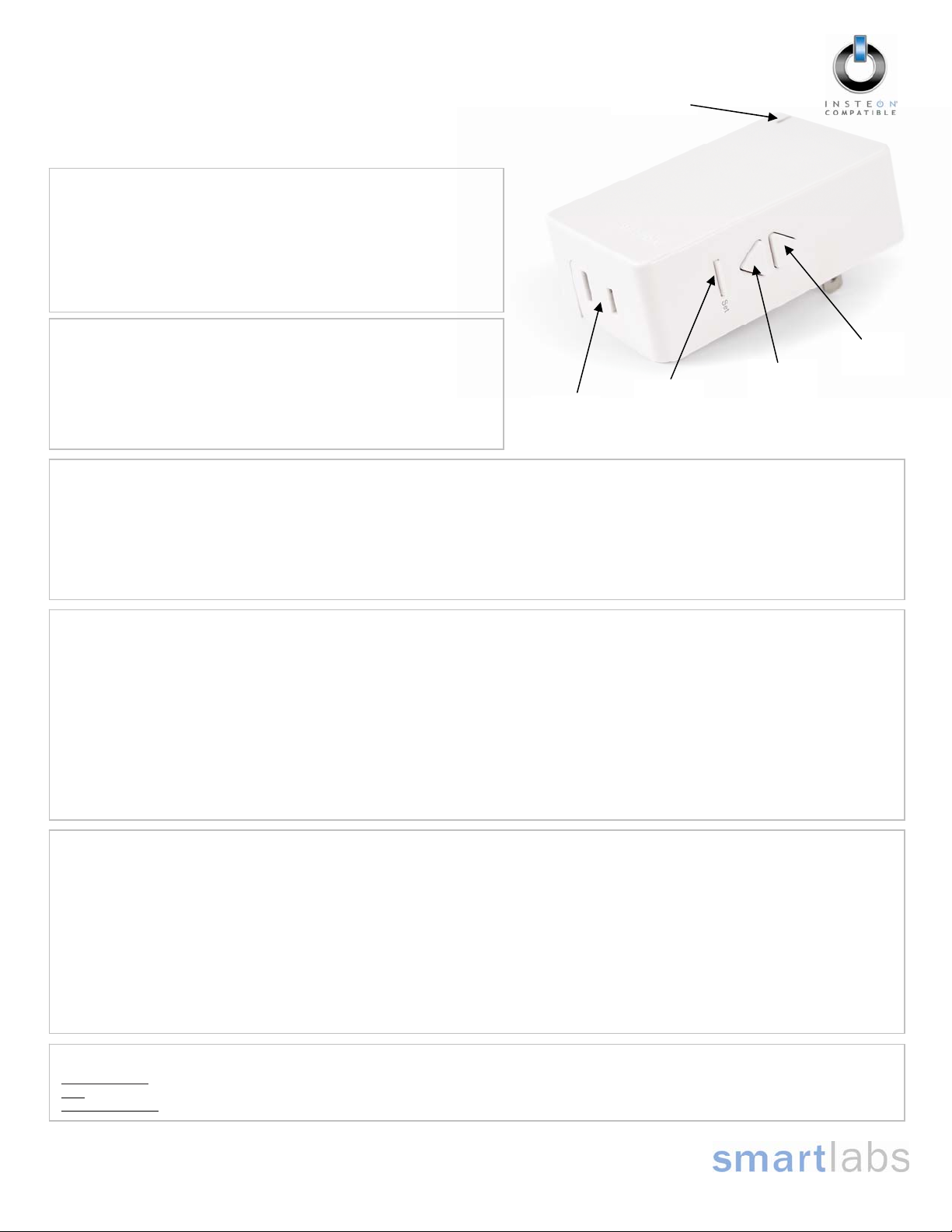
Status LED
Using the LampLinc Dual-Band Buttons
• Tap the Up button to turn your light on
• Tap the Down button to turn your light off
• Press & hold the Up button to brighten your light
• Press & hold the Down button to dim your light
• Double-tap the Up button to turn your light on at 100% instantly
• Double-tap the Down button to turn your light off instantly
Outlet
Set
button
Down
button
Up
button
Linking LampLinc Dual-Band to an INSTEON Controller
1) Set your INSTEON Controller to Linking Mode. (For most Controllers, you just press an On or Scene button for 10 seconds, or the Set button for 3
seconds). Refer to your Controller’s Owner’s Manual for more detailed instructions.
2) From LampLinc Dual-Band, use the Up and/or Down buttons to adjust the light to the desired brightness level. (Pressing & holding the Up button
will brighten the light, while pressing & holding the Down button will dim it).
3) Press & hold the LampLinc Dual-Band Set button until it double-beeps (about 3 seconds)
4) Test that Linking was successful by pressing the buttons on the Controller you just Linked to the LampLinc Dual-Band
The controlled light will flash
Using LampLinc Dual-Band to Bridge Phases
LampLinc Dual-Band can help bridge the phases in your home like an Access Point. Use the following procedure to test that the phases have been
bridged.
1) Start Phase Bridging Detection Mode by tapping the LampLinc Dual-Band Set button 4 times quickly
2) Now, check the LED behavior of your other dual-band devices. Verify at least 1 of your dual-band device LEDs does one of the following:
3) If none of your dual-band devices exhibit the behavior in Step 2, try:
4) Tap the LampLinc Dual-Band Set button to exit Phase Bridging Detection Mode
LampLinc Dual-Band will begin beeping continuously once per second and the LED will be solid green
• If your other dual-band devices are Rev 2.0 or above, the Status LED will blink green
• If your other dual-band devices are below Rev 2.0, the Status LED will be bright, solid white or blue
• Following steps 1 and 2 with your other dual-band devices to see if they are bridging the phases
• Moving your other dual-band devices to other locations until they exhibit the desired LED behavior
LampLinc Dual-Band will stop beeping
FCC Compliance Statement
This device complies with FCC Rules Part 15.Operation is subjec t to 2 conditions:
(1) This device may not cause harmful interference, and
(2) This device must accept any interference that may be received or that may cause undesired operation. The digital circuitry of this device has been tested and found to
comply with the limits for a Class B digital device, pursuant to Part 15 of the FCC Rules. These limits are designed to provide reasonable protection against harmful
interference in residential installations. This equipment generates, uses and can radiate radio frequency energy and, if not installed and used in accordance with the
instructions, may cause harmful interference to radio and television reception. However, there is no guarantee that interference will not occur in a particular installation. If this
device does cause such interference, which can be verified by turning the device off and on, the user is encouraged to eliminate the interference by one or more of the
following measures:
• Re-orient or re-locate the receiving antenna of the device experiencing the interference
• Increase the distance between this device and the receiver
• Connect the device to an AC outlet on a circuit different from the one that supplies power to the receiver
• Consult the dealer or an experienced radio/TV technician
WARNING! Changes or modifications to this unit not expressly approved by the party responsible for compliance could void the user's authority to operate the equipment.
Complete Instructions, Troubleshooting, and Tech Support
Owner’s Manual: http://wiki.smarthome.com/index.php?title=2457D2_Manual
Call: Tech. Support @ 1-800-SMARTHOME (800-762-7846)
Contact Us Online: http://www.smarthome.com/contactus.html
SmartLabs Limited Warranty – SmartLabs warr ants to original consum er of this product for a period of 2 years from date of purc hase, this product will be
free from defects in material & workmanship & will pe rform in subs tantial conform ity with its Owner' s Manual. W arranty shall not appl y to defects caused b y
Page 1 of 1
Rev. 09-28-2009
misuse or neglect.
U.S. Patent No. 7,345,998, International patents pending © Copyright 200 9
SmartLabs, 16542 Millikan Ave., Irvine, CA 92606, 1-800-SMARTHOME (800-762-7846)
 Loading...