


SmartHardware
User Guide STU2161407M-L
1
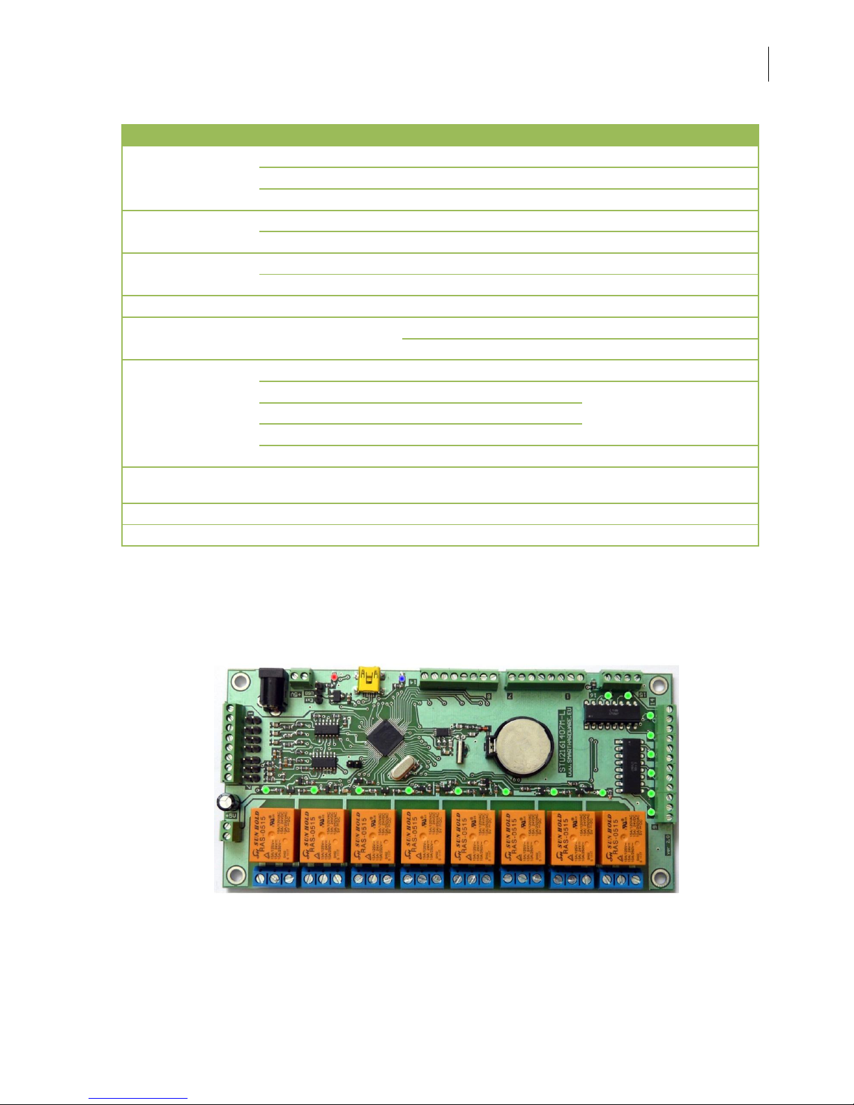
STU2161407M-L
USB programmable controller
Ver. 1.2.2013
Software ver.1.1.2013
SmartHardware
User Guide STU2161407M-L
2
1. Features
HID Device / COM Port select by Jumper
HID Mode
Backup battery (CR2032) for one week RTC
Minimum pulse duration 120ms
Four concurrent conditions for output.
COM Mode
Runtime Counter – 4 bytes
User Data RAM – 4 bytes
Outputs
8
RELAYS 5V - 250V/10A
8
With Optocouplers, I<15mA, V<30V
Digital Inputs
14
0 – 50 V
I input = 250uA
Analog Inputs
7
10bit ADC
0 – 10 V
Rin = 91k, step 0.01 V
0 – 20 mA
Rsh = 500, step 0.02 mA
Power Supply
Single or Double
Con0
+5V
Icc max = 60mA
Con1
+5V
Con2
+5V
Con3
+5V(0.56A)
Dimensions
162 x 80 x 20 mm
Dimensions for
installation
152 x 70 mm
Weight
172 gr.
PC Software
STU2XXXX Assistant / STU2XXXX Assistant Simple
SmartHardware
User Guide STU2161407M-L
3

SmartHardware
User Guide STU2161407M-L
4

SmartHardware
User Guide STU2161407M-L
5
SmartHardware
User Guide STU2161407M-L
6
2. Power
To operate this controller is not necessary a permanent connection to a
computer.
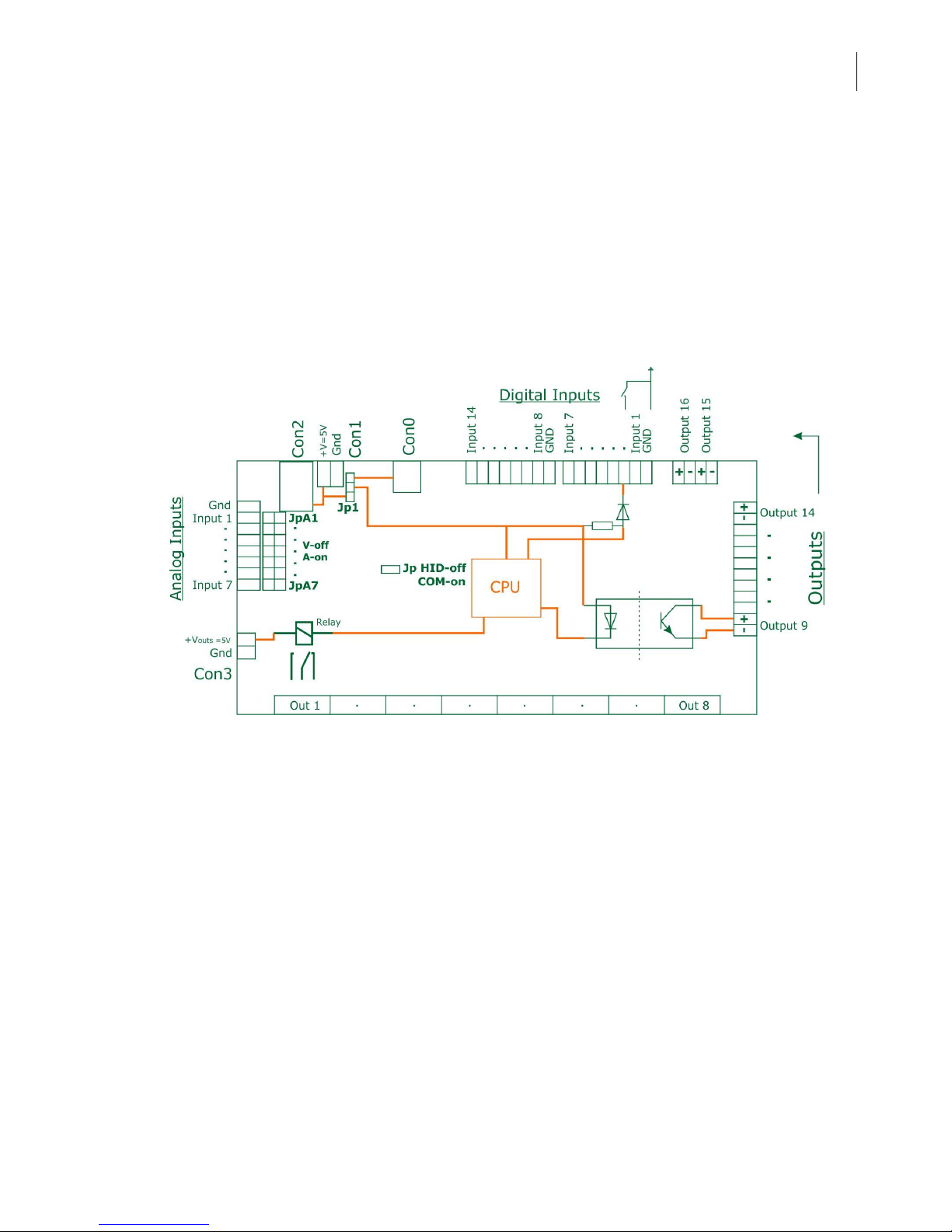
This controller can be powered with single or dual power supply for logic.
Usually using one of Con1 or Con2 for power and Con0 only is used for
programming by computer. Con3 is used only for Outputs with Relays.
This is a block diagram of power:
Backup Battery is used only in HID Device mode. The controller can
operate without it, if it is not needed in both modes.
SmartHardware
User Guide STU2161407M-L
7
3. Digital Inputs
When the input is not connected, it is assumed level H.
Resistance for input must be less than 1200 Ohm.
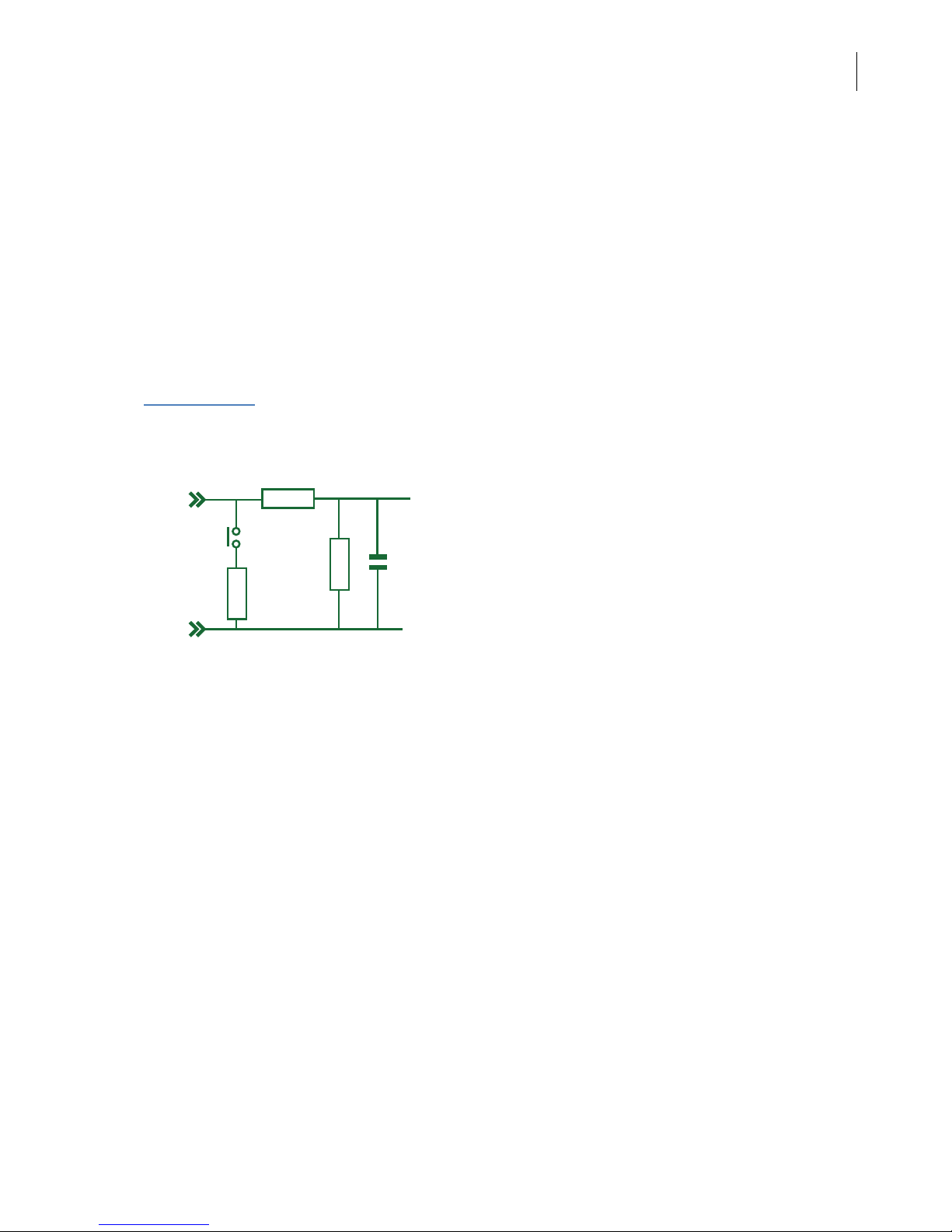
4. Analog Inputs
Input can withstand for a short time higher voltages. The only limitation is heat
over the resistance. When an input is set in the current mode, is a normal
resistance of the input slightly to heat up.
With jumper removed, the input is in the Voltage mode, when placed jumper – Current mode.
To select mode:
1. Set Jumper
2. Select MODE from Software
Input X
Rin=91k
Rs h= 500
JpAX
GND
Uses 10-bit ADC. Result is 0 – 1023(0x3FF).
Voltage mode:
The range is 0 – 10.23 V. Step = 0.01V. Rin = 91k.
Current mode:
The range is 0 – 20.46 mA. Step = 0.02mA. Rsh = 500 ohms.
4. Outputs 1- 8
Outputs are implemented with relays SUN RAS-0515, 10A/250V.
5. Outputs 9- 16
Outputs are implemented with optocouplers LTV847. Current through the LED
is 5 mA.
All inputs and outputs are independent.

SmartHardware
User Guide STU2161407M-L
8
5. Mode, Software for PC and other features
This controller can operate in two modes: HID Device Mode (jumper
removed) and COM Port Mode (jumper placed). Programming in both
modes is independent. Jumper checked only at power on.
Please see USER GUIDE for PC software / STU2XXXX Assistant / for other
features.
-- HID Device Mode --

SmartHardware
User Guide STU2161407M-L
9
-- COM PORT Mode –

SmartHardware
User Guide STU2161407M-L
10
Thank you for using our products. For current versions and
new products seek us at
www.SmartHardware.eu
 Loading...