


SmartHardware
User Guide STR1000008X
1
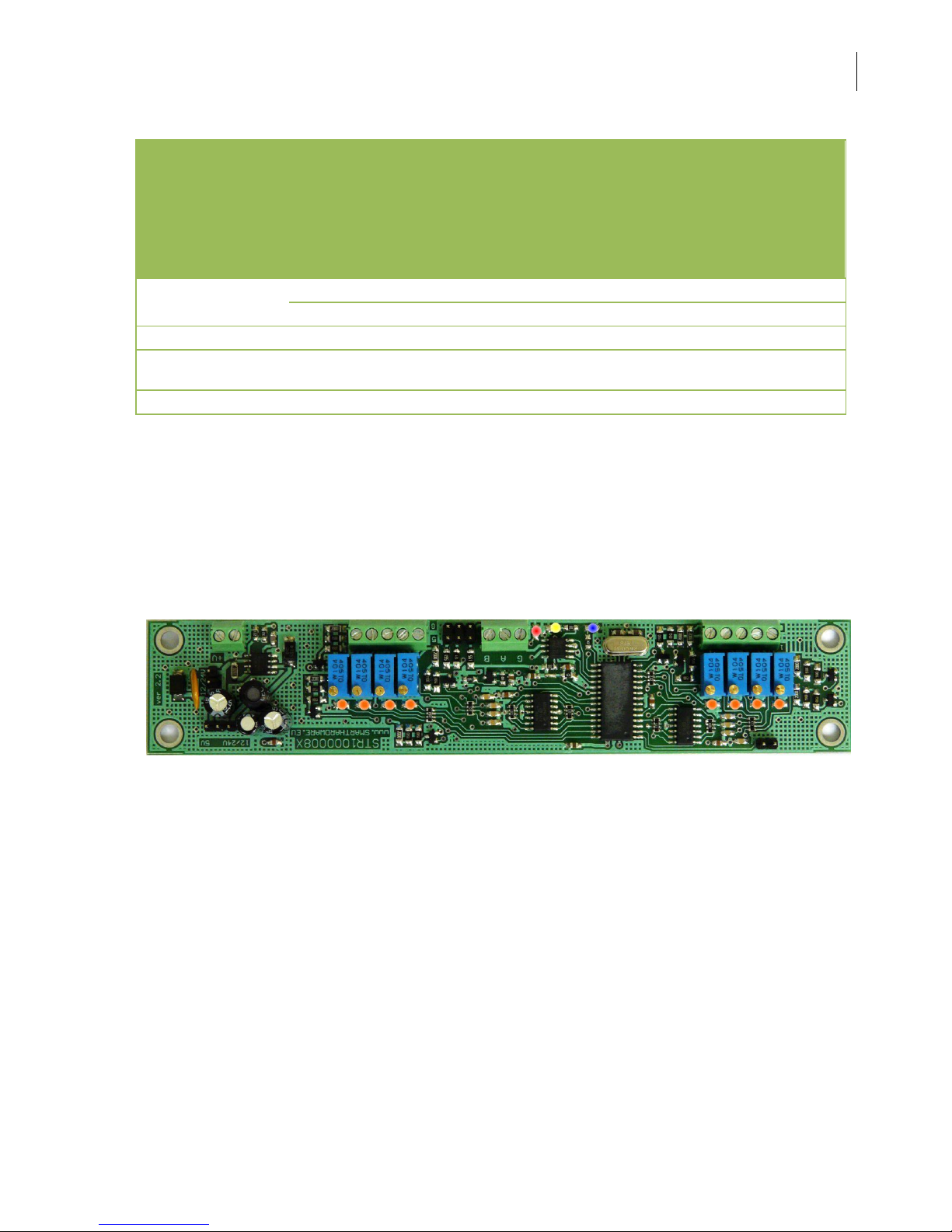
STR1000008X
RS-485
smart programmable controller
Ver. 1.3.2014
Software ver.1.1.2013
SmartHardware
User Guide STR1000008X
2
1. Features
RS-485 smart management line.
Jumper free for switching V/A.
Wide range of baud rate speeds (300 – 115200).
Fully reprogrammable on the fly without restart.
Runtime Counter – 4 bytes
User Data RAM – 4 bytes
User Data EEPROM – 4 bytes
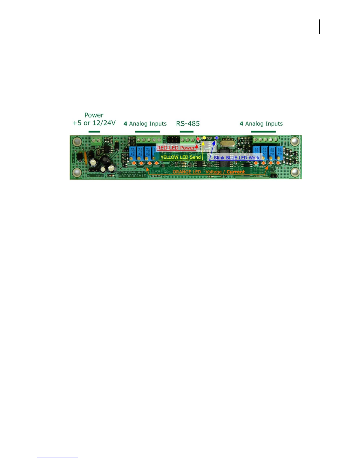
Analog Inputs
8
0 – 10 V
Rin = 91k, step 0.01 V
10bit ADC
0 – 20 mA
Rsh = 500, step 0.02 mA
Power Supply
+5V(30mA) or +9-24V(20mA for 12V)
Dimensions
162 x 31x 20 mm
Dimensions for
installation
152 x 21.5 mm
Weight
38/33gr.
v 2.1
Compared to version v2.0 was added protection for reversal of the power
supply of controller. Changed the scheme of the analog inputs.
SmartHardware
User Guide STR1000008X
3
SmartHardware
User Guide STR1000008X
4

SmartHardware
User Guide STR1000008X
5
v 2.0

SmartHardware
User Guide STR1000008X
6

SmartHardware
User Guide STR1000008X
7
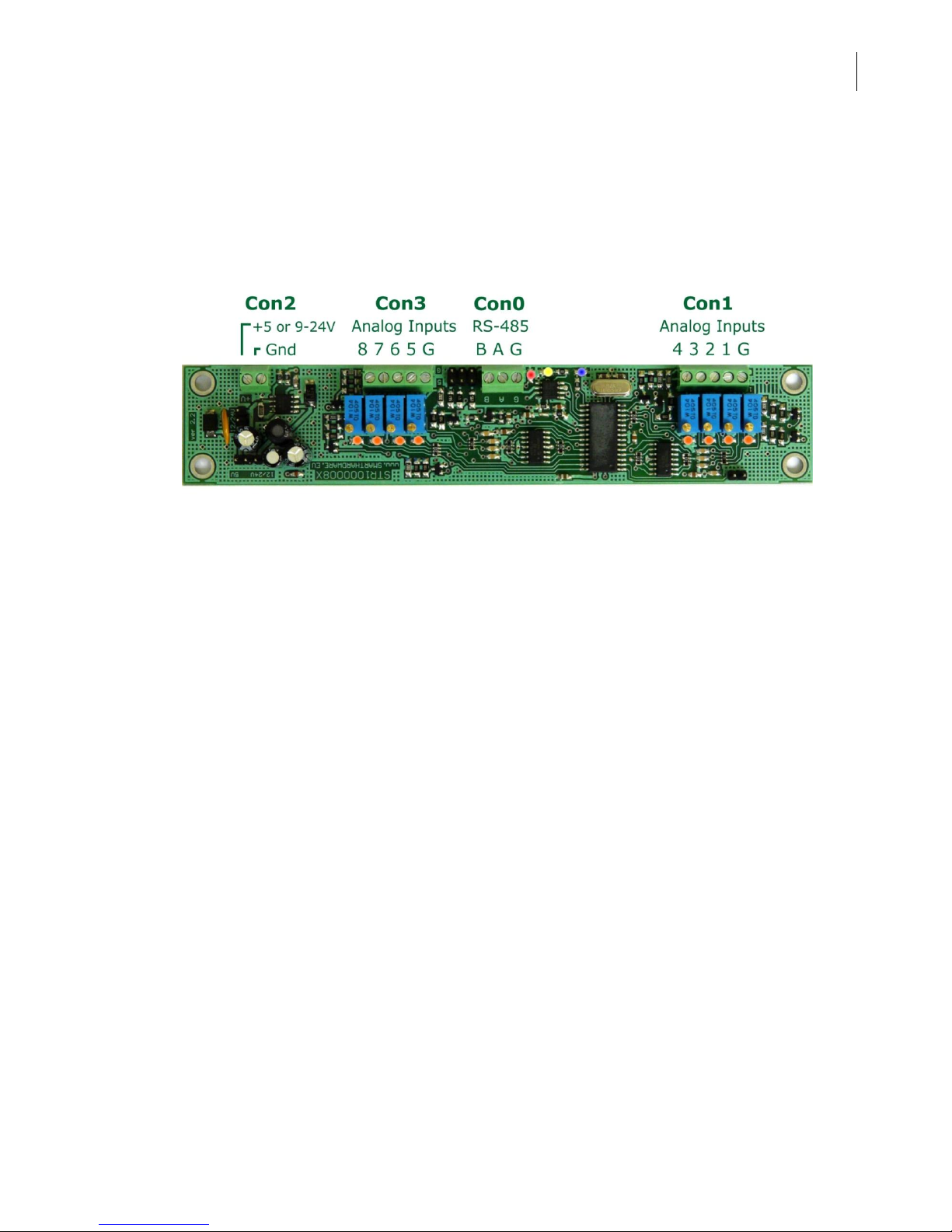
Analog Input 1
Analog Input 5
Analog Input 4
Analog Input 8
GND
GND
V=+5 9-24Vor
Gnd
R1
BA Gnd
R2R3
(560ohm) (560ohm)(120ohm)
+5V
RS-485
Jp1
Jp3
Jp2
JR2
JR2
JR1
JR1
JR3
JR3
RS-485
CPU
9-24V to 5V
B A G
+5V
(Load Defaults)
. .. .

SmartHardware
User Guide STR1000008X
8
2. Power
This controller can be powered from +5V, +12 or +24V. Use Jp1 and Jp3 to
select voltage.
Power = +5 V
Power = +12/24 V
Jp2 is used to load all default parameters.
Disconnect power. Put jumper. Connect power. The blue LED will light
constantly. Now controller waits to remove jumper. Remove jumper. The
controller will continue in normal mode. The blue LED will flash briefly.
Check the PDF file with commands for a full explanation – page 3.
IMPORTANT: Do not change jumpers for power, when voltage for power is applied to the
controller. The controller is powered by a switching converter for 5V. It might pulses, from
switching the jumper to erase the software built into the microcontroller.
Jumpers should be switched ONLY when the controller is powered down!
V=+5V
Gnd
Jp1
Jp3
Jp2
JR2
JR1
JR3
CPU
9-24V to 5V
+5V
(Load Defaults)
V=+9-24V
Gnd
Jp1
Jp3
Jp2
JR2
JR1
JR3
CPU
9-24V to 5V
+5V
(Load Defaults)

SmartHardware
User Guide STR1000008X
9
3. RS-485 line
This controller manages the RS-485 line intelligently.
Controller can perform one command while receiving second command.
Unlike any other similar controllers, it checks the correct information,
which returns as result. When controller transmits, simultaneously
read the information transmitted from RS-485 line. Each byte is
compared for validity. When an error is detected, transmission is
terminated. This helps to quickly release the line. In case of a short
circuit on the line, the transmitter is protected against overload.
Baud rate (300 – 115200)
At any time you can set new speed. The next command already is taken on
new speed. There is no need to reboot the controller.
R1, R2, R3 for RS485 line
By default, this controller comes with a transmitter SN75176. This transmitter
has an input 1 unit load (12k ohms). By default, the line must be terminated
with two resistors of 120 ohms at both ends. You can connect up to 32
controllers.
R1 and R3 must be calculated according line. Into account, must take the
resistance of the wires.
By default, R1=R3=560 ohms. R2=120 ohms. When jumper set, resistor
connected to line.
How to calculate the values of R1 and R3 with 120 ohm resistors at both ends.
Example: 10 controllers and 5 V supply.
Each RS-485 node has a load impedance of 12K ohms. 10 nodes in parallel
give a load of 1200 ohms. Additionally, the two 120 ohms termination resistors
result in another 60 ohms load, for a total load of 57 ohms (1200 and 60 in
parallel). Clearly the termination resistors are responsible for a majority of the
loading. In order to maintain at least 200mV between the B and A line, we
need a bias current of 3.5 mA (200mV/57=3.5mA) to flow through the load. To
create this bias from a 5V supply a total series resistance of 1428 ohms or less
is required. Subtract the 57 ohms that is already a part of the load, and we are
left with 1371 ohms. Placing half of this value as a pullup to 5V and half as a
pulldown to ground gives a maximum bias resistor value of 685 ohms for each
of the two biasing resistors. R1=R3=680 ohms.

SmartHardware
User Guide STR1000008X
10
How to calculate the values of R1 and R3 WITHOUT 120 ohm resistors at both
ends.
Example: 32 controllers and 5 V supply.
Each RS-485 node has a load impedance of 12K ohms. 32 nodes in parallel
give a total load of 375 ohms. In order to maintain at least 200 mV across 375
ohms we need a current of 0.53 mA. To generate this current from a 5V supply
requires a total resistance of 9375 ohms maximum. Since 375 ohms of this
total is in the receiver load, our bias resistors must add to 9K ohms or less.
Notice that very little bias current is required in systems without termination.
R1=R3=4.3K ohms.
Bias resistors can be placed anywhere in the network or can be split among
multiple nodes. The parallel combination of all bias resistors in a system must
be equal to or less than the calculated biasing requirements.
We produce these controllers. For your convenience we can solder
other resistors. We can leave blank the space and you can solder the
resistors that you need. Size is 1206.
3. Analog Inputs
Analog Input can withstand for a short time higher voltages. The only
limitation is heat over the resistance. When an input is set in the current mode,
is a normal resistance of the input slightly to heat up.
v 2.1
V in max = 40 V for T < 2sek
in both modes V/A
You can change input limit with Rin.
For example: 0 - 5V or 0 - 24V.
Analog Input X
V/A
Analog
Rin=100k
R=10k
Rsh=500
GND

SmartHardware
User Guide STR1000008X
11
v 2.0
V in max = 40 V for T < 2sek
in both modes V/A
Uses 10-bit ADC. Result is 0 – 1023(0x3FF).
Voltage mode:
The range is 0 – 10.23 V (default). Step = 0.01V. Rin = 91k / custom.
Current mode:
The range is 0 – 20.46 mA (default). Step = 0.02mA. Rsh = 500 ohms.
5. Commands
Check the PDF file with commands for a full explanation. This controller
supports the following commands ( in HEX ):
1, 2, 3, 8, 9, A, 10, 16, 1B, 20, 21, 22, 23, 32, 33
88, 89, 96, 9B
http://smarthardware.eu/manual/str1xxxxxx_com.pdf
6. Method of connecting to network. Principle of operation.
When operating, the controller uses a buffer of 40 bytes maximum for each
command. While performing a command, it may receive next. Before receiving
the last byte of the second command, the first must be finished. If not, then
the second will be ignored.
When a command is sent to reprogram something, must be borne in mind,
that one byte programming take time approximately 4 milliseconds.
There are built-in protections for the pause between two bytes. The time
between two commands can be arbitrary. After receiving the first byte of the
command, the maximum time to the next byte must be less than 300 ms. If
Analog Input X
V/A
Analog
Rin=91k
Rsh=500
GND

SmartHardware
User Guide STR1000008X
12
this time is greater, all received bytes are rejected and the receiving buffer is
cleared.
How to connect the controller to network.
1. Set (on/off) jumpers for resistor for RS-485 line
2. Power the controller
3. Connect controller to RS-485 line
4. Program new controller number
5. Program new analog inputs number for direct access
6. Program mode ( V/A) for analog inputs
7. Controller is ready for use
8. You can connect next controller …..
You can use any transmitter for the management of this
controller. It is enough to maintain the required speed and input
impedance is complies with the network.
Thank you for using our products. For current versions and
new products seek us at
www.SmartHardware.eu
 Loading...