

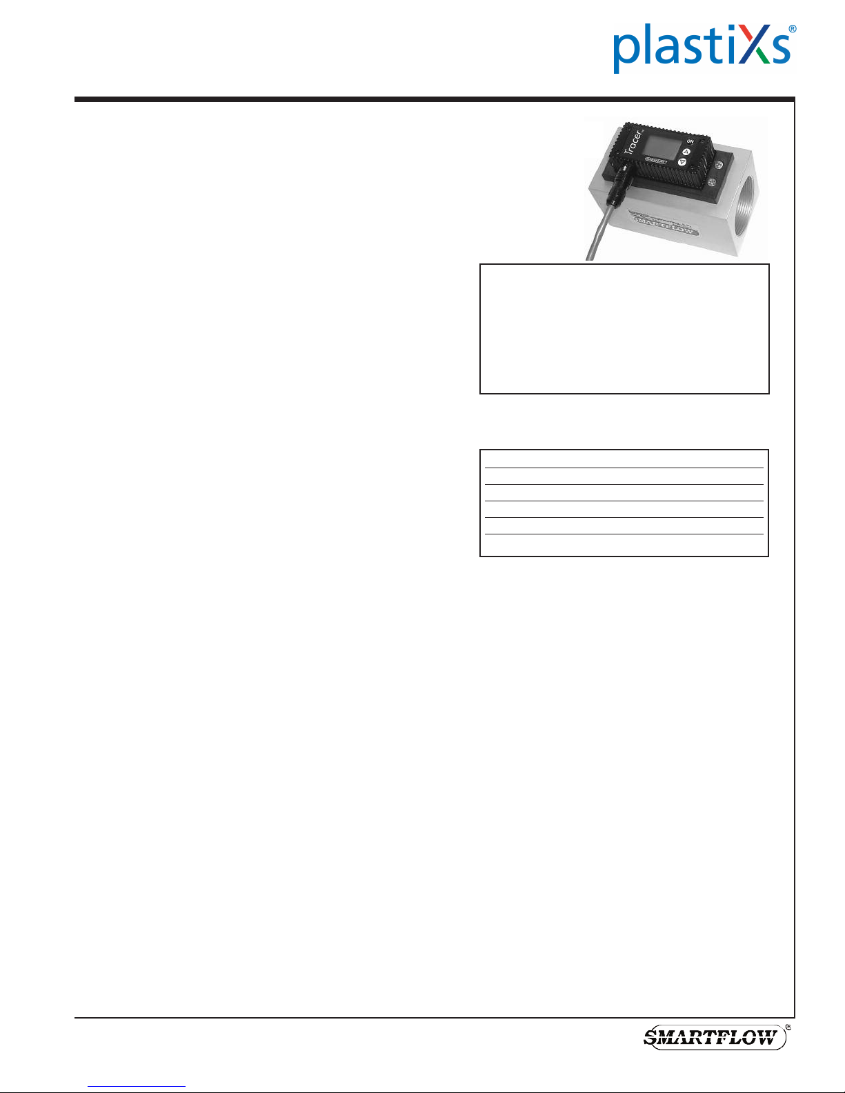
Tracer
Flowmeter
Operating Instructions (Ver 5.1)
®
Electronic Switching
with FCI (Fluid Characteristic Indication)
General
The Tracer Electronic Switching Flowmeter provides:
◆ 0 to 5V or 0 to 10V Selectable Flow Output
◆ 0 to 5V or 0 to 10V Selectable Temperature Output
◆ 1A, 30VAC/42VDC Programmable Switch for high
or low temperature and/or flow
◆ Fluid Flow Rate Display in gallons per minute
(gpm) or liters per minute (lpm)
◆ Fluid Temperature Display (°F or °C)
◆ BTU’s per Minute Display
◆ Fluid Characteristic Indication (Turbulent Flow or
“TFLOW” on display)
BTU Basics
To obtain the most accurate BTU calculation, use the Tracer
to measure the supply side water temperature (in °F) before
installing the Tracer in a cooling water return line.
BTU’s per minute calculation is based on the increase in water
temperature multiplied by the flow rate. The Tracer Electronic
Flowmeter calculates this information based on supply side
temperature entered manually. Due to inherent differences in most
thermometers, the most accurate BTU calculation will result from
using the same thermometer (inside the Tracer) to measure supply
and return line temperatures. Record the supply side temperature and
enter it using the “Set BTU/m Input Temperature” instructions on
page 3.
U.S. Patent No.
7,729,869
Application
Liquid running through the Tracer flowmeter
should be free of metal shavings. Loose
particles can interfere with moving
components causing extra maintenance
requirements.
Specifications
Flow
Size [NPT(F)] Range (gpm) Range (lpm)
3/8" 0.5 to 8 0 to 30
3/4" 2.0 to 20 8 to 76
1" 3.0 to 30 11 to 114
1-1/2" 6.5 to 60 25 to 228
2" 10.0 to 110 38 to 418
Accuracy ....................±5% of Full Range
Repeatability ..............±3% of Full Range
Environment
Tracer construction is water resistant, but the
electronics housing is not submersible.
Turbulent Flow
“TFLOW” notification appears on the display when Turbulent Flow
is likely inside the cooling circuit of the selected size.
Turbulent flow is the mixing and swirling of water inside a cooling
line that provides optimum heat transfer. Water flow rate greater than
the point of Turbulent Flow does not provide a proportional benefit.
Turbulent flow tracking allows technicians to apply mathematical
cooling principles to all machines in a water system. Visit the
Technical Documents section of www.smartflow-usa.com for a
detailed discussion of Turbulent Flow.
Input the percentage of glycol in cooling water (0%, 10%, 20% or
30%) for accurate Turbulent Flow Indication. See Setup Mode option
on page 5. Antifreeze compounds of ethylene or propylene glycol are
sometimes added to cooling waer. Glycol compounds have
substantially higher viscosity than water. As a result, higher flow
rates are required to reach Turbulent Flow when glycol is used.
151 Memorial Drive, Unit H - Shrewsbury, MA 01545 - Phone: (888) 792-2223 - sales@plastixs.com - www.plastixs.com
Form #146 (02.16)
Temperature
Operating Range............32 to 180°F (0 to 82°C)
Accuracy........................±2% of Display Value
Repeatability..................±1% of Display Value
Component Materials
Body (3/8" model) .........Nickel-Plated Brass
Body (3/4" thru 2")........Anodized Aluminum
Stainless Steel (optional)
Back Cover(3/8" only) ..Polysulfone
Impeller..........................Nylon 6/12
Magnet...........................Neodymium
Shaft...............................18-8 Stainless Steel
Electronics Cover ..........Nylon 6/6
Cable..............................9-Conductor, 24AWG
Operating
Internal Relay ................SPDT 1A, 30VAC/42VDC
Power Required .............8 to 28VDC
Maximum Pressure........100psi (7bar)
Installation Instructions
For best performance, mount the Tracer flowmeter vertically with the
flow entering the meter from the bottom. This provides full flow inside
the meter. We recommend a straight run of pipe equal to 10 pipe
diameters on the inlet side of the Tracer flowmeter and a straight run of
pipe equal to 5 pipe diameters on the outlet side of the flowmeter.
Use appropriate pipe sealant to prevent leakage on inlet and outlet
sides of the flowmeter. The Tracer flowmeter can be installed in any
orientation with the flow direction from either end of the flowmeter.
Attach the power and switching connections to the bare wires of the
cable according to the chart at right. Individual wires are 24AWG
stranded copper. Attach 8 to 28VDC power to the unit for correct
operation. Power supply other than 8 to 28VDC may damage the
electronics!
In normal operation, the internal relay is energized. If power to the unit
is lost, or if unit is turned off, relay state changes to signal an alarm.
Operating Instructions
When power is applied to the Tracer flowmeter, the software version
and the Tracer Unit Code (EP) will appear sequentially. Then the
screen will be blank. Press ON to activate the display.
There are three modes of operation for the Tracer Electronic
Flowmeter: User Mode, Setup Mode, and Calibration Mode. User
Mode displays all available process information. Setup Mode
configures the flowmeter for unit selection (°F, °C, lpm, and gpm)
and switching set points. Setup Mode also allows you to enter the
information required to calculate BTU’s per Minute.
Wire Color Function
Black DC Ground
(Ground for Analog Output)
Yellow +DC Input (8 to 28VDC)
Red Not used
Blue Not used
Orange Flow Analog Voltage Output (+)
Violet Temp. Analog Voltage Output (+)
Green Relay Common
Brown Relay Normally Open
Gray Relay Normally Closed
Figure 1
ON
Δ
Δ
User Mode
After pressing ON, press Δ or ∇ buttons repeatedly
to scroll continuously through displays of flow
rate, temperature and BTU/m. BTU/m will not
display until activated using the Setup Mode on
page 3.
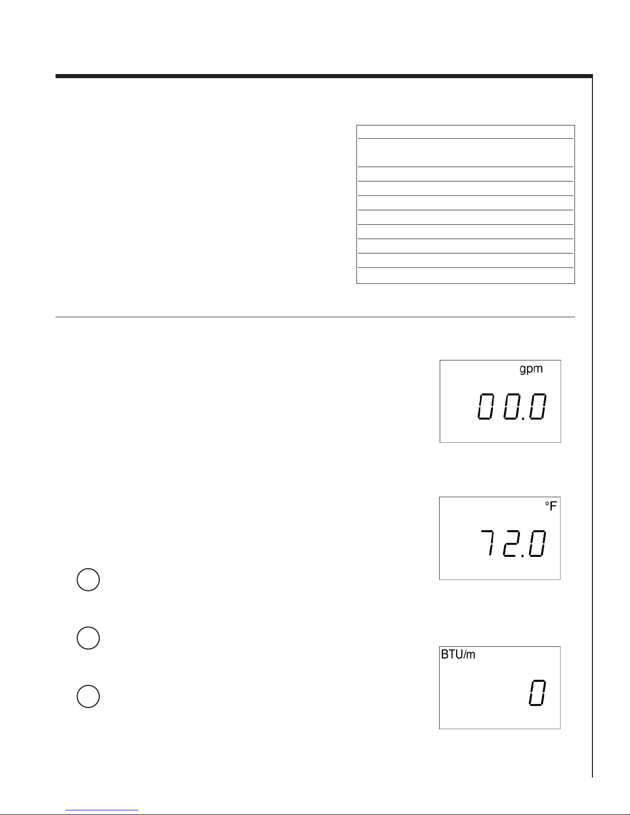
View Flow Rate
Press ON. Flow rate and units (gpm or lpm) will be
displayed. See Figure 1.
View Temperature
Press Δ. Temperature and units (°F or °C) will be
displayed. See Figure 2.
View BTU/m (not visible until activated)
Press Δ. BTU's and units will be displayed. See
Figure 3. To activate, enter Setup Mode, and
follow instructions to set input temperature found
on page 3.
Figure 2
Figure 3
2
Setup Mode
Setup Mode allows the user to select English or Metric units, input
BTU/m inlet temperature, and set auto shut-off time. Δ and ∇ keys
scroll through all options inside each display selection. Turn the
display off before entering Setup Mode.
Enter Setup Mode
The display must be off to enter Setup Mode.
∇
and
Press and hold ∇, then press ON. Flow rate units
ON
plus "Unit" and "SETUP" will be displayed. See
Figure 4.
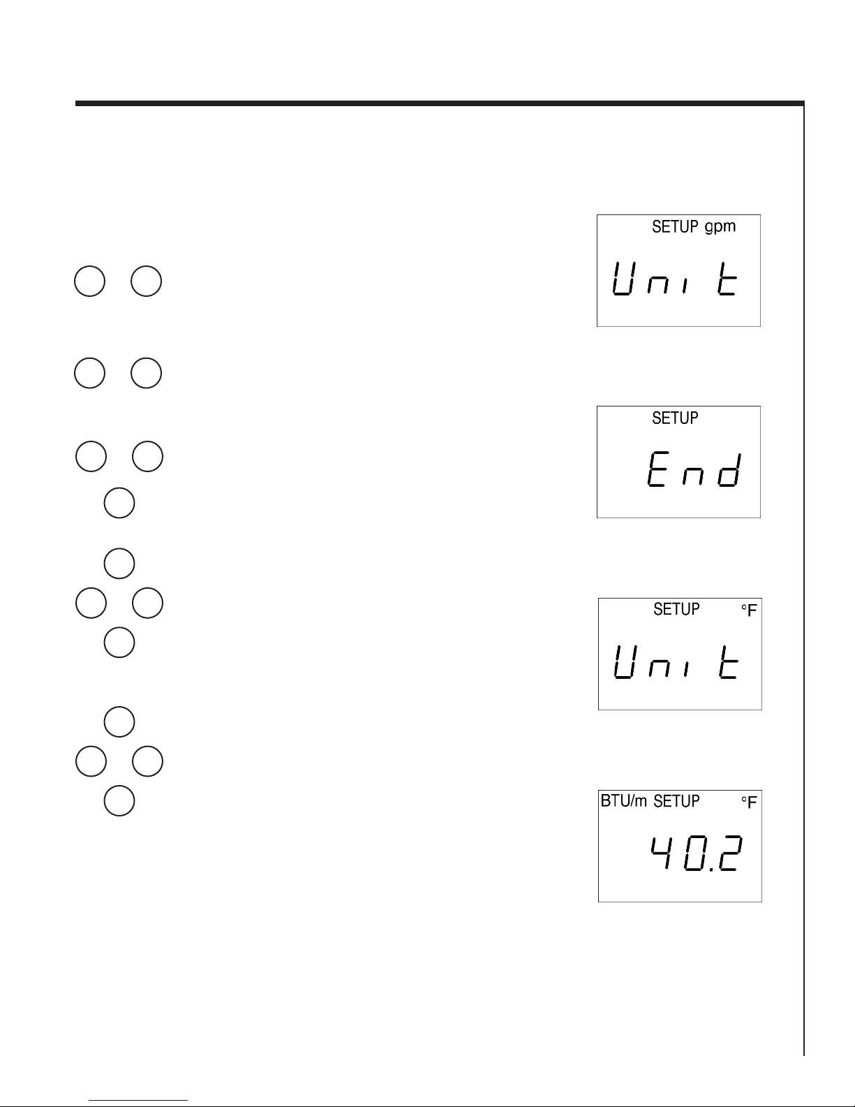
Select Flow Rate Units
Figure 4
∇
ON
∇
∇
or
ON
ON
or
ON
ON
or
ON
Press ∇ or Δ to change units to gpm or lpm. Press
Δ
ON when the desired unit is displayed. See Figure
4. Setup Mode will continue unless you exit.
Exit Setup Mode
Δ
Press ON repeatedly until the display reads “end”,
then press Δ. See figure 5. The display will read
"off", then press ON and the unit will return to user
mode.
Select Temperature Units
Enter Setup Mode (above). Press ON repeatedly
until the display shows “°F” or °C” in the upper
right corner and “unit” in the center. See Figure 6.
Δ
Press ∇ or Δ to change units. Press ON when
desired unit is displayed.
Setup Mode will continue unless you exit.
Set BTU/m Input Temperature
Enter Setup Mode (above). Press ON repeatedly
until the display shows “BTU/m” in the upper left
corner. See Figure 7. Press ∇ or Δ to change input
temperature (40 to 220°F or 4.4 to 104.4°C). Press
Δ
ON when desired unit is displayed.
Note: If you set the temperature input to less than
40°F or 4.4°C, the display will show “off” and
BTU/m display will deactivate.
Setup Mode will continue unless you exit.
Figure 5
Figure 6
Reactivate BTU/m
Follow the instructions to set (above) and press ∇
or Δ to display a value instead of “off”, and press
ON to set.
Figure 7
3
Switch Set Points
All switch set points are turned off when shipped from the factory. The switch actuates when sensed value(s) fall below
low level set point(s) and/or sensed values rise above high level set point(s). The switch returns to normal state when the
process fluid reaches programmed flow and/or temperature conditions. There is a 2 second delay to prevent switch chatter.
Any or all of the switches may be disabled or enabled at any time. An internal programming check prevents conflicting low
and high switch values. Always set the flow switching points using the same units as normal operating units.
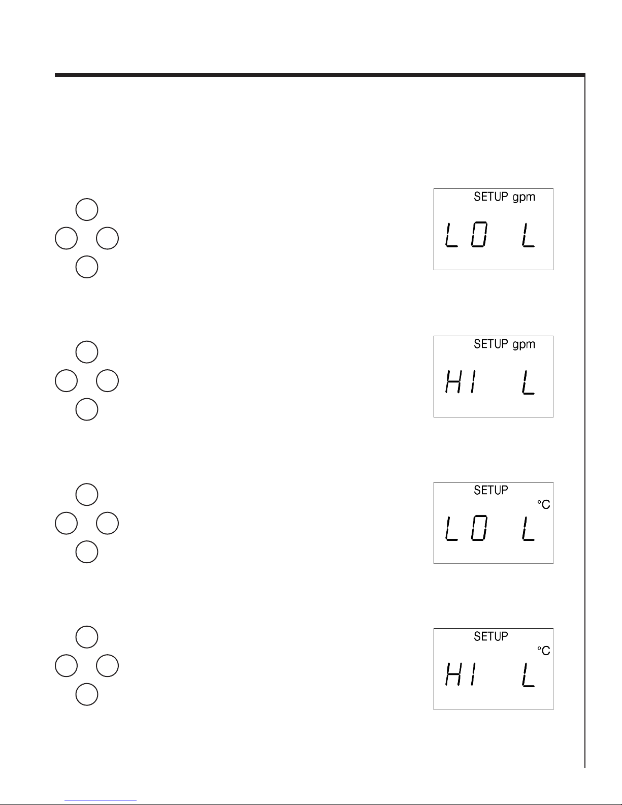
Set Lo Limit Flow Switch Point
∇
∇
∇
ON
or
ON
ON
or
ON
ON
or
ON
Enter Setup Mode (see page 3). Press ON
repeatedly until the display shows “gpm” or “lpm”
in the upper right corner and “LO L” in the center.
See Figure 8. Press ∇ or Δ to set the flow rate at
Δ
which the Normally Open switch contact will
close. Press ON when desired value is displayed.
To turn off this set point, press and hold ∇ until the
display shows “OFF”.
Setup Mode will continue unless you exit.
Set Hi Limit Flow Switch Point
Enter Setup Mode (see page 3). Press ON
repeatedly until the display shows “gpm” or “lpm”
in the upper right corner and “HI L” in the center.
See Figure 9. Press ∇ or Δ to set the flow rate at
Δ
which the Normally Open switch contact will
close. Press ON when desired value is displayed.
To turn off this set point, press and hold Δ until the
display shows “OFF”, and press ON to set.
Setup Mode will continue unless you exit.
Set Lo Limit Temperature Switch Point
Enter Setup Mode (see page 3). Press ON
repeatedly until the display shows “°F” or “°C” in
the upper right corner and “LO L” in the center.
Δ
See Figure 10. Press ∇ or Δ to set the temperature
at which the Normally Open switch contact will
close. Press ON when desired value is displayed.
To turn off this set point, press and hold ∇ until the
display shows “OFF”.
Setup Mode will continue unless you exit.
Figure 8
Figure 9
Figure 10
Set Hi Limit Temperature Switch Point
ON
or
∇
ON
Enter Setup Mode (see page 3). Press ON
repeatedly until the display shows “°F” or “°C” in
the upper right corner and “HI L” in the center. See
Figure 11. Press ∇ or Δ to set the flow rate at
Δ
which the Normally Open switch contact will
close. Press ON when desired value is displayed.
To turn off this set point, press and hold Δ until the
display shows “OFF”, and press ON to set.
Setup Mode will continue unless you exit.
Figure 11
4
Set Flow Rate Display Filter
∇
∇
ON
or
ON
ON
or
ON
The Tracer flowmeter impeller changes speed as
the water is swirling and mixing while passing
through the meter. The filter program stabilizes the
Δ
display reading for the meter by averaging readings
from the impeller. Filter can be turned ON or OFF.
The recommended setting is ON.
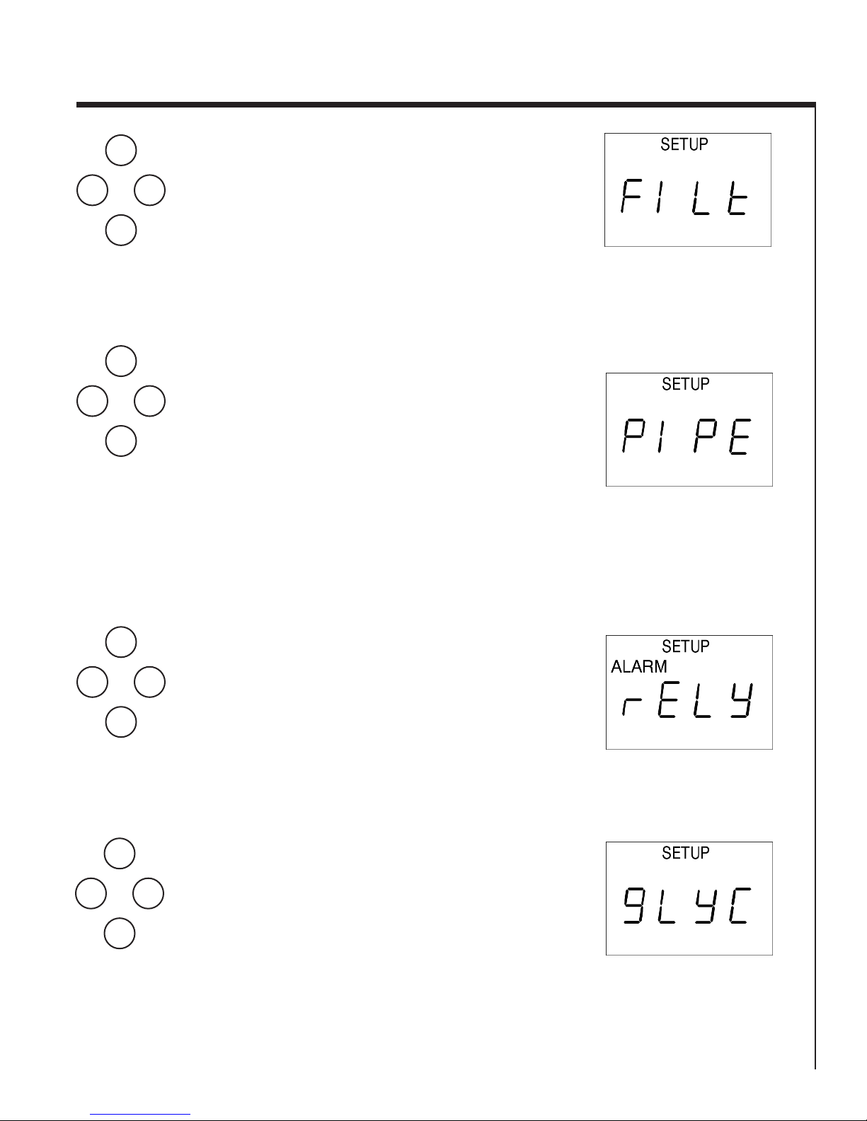
Enter the Setup Mode (see page 3). Press ON
repeatedly until the display reads “Filt” (see figure
12) Press ∇ or Δ to toggle the filter setting ON or
OFF.
Change Cooling Line Size (Turbulent Flow)
Enter Setup Mode (see page 3). Press ON
repeatedly until the display shows “PIPE” (see
Δ
Figure 13). Press ∇ or Δ to change cooling line
size. Available sizes are: 0.250
0.375
0.750
1.000
1.500
2.000
Turbulent Flow display “TFLOW” and calculation
are adjusted automatically based on process
temperature and pipe size.
Figure 12
Figure 13
∇
∇
ON
or
ON
ON
or
ON
Select Relay Action to Set Points or
Turbulent Flow
Relay can be set to switch on user programmed set
points or on Turbulent Flow. Enter Setup Mode
(see page 3) Press ON repeatedly until the display
shows “rELY” (see Figure 14). Press ∇ or Δ to
Δ
change relay action to “ALARM” or “TFLOW”.
Alarm settings are programmed per instructions on
page 4 and are held in memory if “TFLOW”
setting is used. Factory default setting is
“ALARM”
Select Percentage of Glycol
Enter the percentage of glycol present for accurate
Turbulent Flow “TFLOW” Indication. Higher flow
rate is required to achieve Turbulent Flow when
glycol is present.
Δ
Enter Setup Mode (see page 3). Press ON until the
display shows “GLYC” (see Figure 15). Press ∇ or
Δ to indicate the correct glycol percentage: 0, 10,
20, or 30%. Press ON to set.
Figure 14
Figure 15
5

Analog Output Options
Output Voltage for flow and temperature are set independently. 0 to 5V or 0 to 10V output is selectable for flow or
temperature. The upper end of the effective flow range is also user-definable to give a more accurate flow and temperature
reading over the voltage output range. For Example: In a 1" cooling line you are using only half of the flow range. The
Tracer flowmeter can be set for 10V output at 15gpm instead of 30gpm to provide more precise voltage output.
∇
∇
∇
ON
or
ON
ON
or
ON
ON
or
ON
Select Flow Voltage Output
Enter Setup Mode (see page 3). Press ON
repeatedly until the display shows “AO F” (Analog
Δ
Output Flow) in the center. See Figure 16. Press ∇
or Δ to set 5 or 10 Volts as the upper end of the
output range. Press ON when desired value is
displayed.
Select Temperature Voltage Output *
Enter Setup Mode (see page 3). Press ON
repeatedly until the display shows “AO t” (Analog
Output Temperature) in the center. See Figure 17.
Δ
Press ∇ or Δ to set 5 or 10 Volts as the upper end
of the output range. Press ON when desired value
is displayed
Set Flow Output Upper Limit
Enter Setup Mode (see page 3). Press ON
repeatedly until the display shows “FS F” (Full
Δ
Scale Flow) in the center. See Figure 18. Press ∇
or Δ to set the upper limit of the flow output. Do
not set this value higher than the largest flow value
of the meter. Press ON when desired value is
displayed.
Figure 16
Figure 17
Figure 18
Set Temperature Output Upper Limit *
ON
or
∇
ON
Enter Setup Mode (see page 3). Press ON
repeatedly until the display shows “FS t” (Full
Δ
Scale Temperature) in the center. See Figure 19.
Press ∇ or Δ to set the upper limit of the
temperature output. Press ON when desired value
is displayed. Setup Mode will continue unless you
exit.
* Note: The low end of temperature output range =
0°F (-17.8°C)
Figure 19
6
Calibration Mode
Calibration Mode allows the user to adjust the calibration values for
flow and temperature. Other functions include LCD self-test. There
are eight functions or displays available through this mode. The ON
button scrolls the menu through all functions until the user turns the
display off.
Turn the display off before entering Calibration Mode.
∇
hold
Δ
then
ON
ON
ON
ON
or
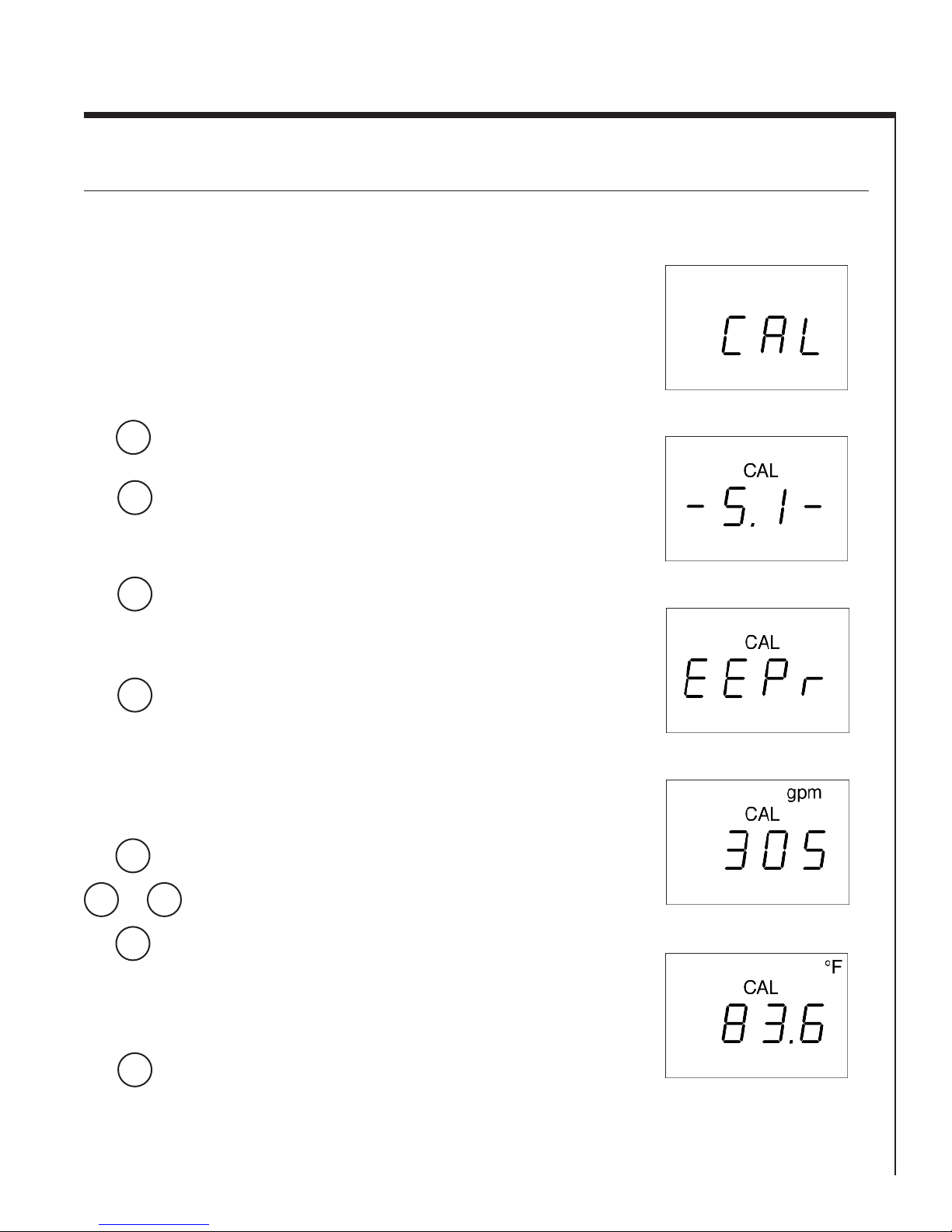
Start Calibration Mode
The display must be off to enter this mode. Press
and hold Δ, then press ON. CAL will be displayed.
See Figure 20. To scroll through the Calibration
Mode, press the ON button. If the ON button is not
pushed within three seconds, the display will
automatically shut off.
Software Version
By pressing ON once after entering Calibration
Mode, the software version will display. See Figure
21. There is no adjustment to be made.
EEPR
This function resets the calibration values to the
program defaults. See Figure 22. Do not reset
these values! This will re-program the Tracer
flowmeter back to pre-calibrated settings. The
flowmeter must be recalibrated if this is done.
Flow Calibration Value
Increase or decrease this number by using the
arrow keys. See Figure 23. Increasing the
calibration value by 20 units lowers the flow
display by .1 gpm. See the Flow Calibration
Procedure below.
Δ
Figure 20
Figure 21
Figure 22
Figure 23
ON
ON
Temperature Calibration Value
Increase or decrease this number by using the
arrow keys. See Figure 24. Increasing the
calibration value by 10 units raises the temperature
display by 1 degree F.
Temperature Slope Calibration Value
Do not adjust.
Figure 24
7

∇
ON
or
ON
Analog Output Calibration
This calibration compensates the output for
tolerances of electronic components. Analog
Output Calibration sets the upper end of the
temperature and flow output at exactly 10 Volts.
Flow (See Figure 25): Connect the Orange wire to
the + side of a voltmeter and the Black wire to
ground connection. Adjust the number on the
Tracer flowmeter using the arrow buttons until the
Δ
voltmeter reads exactly 10 Volts. Press the ON
button to scroll to the next function.
Temperature (See Figure 26): Connect the Violet
wire to the + side of a voltmeter and the Black
wire to ground connection. Adjust the number on
the Tracer flowmeter using the arrow buttons until
the voltmeter reads exactly 10 Volts. Press the ON
button to scroll to the next function.
LCD Test Screen
Figure 25
Figure 26
∇
∇
or
ON
or
ON
See Figure 27. By pushing either arrow button,
Δ
“test” will display. By pushing the ON button
while “test” is displayed, the LCD will run a selftest. See Figure 28 for LCD diagram.
End Screen
By pressing either arrow button the display will
Δ
change to “OFF”. Press the ON button to turn off
the display.
Flow Calibration
Procedure
Tools Required:
Five Gallon (minimum) Calibrated
Container (or weigh on an accurate
scale)
Stopwatch
Valved Water Supply
Figure 27
Figure 28
See Figure 29 for an example of the
test configuration.
Figure 29
8

Flow Calibration Procedure (continued)
Before you begin: Purge all the air from the system by running liquid
through the test apparatus.
For best results, take readings as close to full range as possible (at least 5
gpm for the 3/8"NPT, etc.).
1. If the display is off, push the ON button on the Tracer flowmeter.
2. Turn valve to full open position quickly and start timer
simultaneously.
3. Record flow display on the Tracer flowmeter.
4. When the liquid reaches the selected level in the container, stop
timing and close the valve.
5. Divide the volume from the container by time in minutes from the
timer to determine flow rate.
6. Plug the numbers into the following formula:
Tracer reading - manual reading = difference
Multiply the difference x 200.
7. Add the resulting number (positive or negative) to the Flow
Calibration Value in the Calibration Mode. Use the Calibration Mode
to change the flow calibration value, as shown on page 7.
8. Verify and reapt calibration if needed.
Temperature Calibration Procedure
Tools Required:
Accurate Temperature Measuring Device
Water Supply
See Figure 30 for an example of the test
configuration.
Temperature calibration must be
performed with liquid flowing through
the Tracer flowmeter.
1. Stabilize the temperature by allowing
water to run through the circuit for a
few minutes.
2. Press ON on the Tracer Flowmeter, then Δ to display the temperature.
3. Record the temperature shown.
6. Plug the numbers into the following formula:
Measuring device reading - Tracer Flowmeter reading = difference
Multiply the difference x 10.
7. Add the resulting number (positive or negative) to the Temperature
Calibration Value in the Calibration Mode. Use the Calibration Mode
to change the temperature calibration value, as shown on page 7.
8. Verify that Tracer agrees with calibration thermometer and repeat
calibration procedure if needed.
Figure 30
9

Maintenance Instructions
Calibration
Annual calibration is recommended. Return to the factory for calibration, or follow the
Flow and Temperature Calibration Procedures on pages 8 and 9.
Caution: Do not blow compressed air through the flowmeter. Damage to
the rotor and shaft may result.
Drain liquid from inside Tracer flowmeter when not in use to prevent build-up of scale
and mineral deposits.
Copper Plumbing Alert
DO NOT connect an aluminum body flowmeter directly to copper plumbing. Galvanic
corrosion is very likely to occur. Stainless steel body material is strongly recommended
for this application. Contact the factory for more information.
EMI/RFI
Electromagnetic Interference or Radio Frequency Interference may impair the proper
operation of the Switching Tracer. If the unit unexpectedly turns itself off, check the
area around the cable and electronic unit for pumps, heaters and electrical relays that
may emit EMI/RFI. Move the cable and electronic housing away from Thermal
Control Units, Heater Bands, Pumps, etc. If the problem persists, contact the factory.
Chemical Compatibility
The following is a list of chemicals that are not compatible with the
UDEL Polysulfone used in the Tracer Electronic Flowmeter. Contact
Burger & Brown Engineering for more detailed information.
Please contact us for further information.
Burger & Brown Engineering, Inc.
4500 E 142nd Street
Grandview, MO 64030
Tel: 816-878-6675
Fax: 816-878-6683
www.smartflow-usa.com
Limited Warranty
Seller warrants that this product supplied will conform to the description herein stated and that the product will be of standard quality.
This is the sole warranty made by Seller with respect to this product. Seller expressly disclaims any other express or implied warranties,
including, but not limited to, the implied warranty of merchantability and the implied warranty of fitness for a particular purpose.
Seller shall not be liable for any cost or damages, whether direct, incidental or consequential, including, but not limited to, any injury,
loss or damage resulting from the use of this product, regardless of whether any claim for such cost or damages is based on warranty,
contract, negligence, tort or strict liability. The sole liability of Seller is limited to repairing or replacing this product.
this warranty shall not apply to any products that have been repaired or altered by anyone other than Seller. The warranty shall not apply
to any products subject to misuse due to common negligence or accident, nor to any products manufactured by Seller which are not
installed or operated in accordance with the printed instructions of Seller or which have been operated beyond the rated capacity of the
goods. Seller states that the product’s useful safe life is 5 years. Actual life may vary widely depending on operating environment such as
temperature, pressure, and chemical exposure. Users are cautioned to refer to instructions for operating limits and a partial list of
incompatible chemicals.
Acetone, Methyl Ethyl
Ketone
Benzene
Carbon Tetrachloride
Chlorobenzene
Chloroform
Cyclohexanone
Esters
Freon TA
Methylene Chloride
Tetrachloroethylene
1,1,2,2-
Tetrachloroethane
Toluene
1,1,1-Trichloroethane
Trichloroethylene
Xylene
10
 Loading...