


SmartEv Scatalo
INSTALLATION MANUAL
3.7 kW | 7.4 kW | 11kW | 22kW
A unifi ed and consistent use of these guidelines is one of the
key ways by which we will visibly distinguish and strengthen the
equity and hence the value of our brand over the medium and
long-term.
These guidelines are designed to help everybody involved
in the production of our communications and they also play
an important role in building our brand. Please take time to
read and understand them: The design principles have been
carefully considered and developed to ensure that our visual
identity is always consistent. They will continue to evolve as our
requirements grow to become a fully comprehensive guide for
all identity applications.
Thank you for choosing
SmartEv Scatalo charger.
Welcome to the award
winning world of SmartEv.
If you require any further
help and advice when
installing this product,
please call our helpline on
01707 443179.
(Lines are open Monday to
Friday from 7am to 4:30pm).
2
www.smartev.co.uk | 01707 443 179
General notes
At various points in this manual you will see notes and precautionary
warnings regarding possible hazards. The symbols used have the following
meanings:
Warning !
Indicates a potentially hazardous situation which, if not
avoided, could result in death or serious injury.
Caution !
Indicates a potentially hazardous situation which, if not
avoided, may result in minor or moderate injury.
Attention !
Indicates a situation which, if not avoided could result
in property damage.
ESD
This symbol reminds you of the possible consequences of
touching electrostatically sensitive components.
Notice
Notes on use of equipment and useful practical tips are
identifi ed by “i”. Notices do not contain any information that
draws attention to potentially dangerous or harmful functions.
Technical Specifi cations
Scatalo 3,7kW Scatalo 7,4kW Scatalo 11kW Scatalo 22kW
230V AC ~ 50Hz 230V AC ~ 50Hz 3x400V AC ~ 50Hz 3x400V AC ~ 50Hz
3,7kW (16A) P+N+PE 7,4kW (32A) P+N+PE 11kW (16A) 3P+N+PE 22kW (32A) 3P+N+PE
Standby power - 4W Standby power - 4W Standby power - 4W Standby power - 4W
3
www.smartev.co.uk | 01707 443 179
5 safety rules
– Shut down all poles and all sides!
– Secure against reactivation!
– Check that the equipment is voltage-free!
– Ground and short-circuit!
– Cover adjacent live parts and restrict access to
hazardous areas!
Electrical hazard!
The installation, commissioning and maintenance of the
charging station may only be performed by correctly
trained, qualifi ed and authorized electricians who
are fully responsible for the compliance with existing
standards and installation regulations.
– Only supply the terminals from 3 phases 230V with
grounded sources!
– Before commissioning, check all screw and terminal
connections for fi rm seating!
– The connector panel cover may never be left open
unattended. Mount the connector panel cover if you
leave the charging station.
– Use of the charging station with open cable insertion
openings is prohibited.
– Do not carry out any unauthorized conversion work
or modifi cations to the charging station!
– Repair work to the charging station is not permitted
and may only be performed by the manufacturer
(replacement of the charging station)!
– Do not remove any notices on the device, such
as safety symbols, warning notices, rating plates,
nameplates or cable markings!
– Observe the instructions given for selecting the
location and the constructional requirements!
– If the specifi cations for the location are not
observed, this can result in death, serious physical
injury or equipment damage if the corresponding
precautionary measures are not met!
Pull the charging cable only at the plug and not at the
cable out of the connector.
Ensure that the charging cable is not mechanically
damaged (bent, pinched or run over) and the
connection area does not come into contact with heat
sources, dirt or water.
Important Information
Safety Instructions
Not observing the safety instructions can
result in risk of death, injuries and damage
to the device!
SmartEv assumes no liability for claims
resulting from not observing these safety
instructions.
4
www.smartev.co.uk | 01707 443 179

Risk of damage!
Make sure that the charging station is
not damaged by improper handling
(anchoring, housing cover, socket,
inner parts etc.).
– Do not open the lid of terminal in
the rain!
Risk of damage to housing
– Use only detergents dedicated for
anodised aluminium / plexi
– Do not tighten the mounting
screws with force.
– Electrostatically sensitive
components
Risk of damage!
– Electronic components can be
destroyed if touched!
– Before handling components,
make sure you perform an
electrical discharge by touching a
metallic, grounded object!
Installation manual ver. 1.6, © Guide 3
Information for technicians who are permitted to open the device
SmartEv Scatalo is a charging terminal for outdoor area
at which electrically operated vehicles can be charged.
Two vehicles can be charged at the same time, with 3
phases, 32A and maximum 22kW power.
The charging station is designed for installation on a
pavement mounted column.
The respective national regulations must be observed
with regard to the installation and connection of the
charging terminal.
The intended use of the device always includes the
compliance with the environmental conditions for which
this device was developed.
The device was developed, manufactured, inspected
and documented in compliance with the relevant
safety standards. Therefore, the products do not
pose any danger to the health of persons or a risk of
damage to other property or equipment under normal
circumstances, provided that the instructions and safety
precautions relating to the intended use are properly
observed.
The instructions contained in this manual must be
followed precisely in all circumstances.
Failure to do so could result in the creation of potential
sources of danger or the disabling of safety devices.
Apart from the safety instructions given in this manual,
the safety precautions and accident prevention
measures appropriate to the situation in question must
also be observed.
Only electrical vehicles or their chargers may be
connected. A connection of other loads (e.g. electric
tools) is not permitted!
5
www.smartev.co.uk | 01707 443 179

Before Installation
This document describes how to install SmartEv
Scatalo charging station. Before any installation work is
performed, study all drawings furnished by the supplier
for the particular installation.
Safety Requirements
Ensure that at all times when working, no power is
connected.
Eye protection with appropriate glasses (especially
when using the electrical drill).
In the installation be sure to not connect directly to
power distribution network cables without additional
protection.
Use appropriate tools for each function.
Delivery content – packages
Charging station is delivered to a client contains:
Case made with aluminium profi les and plexi glass,
connection for 1x230V 16A (1P+N+PE) or 1x230V 32A
(1P+N+PE) or 3x400V 16A/32A (3P+N+PE) depends
on version, and cover with two security screws - fi g.1
(lenght of chargers depends on version).
Key for security screws 2 RFID cards, 2 RFID key
holders (not included in Scatalo with button).
Upon receipt of shipment, examine the package for
damage. If the shipping container must be opened
outdoors, take proper precautions to prevent the
entrance of moisture.
Installation Guidelines
6
www.smartev.co.uk | 01707 443 179

Installation Overview
Before installation check local requirements for 1-phase
or 3-phase electric device contact (terminal) and policy
of electric devices installation in public spaces or at
user’s home.
Terminal installation steps:
– prepare charger for installation,
– ensure, that there is enough space to install,
– chose type of installation,
– draw marks for drilling,
– mount back plate on the wall,
– connect contacts on plate to the power grid,
– slide charger on back plate,
– connect contacts inside charger,
– close terminal.
Installation
Preparation charger for installation
– After unboxing, unsrew the srews, remove side cover
fi g.2.
– Pull the cable harness with plug outside fi g.3.
– Turn the cable harness down fi g.4.
– Remove the front housing from back plate fi g.5.
fig. 2
fig. 3
fig. 4
fig. 5
7
www.smartev.co.uk | 01707 443 179
Before Installation
Before installation ensure, that there is enough space to
slide terminal back, after installation - fi g 6.
Choice of type of installation
– SmartEv Scatalo terminal is designed to install on
wall with electrical box fi g.7.
– There is posibility to install charger on wall with
exposed electric installation fi g.8, with special
– aluminum masking sides fi g.9 (masking sides are not
included)
– There is three sizes of masking sides:
2,5cm for 3,7kW charger,
3cm for 7,4kW charger,
3cm for 11kW charger,
3,5cm for 22kW charger.
Installing charger with masking sides
demands using longer screws.
Installation Guidelines
fig. 6
fig. 7
fig. 8
fig. 9
8
www.smartev.co.uk | 01707 443 179

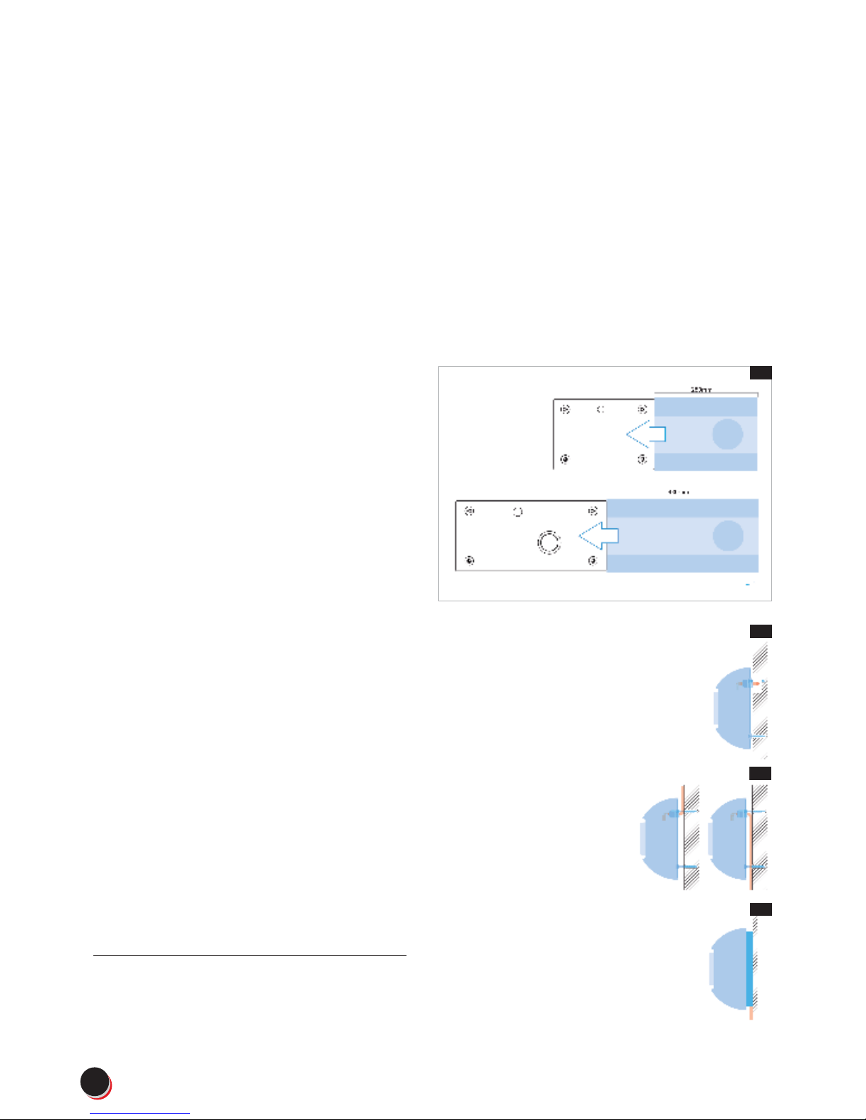
Mounting back plate to the wall
– Draw marks for drilling - for 3,7kW, 7,4kW chargers
use scheme from fi g.11, - for 11kW and 22kW
chargers from fi g.12.
– Relase cable gland fi g.10 and thread cable. Tighten
gland.
– Mount back plate on the wall, use proper screws.
fig. 10
fig. 11
fig. 12
9
www.smartev.co.uk | 01707 443 179
The installation, commissioning and maintenance
of the charging station may only be performed
by correctly trained, qualifi ed and authorized
electricians who are fully responsible for the
compliance with existing standards and installation
regulations.
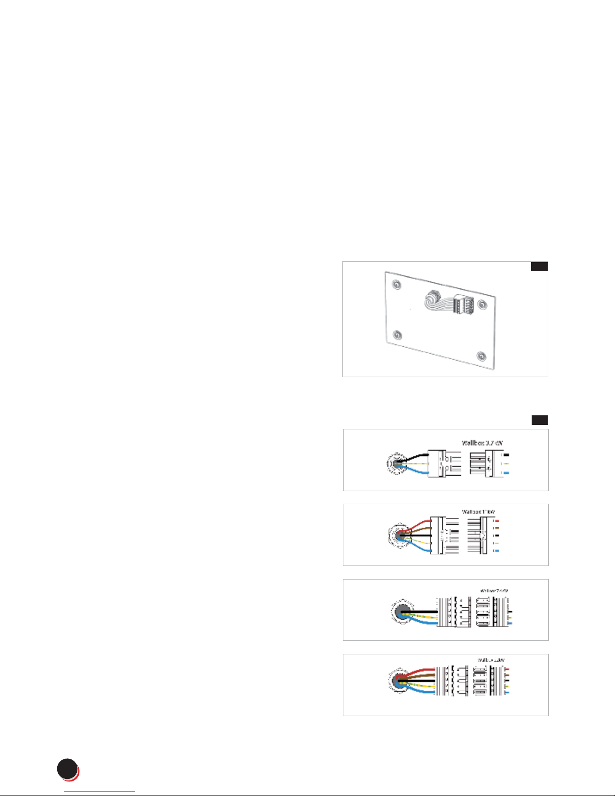
Connection to the power grid
– Connect wires from the cable to the
socket - fi g.13
– Use proper diagram for Scatalo 3,7kW, Scatalo
7,4kW, Scatalo 11kW or Scatalo 22kW fi g.14.
Terminal must be earthed. Ensure, that yellow-andgreen wire is connected to the working earhting
contact!
Ensure, that wires to power grid have proper
diameter. It must be minimum 2,5mm2 for 3,7kW
and 11kW installation (16A), and minimum 6mm2 for
7,4kW and 22kW installation (32A).
Installation Guidelines
fig. 13
fig. 14
10
www.smartev.co.uk | 01707 443 179

Closing the terminal
– Before slinding housing, make sure that a fuse
and RCD are turned on (working),
– Slide housing on back plate, fi g.15.
– Connect plug from housing to socket installed
on back plate fi g.16.
– Put a side cover fi g.17. and screw two security
screws to the case - fi g 18
First start
Turn the power on in the power grid supply.
On the screens you will see a welcoming message.
Terminal is ready to use.
fig. 15
fig. 16
fig. 17
fig. 18
11
www.smartev.co.uk | 01707 443 179

installation
SmartEv
One Woodside Lane
Bell Bar, Hertfordshire AL9 6DE
telephone 01707 443 179
www.SmartEv .co.uk
 Loading...