

SmartCompact
1D/2D Scanner
Quick Reference Guide
SmarTerminal Computers, Inc.
Ver 1, Nov 2006
Page 1 11/30/2006

Disclaimer
SmarTerminal and SmartCompact are registered trademarks of
Sammi Information Systems Co., Ltd.
All other brand names, product names, or trademarks belong to their respective
holders.
Head Quarters
Sammi Information Systems Co.,Ltd.
103-15, Galwor –dong, Yongsan-Gu, Seoul, Korea
Tel. 82 -2-790-5508 / Fax. 82-2-790-5509
Email. sales@sammicomputer.co.kr
Web. www.sammicomputer.co.kr
Us Office
SmartTerminal Computers, Inc.
15605 Carmenita Road Suit 209,
Santa Fe Springs, CA 90670
Tel. 1-562-921-5689 Fax. 1-562-921-5674
Email. sales@smarterminal.com
Web. www.smarterminal.com
Page 2 11/30/2006

Table of Contents
Introduction.............................................................................................................................. .5
Chapter 1 Get to know more about SmartCompact..................................................................6
1.1 Make sure you have everything............................................................... .....................6
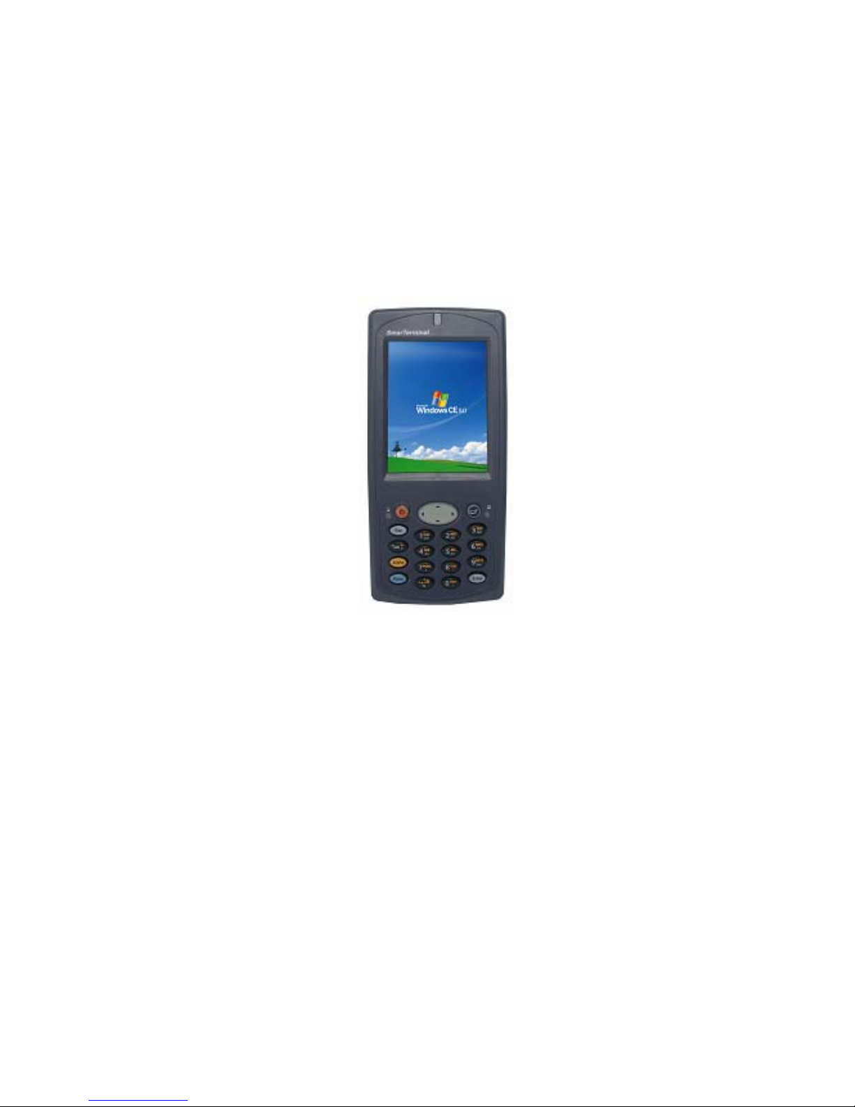
1.2 Appearance...................................................................................................................7
1.2.1 Front side..............................................................................................................7
1.2.2 Rear side............................................................... ................................................8
1.2.3 Top side ................................................................................................................9
1.2.4 Bottom side...........................................................................................................9
1.2.5 Left side..............................................................................................................10
1.2.6 Right side............................................................................................................10
Chapter 2 Hot Keys ............................................................... ..................................................11
2.1 Front panel with keys..................................................................................................11
2.2 Front panel keys description ......................................................................................11
2.3 Rear panel with keys...................................................................................................13
2.4 Rear panel keys description.......................................................................................13
Chapter 3 Power settings and connections............................................................................14
3.1 Power management....................................................................................................14
3.2 Install batteries in SmartCompact ..............................................................................14
3.3 Battery charging using power adapter.......................................................................14
3.4 Backup Battery on/off switch .....................................................................................14
3.5 Power settings on WIN CE..........................................................................................14
3.6 Turn on SmartCompact...............................................................................................16
3.7 Turn off SmartCompact...............................................................................................16
Chapter 4 Operation modes....................................................................................................17
4.1 Normal mode...............................................................................................................17
4.2 Suspend mode............................................................................................................17
Chapter 5 Resetting SmartCompact .......................................................................................18
5.1 Warm Reset.................................................................................................................18
5.2 Cold Reset............................................................... ....................................................18
5.3 Difference between cold and warm reset ............................................................... ....19
Chapter 6 Configuring SmartCompact....................................................................................21
6.1 Main Display screen description............................................................... .................21
6.2 Calibrating the touch screen ......................................................................................22
6.3 Setting up WLAN card ................................................................................................23
6.4 Setting up GPRS/GPS/CDMA/GSM Compact Flash card............................................24
6.5 Vo lume / sound control...............................................................................................27
6.6 Date/Time settings......................................................................................................29
Chapter 7. Applications and operations............................................................... ..................30
Page 3 11/30/2006

7.1 Scanning Barcode (1D/2D CCD type scanner ) ..........................................................30
7.2 1D/2D Scanner configuration settings ........................................................................31
7.3 Demonstration program for 1D / 2D Scanner.............................................................35
7.4 Blueman application program ............................................................... .....................38
7.4.1 Bluetooth application status...................................................................................38
7.4.2 Bluetooth Manager .................................................................................................39
7.4.3 Bluetooth settings ..................................................................................................54
7.5 Operating System upgrade manual............................................................... .............57
Chapter 8. Accessories and peripheral devices.....................................................................63
8.1 Using Stylus pen.........................................................................................................63
8.2 Using Compact flash (CF) slot....................................................................................63
8.3 Using SD (secure digital) peripherals.........................................................................63
8.4 Using CDMA (Code Division Multiple Access) module (Optional) .............................63
8.5 Using IrDA port (Infra Red Data Association).............................................................64
8.6 Using MSR printer (Magnetic Stripe Reader / Thermal Printer Module).....................64
Chapter 9. PC Interface...........................................................................................................65
9.1 Ms ActiveSync Installation............................................................... ...........................65
9.2 USB / Serial / IrDA ActiveSync............................................................... .....................67
9.3 Blueman ActiveSync...................................................................................................73
Appendix A.............................................................................................................................. 76
SmartCompact Specification Highlights.................................................................................76
Appendix B.............................................................................................................................. 79
Version Table...........................................................................................................................79
Page 4 11/30/2006

Introduction
This quick refe r enc e g ui de al lo ws yo u t o use al l the a dv an ced f eat ur es of S ma rt Com pact effe ct iv el y.
Please go through it once before using SmartCompact handheld terminal.
Page 5 11/30/2006

Chapter 1 Get to know more about SmartCompact
1.1 Make sure you have everything
9 SmartCompact main unit
9 Stylus Pen
9 Standard battery pack (
9 Power adapter
9 Power cord
9 Synchronization cable (USB cable)
9 Backup battery 110mA Lithium-ion (Embedded)
Optional accessories
9 Docking station (Desktop and vehicle)
9 CF card cover
9 Protective carrying case
9 MSR printer and cradle
9 RFID reader (Under development)
9 Synchronization cable (Serial)
9 Bluetooth printer with power adapter
9 3000mAh Lithium-ion
2000 mAH Li-ion)
Page 6 11/30/2006
1.2 Appearance
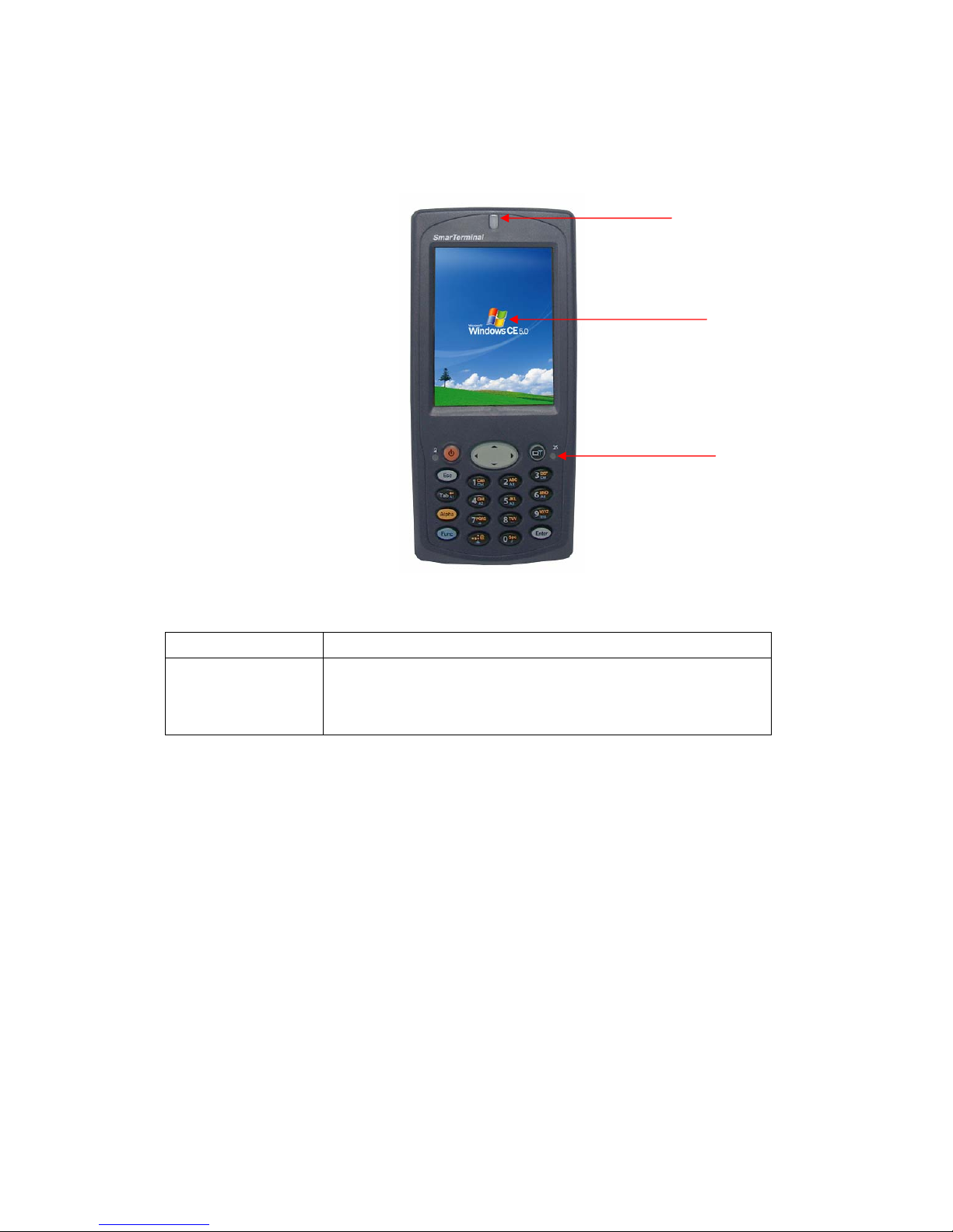
1.2.1 Front side
Scanner LED indicator
LCD Touch screen
Wireless LAN LED
Features and description
Features Function / Description
LCD touch screen
display
It shows the running application and desktop,
Stylus can be used to select the application and inputting data on
touch screen
Page 7 11/30/2006

Stylus pen
Internal speaker
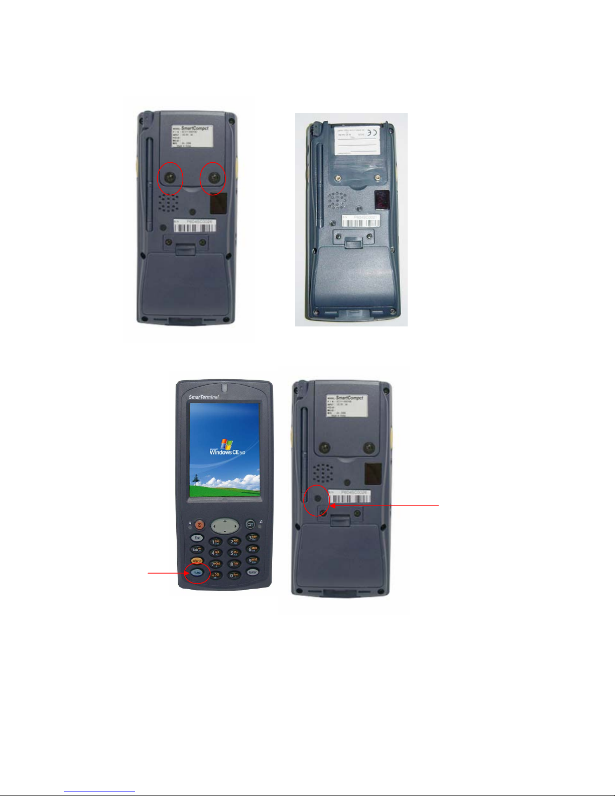
1.2.2 Rear side
Product label
IrDA port
Battery lock switch
Main battery
Rear panel features
Name Function
Stylus pen To use for touch screen
Internal speaker To output audio signals
Hand strap To hold SmartCompact unit
Main Battery To give Dc power to SmartCompact
Battery lock switch To lock/unlock battery pack
Backup battery on/off switch To turn backup battery on/off
Detachable hand strap end To detach hand strap easily for battery change
IrDA port To communicate with other devices usi ng in f r a red light
Product label To display model name and serial number
Page 8 11/30/2006

1.2.3 Top side
Slot cover
CF slot
1D Scanner window
Features and description
Features Function / Description
1D Scanner window While scanning the scanner beam is emitted and absorbed
through this window
Slot cover To protect the slot from dust
CF slot To host CF peripherals
1.2.4 Bottom side
Features and description
Features Function / Description
DC input jack For DC power adapter connection to charge the batteries
I/O port To connect to other devices using synchronization cable
I/O port DC I/p Jack
Page 9 11/30/2006

1.2.5 Left side
Left Scan Key SD slot with cover
Features and description
Features Function / Description
Left Scan key To scan the barcode user should press this key also known
was hardware scan key.
SD slot To host SD peripherals
1.2.6 Right side
Audio I/O port
Features and description
Features Function / Description
Right Scan key To scan the barcode user should press this key also known
was hardware scan key.
Audio I/O port To connect headset with microphone for audio signals in / out
Page 10 11/30/2006
Chapter 2 Hot Keys
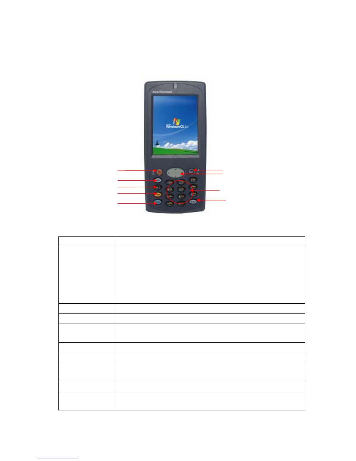
2.1 Front panel with keys
Power button
Esc Key
Tab Key
Alpha Key
Function Key
2.2 Front panel keys description
Key name Functions description
Navigation keys Default -- To move the cursor left, right, up and down
Power key (Orange) To turn SmartCompact (sleep / awake) and LCD backlight on/off
ESC key Functions same as “Esc” key on keyboard in windows mode.
TAB key Functions same as “Tab” key on keyboard in windows mode
Alpha key (Yellow) To switch to alphabet mode
Function key (Blue) Other keys in combi nation with “Func” key hav e secondary functions
Enter key Functions same as “Enter” key on keyboard in windows mode.
Alpha-Numeric keys To print various characters (0 – 9, a – z etc) in editor window
Home key To clear desktop
In Function mode
<up> To increase intensity of backlight
<down> To reduce intensity of backlight
<right> To increase speaker sound
<left> To decrease speaker sound
In function mode used to open application 1 or defined application
In function mode works as stylus calibration.
In function mode to turn wireless on/off.
Home key
Navigation key
Alpha-Numeric keys
Enter key
Page 11 11/30/2006

Alpha-numeric Keys functions in different modes
Key In numeric mode In function mode In alpha mode
<1> Prints number 1 on editor screen Functions as “Ctrl” key on
keyboard
<2> Prints number 2 on editor screen Functions as “Alt” key on
keyboard
To switch to Caps lock
mode
To print a/ b/c on
editor screen
<3> Prints number 3 on editor screen Functions as “Del“ key on
keyboard
To print d/e/f on editor
screen
<4> Prints number 4 on editor screen To open application 2 or
defined application
To print g/h/i on editor
screen
<5> Prints number 5 on editor screen To open application 3 or
defined application
To print j/k/l on editor
screen
<6> Prints number 6 on editor screen To open application 4 or
defined application
<7> Prints number 7 on editor screen Functions as “+” key on
keyboard
To print m/n/o on
editor screen
To print p/q/r/s on
editor screen
<8> Prints number 8 on editor screen Functions as “-“ key on
keyboard
To print t/u/v on editor
screen
<9> Prints number 9 on editor screen Functions as “Insert“ key on
keyboard
To print w/x/y/z on
editor screen
<0> Prints number 0 on editor screen Functions as “/“ key on
keyboard
To print blank space
on editor screen
<.> Prints number decimal/period on
editor screen
Functions as “*“ key on
keyboard
To print ,/:/@ on editor
screen
LED colors and description
Name On state
Battery charging LED (Left)
Blinking blue – Low battery (below 10%)
Page 12 11/30/2006

Wireless LAN indicator LED (Right)
Scanner LED (Top)
2.3 Rear panel with keys
Pistol key
Green – Fully charged
Red – While charging
Blinking green - Wireless LAN on
Red - Scanner result (error)
Green - Scanner result (success)
Reset key
2.4 Rear panel keys description
Name Function
Reset key To perform warm and cold reset
Pistol key For bar code reading when pistol trigger is pressed
Page 13 11/30/2006

Chapter 3 Power settings and connections
3.1 Power management
SmartCompact works on DC power.
A standard lithium ion battery pack (3.7V, 2000 mAH) is provided for Dc power input to
SmartCompact. Charging time is 5 hours with 10 operation and 100 standby hours.
Battery low (below 10%) condition is indicated with Blue power LED.
In order to support SmartCompact in low battery state, there is an inbuilt 110 mAH rechargeable
backup battery provided, it has backup time of 2.7 hours without main battery (in sleep mode).
For charging both main and backup batteries an AC adapter 100-240 V 50/60 Hz and 5 V/ 3A DC
output is provided with power cord.
Note: Never use SmartCompact unit without main battery.
3.2 Install batteries in SmartCompact
Detach the hand strap end on rear side of SmartCompact. Unlock the Battery lock switch.
Slid the battery latch upwards and insert the battery pack given with the correct polarity.
Note: Only use the batteries which are provided for SmartCompact units.
3.3 Battery charging using power adapter
Connect power cord from AC power supply to AC adapter/charger.
Connect Ac adapter to SmartCompact through DC input jack present on bottom si de.
While charging power LED will be red, after fully charged it will be green.
Backup battery also gets charged during this time.
Charging t i me is 5 hours.
3.4 Backup Battery on/off switch
Backup battery on/off switch is provided to turn backup battery on/off. When the SmartCompact
unit is dispatched from the factory, the switch is turned off for backup battery power saving.
To turn the switch on/off use stylus pen pointed top.
On position – Up
Off position – down
3.5 Power settings on WIN CE
To check the battery status
Start > Settings > Control panel > Power > Power properties > battery > power (main battery /
backup battery)
It shows the charged status of both main and back batteries.
Page 14 11/30/2006
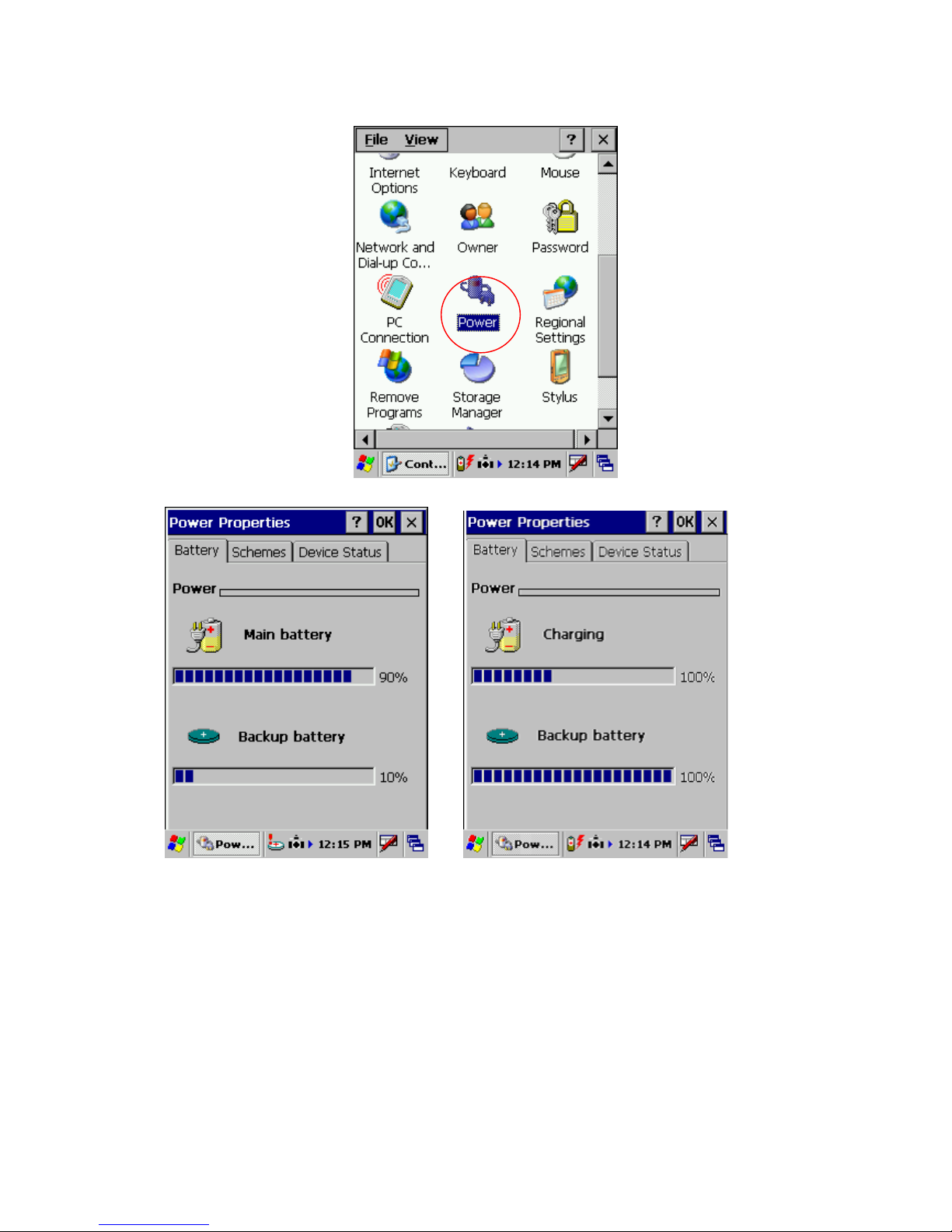
Awake mode while charging
Page 15 11/30/2006
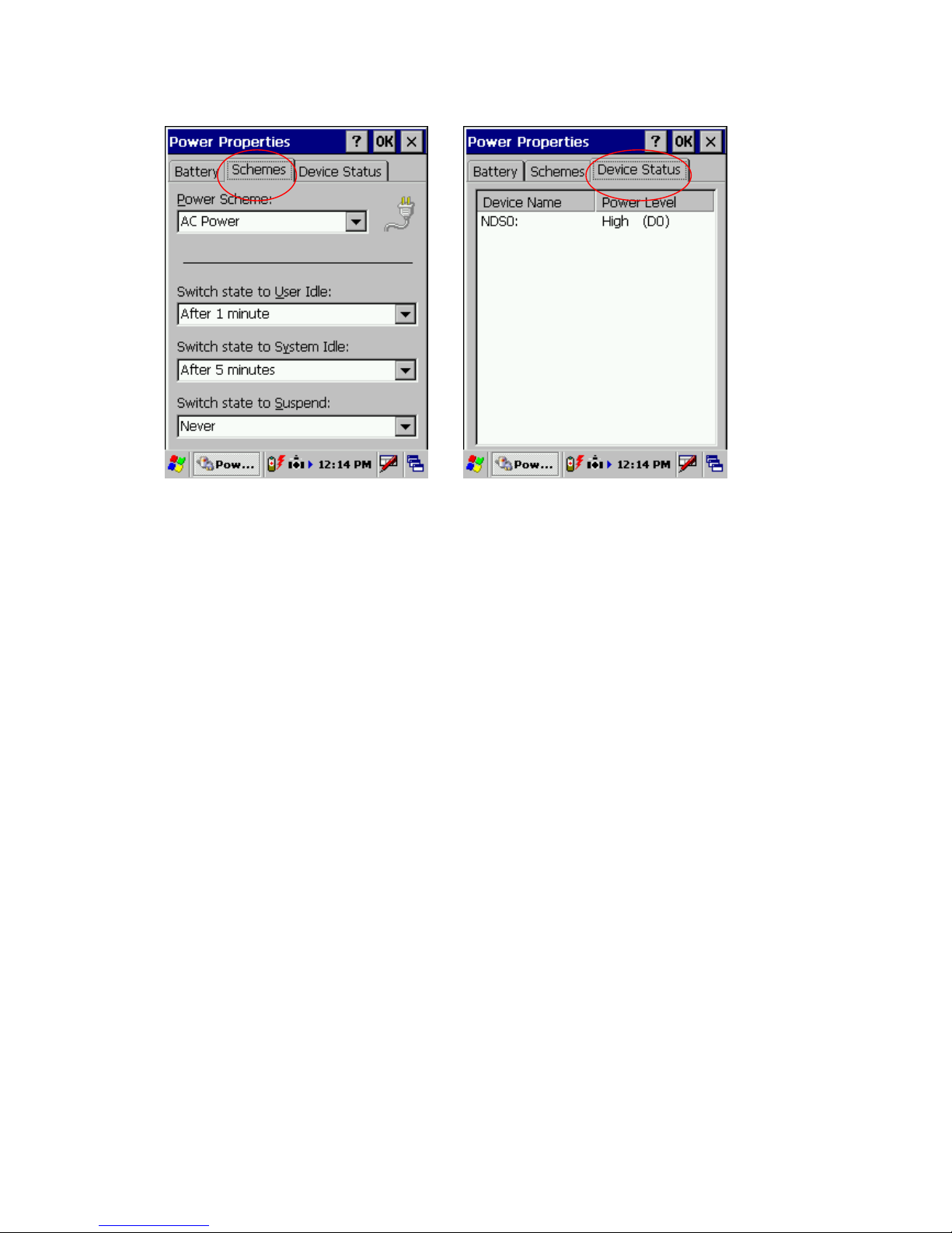
Power schemes Device status
3.6 Turn on SmartCompact
Check the backup battery switch position, to turn on SmartCompact unit it has to be up position.
Use stylus pen to turn it on.
Connect the main battery to SmartCompact main unit. Make sure that battery is fully charged for 5
hours, before it is used first time.
3.7 Turn off SmartCompact
To power off SmartCompact, hold the power key for 3 seconds, which will put the unit in sleep
mode. LCD backlight can be turned on/off by one touch on/off of the power key.
Page 16 11/30/2006
Chapter 4 Operation modes
4.1 Normal mode
In normal mode all functions will be available and SmartCompact will be active.
4.2 Suspend mode
In suspend mode SmartCompact will look, as if it is turned off.
SmartCompact can be put in suspend mode in following ways:
1 Holding down the power key for 3 seconds, when it is on.
2 If main battery fails.
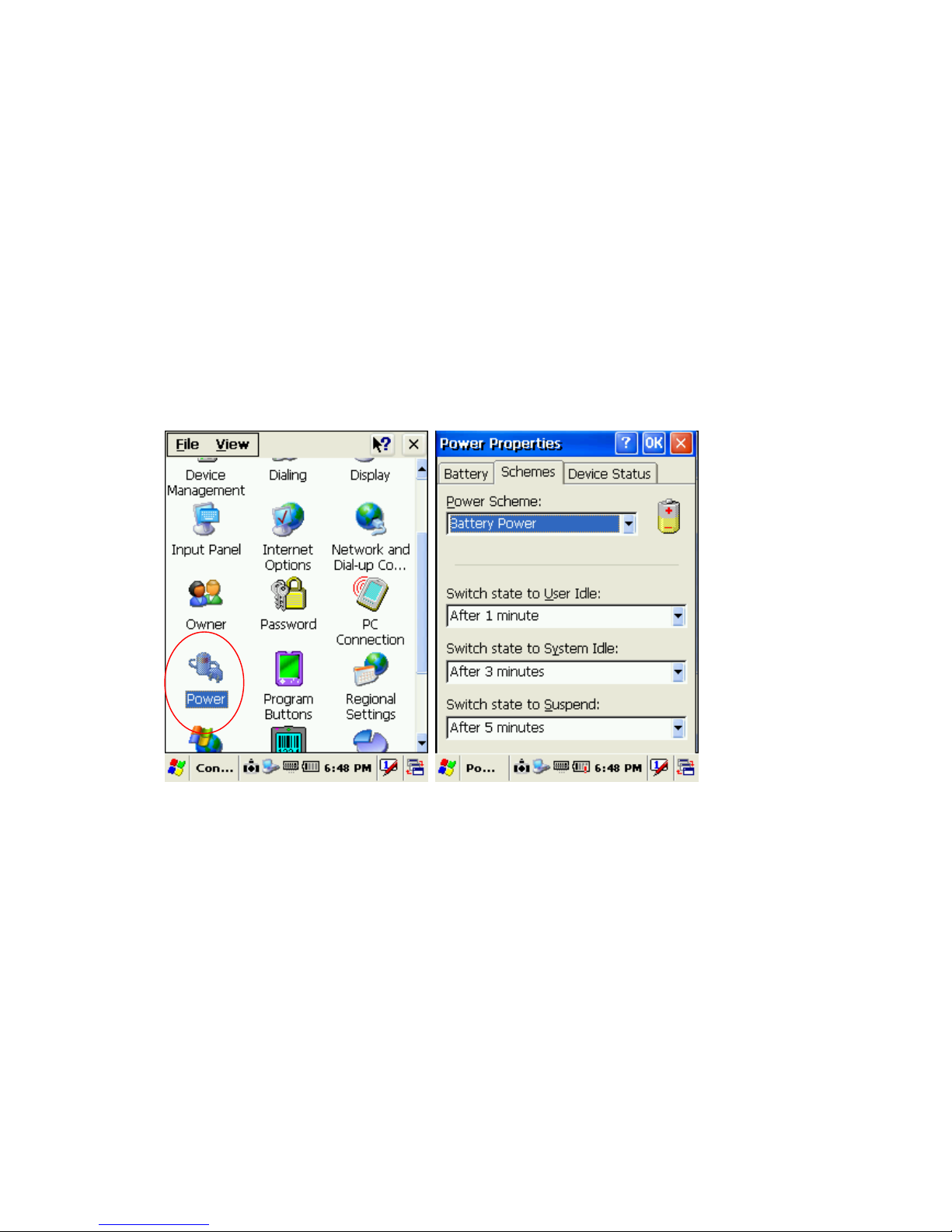
Note : If SmartCompact is not operated for specified period it can be switch to suspend
mode, this time can be set as follows
Start > settings > control panel > power properties > schemes > battery power
SmartCompact can be put back in active mode in following ways:
1 One press of power button, when SmartCompact unit is off.
2 By putting it in powered docking station.
3 By replacing the batteries with charged ones and press power button.
Page 17 11/30/2006

Chapter 5 Resetting SmartCompact
Resetting means closing all applications and refreshing RAM (Random Access memory)
This is done in two ways:
5.1 Warm Reset
If handheld hangs in between and stops responding, please perform warm reset.
In order to perform warm reset, press (one touch) software reset button till handheld starts
rebooting. Warm reset restarts the handheld by closing all the running programs. Always try warm
reset first, if handheld do not respond, then try cold reset. The data which is not saved will be
deleted and the saved data will remain in the appropriate directory.
5.2 Cold Reset
A cold reset clears the entire contents of RAM, including programs and data loaded in the Object
Store (system memory). But the data on the “Disk on chip” will remain as it is, so it is necessary to
store the important applications on “Disk on chip” before cold reset. The memory capacity of “Disk
on chip” is 60MByte.
The operating system is reloaded and any applications set up for automatic installation are
reinstalled. Cold reset is only recommended when all other procedures fail and SmartCompact
stops working.
Follow the instructions below for the cold reset
Method 1
Press and hold functio n key (front panel), and then press software reset key (rear panel)
simultaneously, till handheld starts rebooting.
Method 2
1 Release the lower clip of the hand strap.
2 Remove the battery pack.
3 Slid backup battery switch down and then again up to reset backup battery.
4 Reinstall the battery pack.
Following screen shots shows the cold reset functioning.
Ver 0.01
Ver 0.01
Page 18 11/30/2006
Checking CF Card
No CF card found

Ver 0.01
████████████
5.3 Difference between cold and warm reset
Topic Warm reset Cold reset
Reason for reset If application hangs If operating system locks up and
Refresh stat us It closes all applications
Preserves file system
Procedure to
reset
After state Splash screen will appear shortly
One touch of software reset button 1 Slide backup battery of/off switch down
Desktop will appear
warm reset does not work
It closes all applications
Refreshes RAM
Clears Files too
then again up.
2 Press Function key & software reset
key
After Splash screen booting image will
appear and then Desktop screen will be
shown.
Custom setting will remain persistent
Page 19 11/30/2006

Priority Always try warm reset first Only if warm reset fails then try cold
reset
Page 20 11/30/2006
Chapter 6 Configuring SmartCompact
6.1 Main Display screen description
Following is the display scr een picture
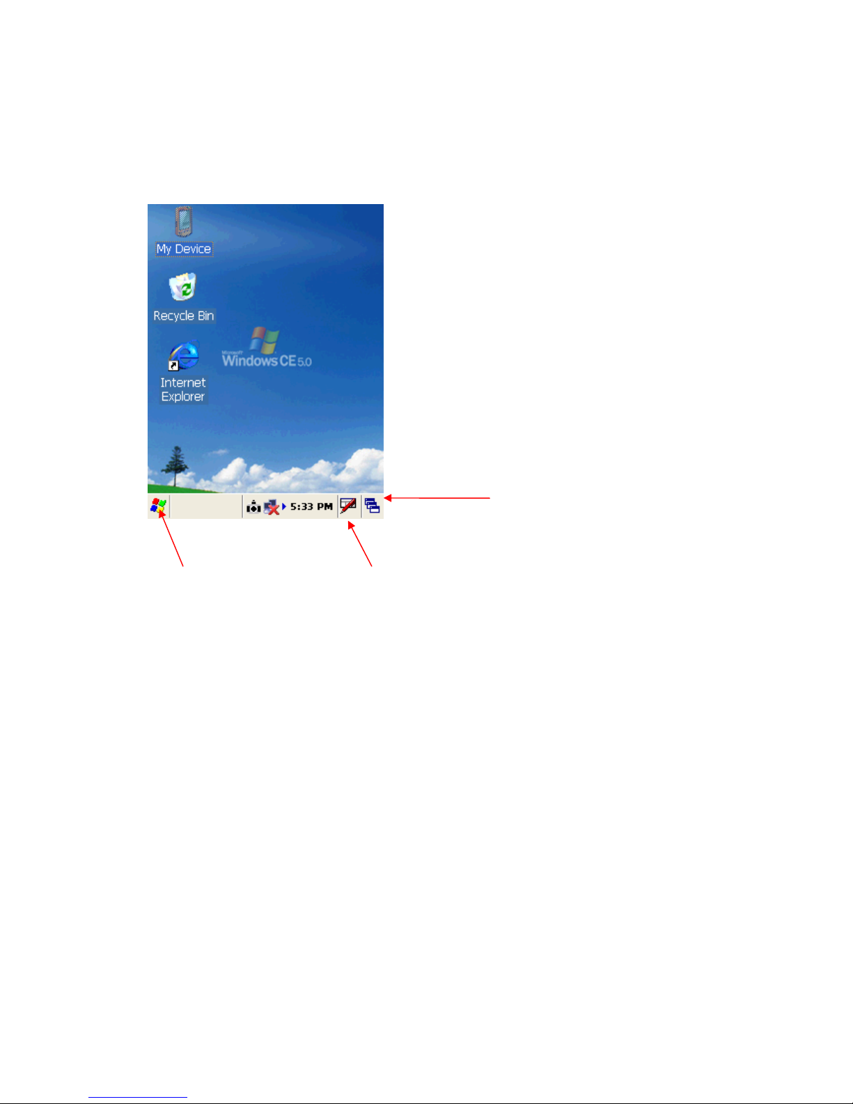
Task bar
Start button Keyboard icon
It has the following
1 Task bar
2 Start button
1 Task bar: The task bar at the bottom of the screen displays the start menu icon, icons for the
active programs, the current time and system icons for utilities loaded in memory.
It has keyboard icon, which opens and hides the soft input panel (SIP).
It has a button which shows present power status of SmartCompact i.e. either AC (power cord)
while charging, backup battery in low power conditions.
Task bar allows user to open and close the programs or utilities.
2 Start button:
Start button is at the left corner in the task bar which allows opening start menu.
Start menu has the following options
Programs > shows all the installed progra m list as well as user can ru n the programs from submenus
Favorites > User can set the internet favorites and the necessary programs
Page 21 11/30/2006

Documents > list of latest open documents
Settings > Control Panel
Network and Dial-up connections
Taskbar and start Menu
Help > Win CE help manual
Run command > To run programs directly
Soft Input panel (SIP)
The keyboard button allows user to open or close the onscreen keyboard. The keys of a keyboard
can be used by tapping them using sty l us pe n.
6.2 Calibrating the touch screen
In order to use stylus pen on touch screen it is necessary to calibrate the screen first
It can be done in following ways
Start > settings > control panel > stylus icon > Double tap / calibration
Double tap – Use the grid to set the double tap sensitivity for speed and physical distance between
the taps.
Calibrate - Hit the recalibrate button and touch the points shown on the screen till it says calibration
over. There is one more wa y to calibrate , press Function + Enter key.
Page 22 11/30/2006

6.3 Setting up WLAN card
In order to set WLAN settings
1 Open wireless settings screen using Function + home key, same key combination can be used
again to exit the wireless LAN.
2 Select the network which need to be accessed and tap the connect button.
3 To add a new network, double tab on Add new and select the network from the list.
4 confirm it using <Ok> or press <Enter> key on keyboard.
To change the settings of wireless LAN
Start > Settings > Network and Dial-up Connections, Right mouse click and select properties on
Wireless network
Page 23 11/30/2006

For IP address
Obtain an IP address via DHTP (Dynamic host c onfiguration protocol) > to get autom atic IP
address, if this fails
Specify an IP address > Enter IP address and Server address and select <OK>, i t connects to the
network. User can use any browser to access internet.
6.4 Setting up GPRS/GPS/CDMA/GSM Compact Flash card
Before installing the GPRS card it is necessary to sign up for GPRS data service with local wireless
carrier. Also get a SIM card that plugs into the CF card before installing it in SmartCompact.
Generally common GPRS CF cards are using serial interface so it is not necessary to install any
extra driver since they can use already available PCMCIA driver.
Note: If need to use very unique type GPRS card, please install the driver provided by
manufacturer.
GPRS CF card can communicate immediately after plug in.
Follow the in structions given below for using GPRS CF card.
1) Select Start> Settings > Netw ork and Dial -up Connections >
Make New Connection
Page 24 11/30/2006

2) Click on Make new connection
Type name of the connection and select Dial-Up connection and select Next
3) Select Modem type from the list as GPRS_Modem and Select Next
Tap on Configure to change the Port setting and Call Options as follows
Enter Baud Rate – 115200
Extra settings -- +cpin="xxxx";+cgdcont = 1,"ip"," yyyy"
Page 25 11/30/2006
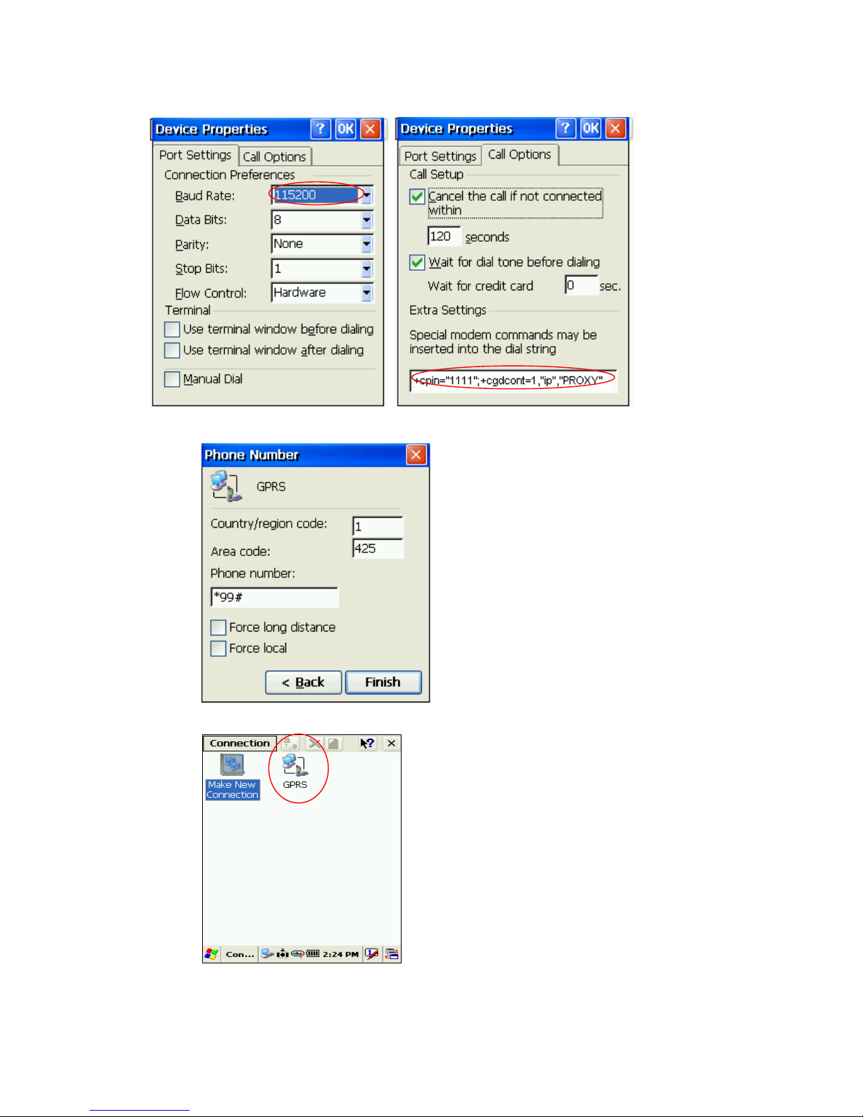
4) Enter Country and Area code, phone number and Click Finish
5) To connect to The GPRS network, double click on the new connection created
6) Enter User name, Password, Domain and click connect
Page 26 11/30/2006
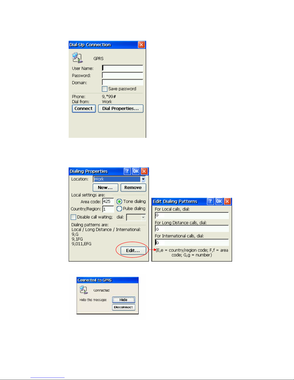
7) Change the Dialing properties as per the requirement
Click Edit to Change Dialing patterns e.g. Enter G for all options
8) After successful connections following screen will be displayed.
6.5 Volume / sound control
In Function mode Right and left navigation keys can be used to use to increase and decrease the
sound.
Page 27 11/30/2006

User can check the sound intensity with the background sound which is generated while increasing
and decreasing the volume through application
Start > settings > control Panel > Volume/sound
Volume - Adjust the volume as per the requirement using slider and check boxes.
Sound - Select sounds as per the requirement for each event.
Page 28 11/30/2006
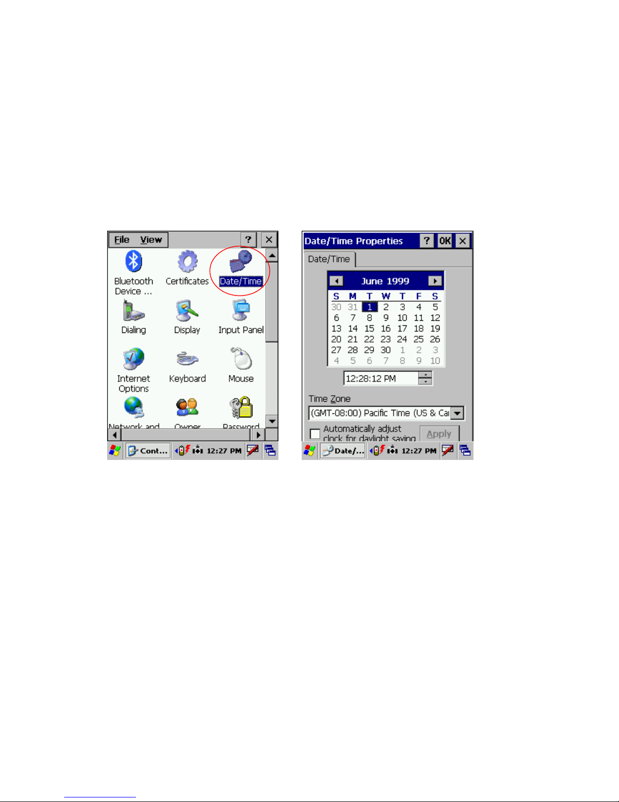
6.6 Date/Time settings
In order to set date and time do the following
Method 1
Start > settings > control panel > Date and time > Date and time properties dialog will show up.
Method 2
Double tap on the time on the task bar which will open up Date/time properties screen.
Change Date and time as per the requirement.
Page 29 11/30/2006

Chapter 7. Applications and operations
7.1 Scanning Barcode (1D/2D CCD type scanner )
CCD Charge coupled device technology scanner consists of a series of light-sensitive circuits that
capture the reflected light and register its intensity and color after it is reflected from a series of
mirrors. It utilizes the same technology that video cameras use.
Following procedure is used to read barcodes
1 Execute the application for bar code reading
Start > Programs > Scanning > ScanDemo application or use the icon on desktop
It runs in the background, use r can find out by the bar code icon in system tray
2 Aim the scanner window at the barcode
3 Press Left or right barcode scan button for 5 seconds
4 Aim the laser beam at the center of the barcode
5 check the scanni ng result eit her wi th beep sound or s ca n n er LE D indicator
Red > Error
Green > success
If there is an error, repeat the procedure till the barcode gets successfully read
Correct scanning method Wrong scanning method
Page 30 11/30/2006
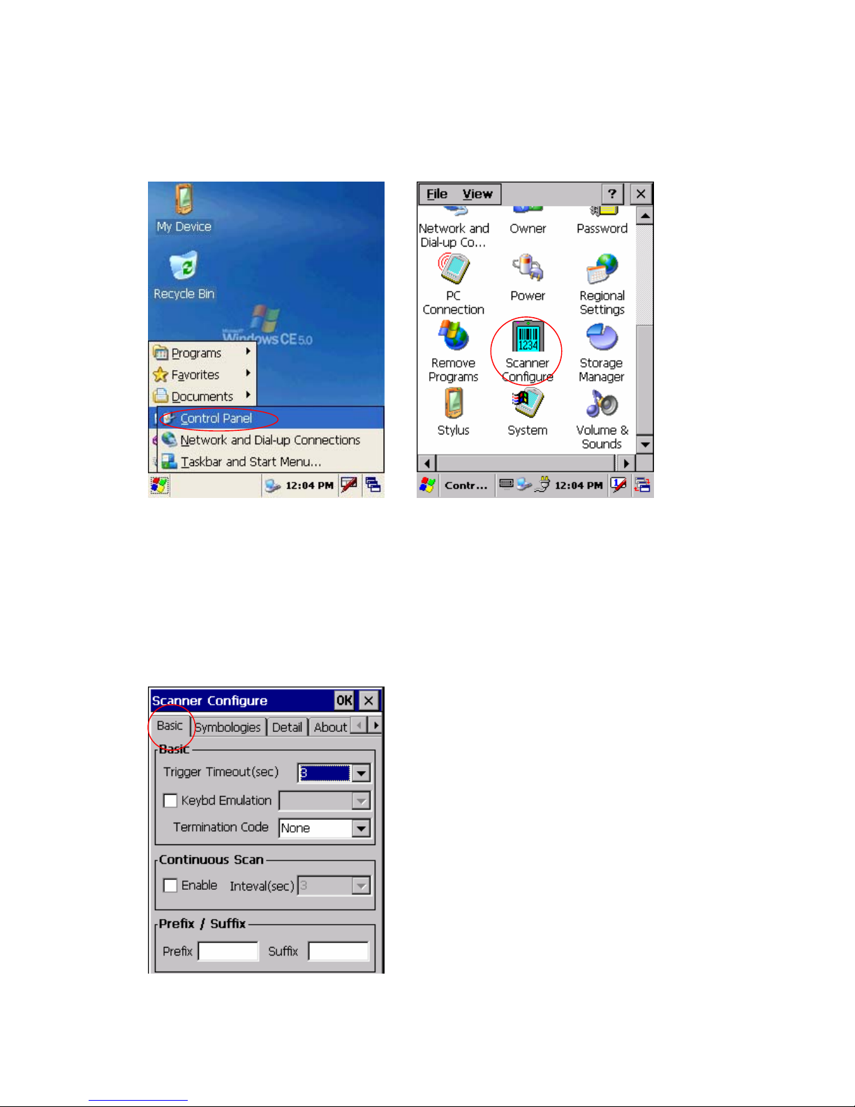
7.2 1D/2D Scanner configuration settings
Select Start > Programs > Control panel > Scanner configuration icon
Before you begin
This Application consists of the following 5 Tabs.
1. Basic -- Changes the default settings of Barcode scanner.
2. Symbologies -- Select the types of Symbologies.
3. Detail -- Changes barcode symbology parameter settings in SmartCompact.
4. Options -- Set the other functions of the scanner like Sound and Scan Key change.
5. About -- Shows the scanner configuration version and scanner firmware version.
Page 31 11/30/2006
Menu option Function
Trigger time out Scanning time in seconds, which is the waiting time to read a barcode
exactly .
Keyboard Emulation
(Disabled)
There will be no keyboard event after scanning barcode, scanned data
will be transferred directly to the user application
Type writing Shows encrypted barcode as alphanumeric form Keyboard Emulation
(Enabled)
Copy / paste copy /paste the scanned barcode in editor window
Terminator Add a automatic text after each bar code , it can be set as None, CRLF,
CR, LF, Space, Tab, STX -ETX
Continuous Scan
No continuous scanning
(Disabled)
Continuous Scan
Scan continuously the barcode with set time interval.
(Enabled)
Prefix Add code before each barcode e.g. when scanned value is 12345 and
prefix is ABC, It will be shown as ABC12345.
Suffix Add code after each bar code e.g. when scanned value is 12345 and
suffix is ABC, It has shown as 12345ABC.
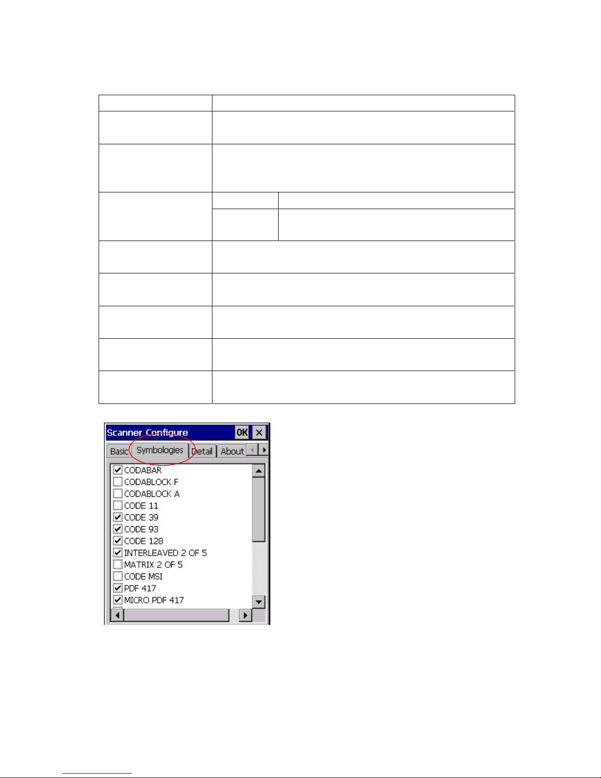
Check mark means select the barcode type for scanning, the unmarked barcodes will not be
scanned.
Page 32 11/30/2006
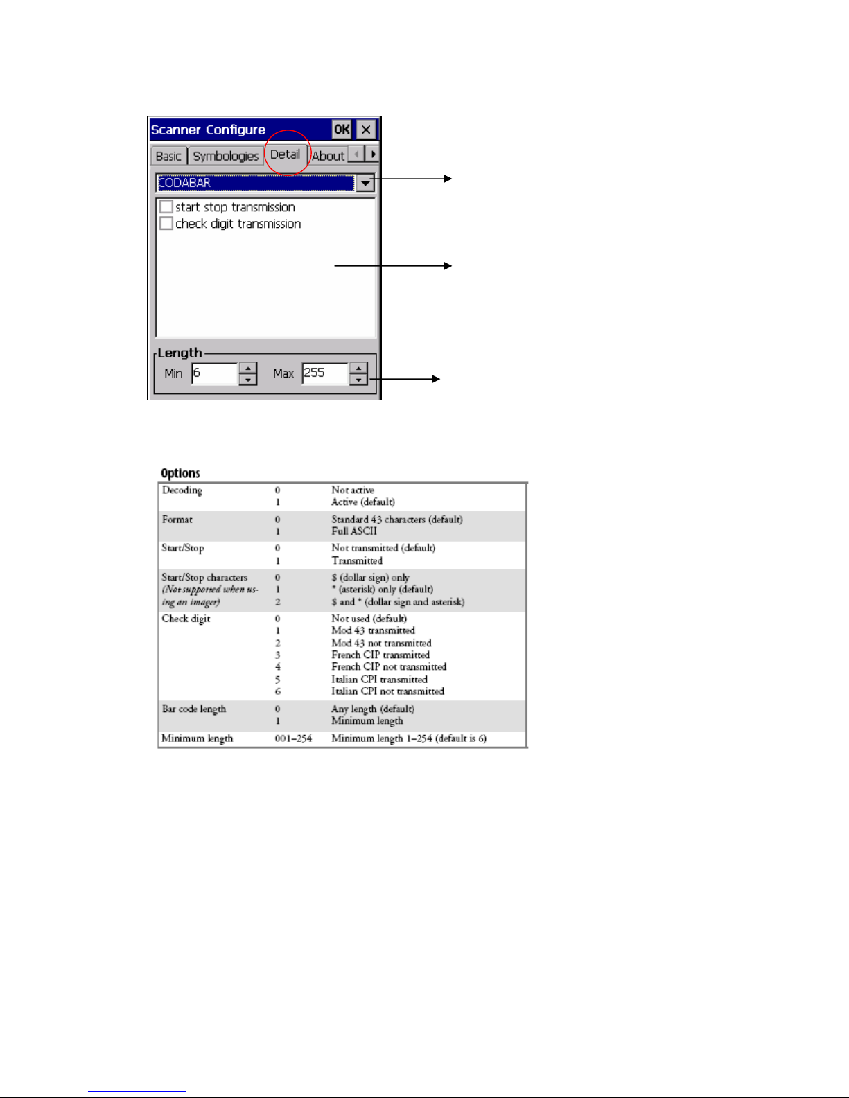
Barcode type
Detail setting values for
particular barcode type
Maximum and minimum
length of the barcode
belonging to this
barcode type
Page 33 11/30/2006
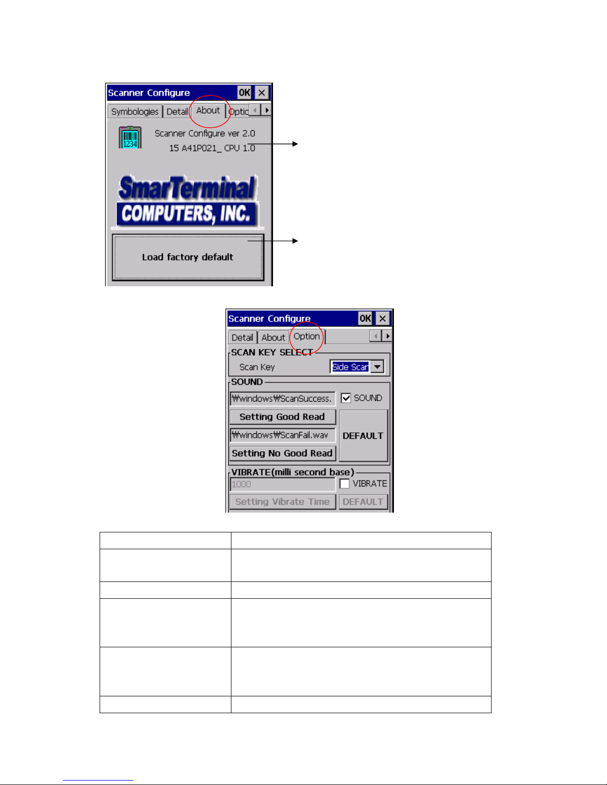
Scanner configuration version
Scanner firmware version
Restore back the factory scanner’s configurations
Menu Option Function
Scan key To define a scan trigger key (side scan key , HOME key,
Sound To activate beep sound
Setting Good Read Tap on this button allows to select the (*.wav) sound file for
Setting No Good Read Tap on this button allows to select the (*.wav) sound file for
Default Will restore back the default sound files for both operations
Page 34 11/30/2006
LEFT key, RIGHT key, UP key, DOWN k e y, ENTER key)
beep “On success of barcode scanning”
The selected file name will be displayed in the fill-in above
beep “On failure of barcode scanning”
The selected file name will be displayed in the fill-in above
success and failure
Vibrate Select to use vibrate mode on scanning (success/failure)
Vibrate (mille second base) Time interval for vibration
Setting Vibrate time To save the assigned time interval and test it
Default To res t ore bac k the default vibration settings
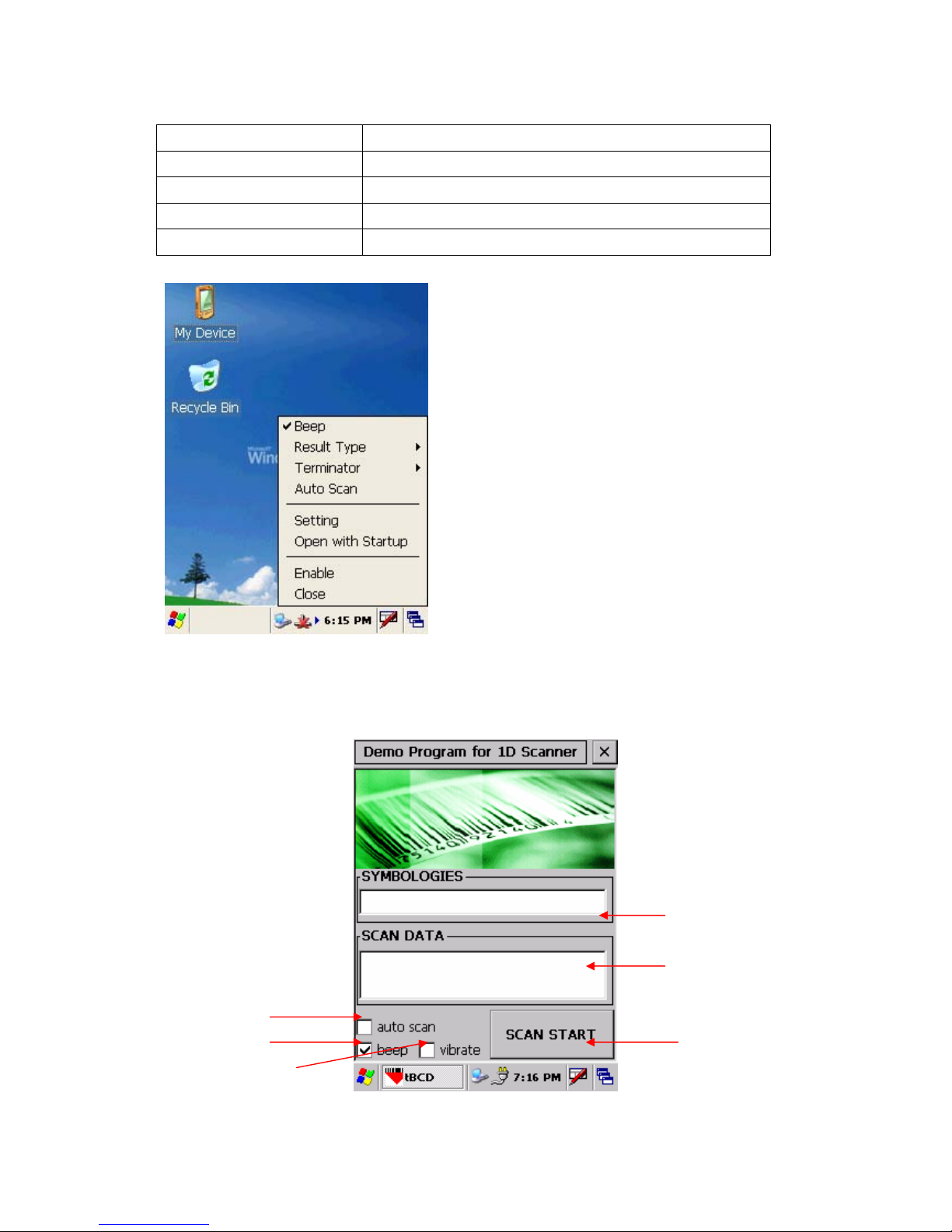
7.3 Demonstration program for 1D / 2D Scanner
To start the demonstration program Start > Programs > Scanner > ScanDemo
Startup screen for 1D Scanner
Select it for Auto-scan
Select it for beep
Select it for Vibration
Scan type will appear
Scan value will appear
To start scanning
Page 35 11/30/2006

Startup screen for 2D Scanner – Scanner waiting screen
Scan type will appear
Scan value will appear
To start scanning Select it for beep
Select it for Vibration
For Scanning bar code user can either press SCAN START button once or one of the hardware
buttons on the left/right side of the SmartCompact unit. The result will be same for both procedures.
After successful barcode
scanning the scan type and
value will be displayed in
respective fill-ins
On failure of barcode scanning
Scan fail and try again messages
will appear
For Beep select Beep checkbox, the specific beep sound can be selected through control panel
settings.
Page 36 11/30/2006

For Vibration on success or failure select vibrate checkbox.
For Auto scan select the auto scan check box. Unless deselected the auto-scan mode will be
activated whenever user starts the program.
In auto scan mode, once the < Scan start > button is pressed, the scanning beam will continuously
come till <Scan stop> button is pressed.
Copy data captured by QuickScanSet to wordpad
Start > Program > Click QuickScanSet Double click QuickScanSet in task bar and select
Copy and Paste
Page 37 11/30/2006

Start > Program > Run wordpad Scan start > Scanned barcode data will get copied to
wordpad
7.4 Blueman application program
Blueman supports Bluetooth 1/2 and Blueclass 2 (10 mW) specifications.
Note :
• Maximum only two services can be connected (SPP and FTP, ActiveSync and FTP)
• SPP and ActiveSync can not be connected simultaneously since they use the same
outbound port
• While both SPP and FTP are in use the service search might not be available.
• Whereas the part which is saved automatically in setting is shown in red and others are
saved by closing the setting form.
• The class of device of P DA which installs Blueman is applied to Handheld PDA in service
on.
7.4.1 Bluetooth application status
- There are 3 types of Bluetooth status; Off, On, Connection
- You can check the current status of Bluetooth in the tray icon as shown below
User interface Status
Bluetooth Radi o Off : Inactive
Gray color
Bluetooth Radio On : Active
Blue color
Bluetooth connection: In use
Green color
Page 38 11/30/2006
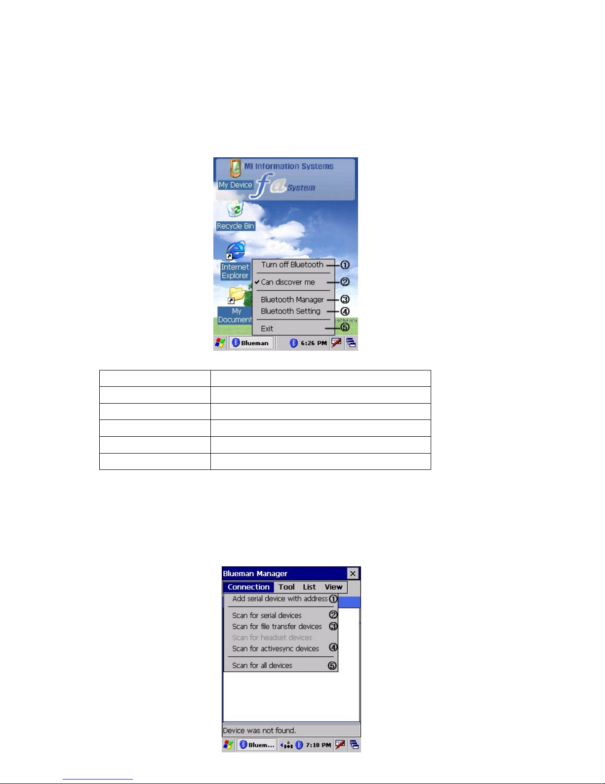
Blueman tray icon popup menu
By double clicking on Blueman tray icon user can get popup menu as shown in following
screenshot
Menu name Description
Turn off Bluetooth To activate / deactivate Bluetooth
Can discover me Allow other devices to access PDA using Bluetooth
Bluetooth manager To manage Bluetooth
Bluetooth setting To configure Bluetooth settings
Exit To exit Blueman application
7.4.2 Bluetooth Manager
Bluetooth manager is used to manage Bluetooth. It has four menus
Connection, tool, list and v iew
Connection : Allows PDA to access and connect to other devices which support the same services
e.g. serial, file transfer and AciveSync service.
Page 39 11/30/2006
Menu Function
1 Add serial device with address To add a shortcut to search and connect serial
device using its Bluetooth address
2 Scan for serial devices To search the device with the serial service.
3 Scan for file transfer devices To search the device with file transfer service
4 Scan for ActiveSync devices To search the device with ActiveSync service
5 Scan for all devices To find out all Bluetooth devices
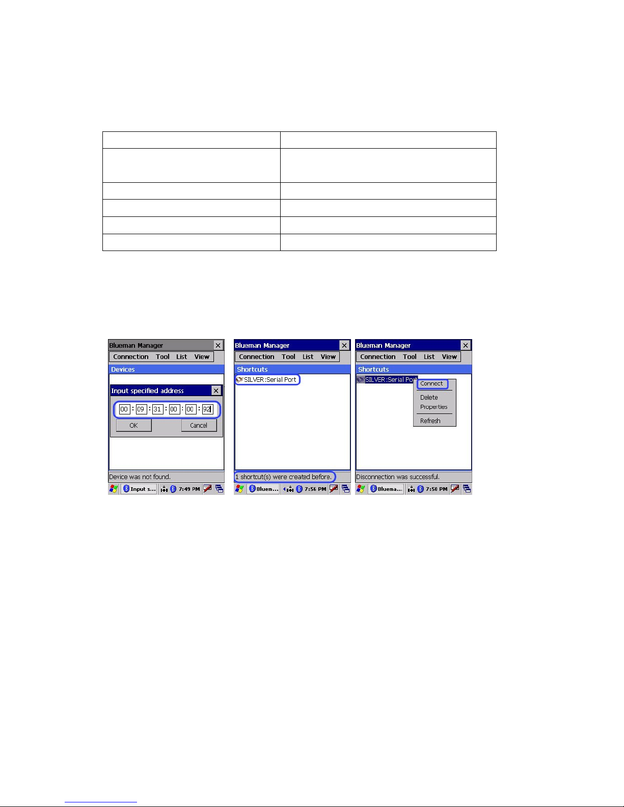
Add serial device with address
This section will enable PDA to search and connect the device with serial service using a specific
address. Follow the steps given to search the Bluetooth device:
Enter Specific address Shortcut icon will appear Double click on icon for popup menu
Select “Connect”, the serial service will start with the message “COM8 port was created for SPP
client”.
Double click same icon for the following popup menu.
Disconnect – To stop th e service
Delete – To d elete the ic on
Properties – To show properties of the service
Refresh – To refresh the current connection or setting information
Page 40 11/30/2006
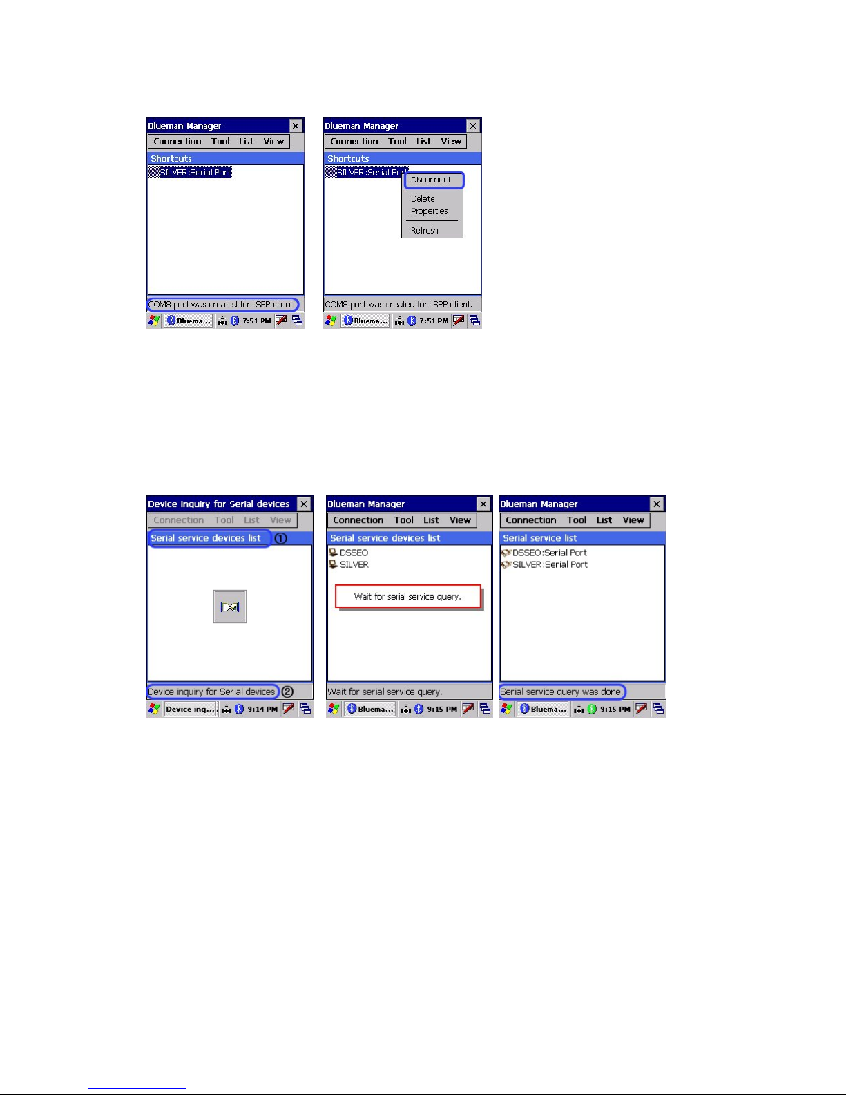
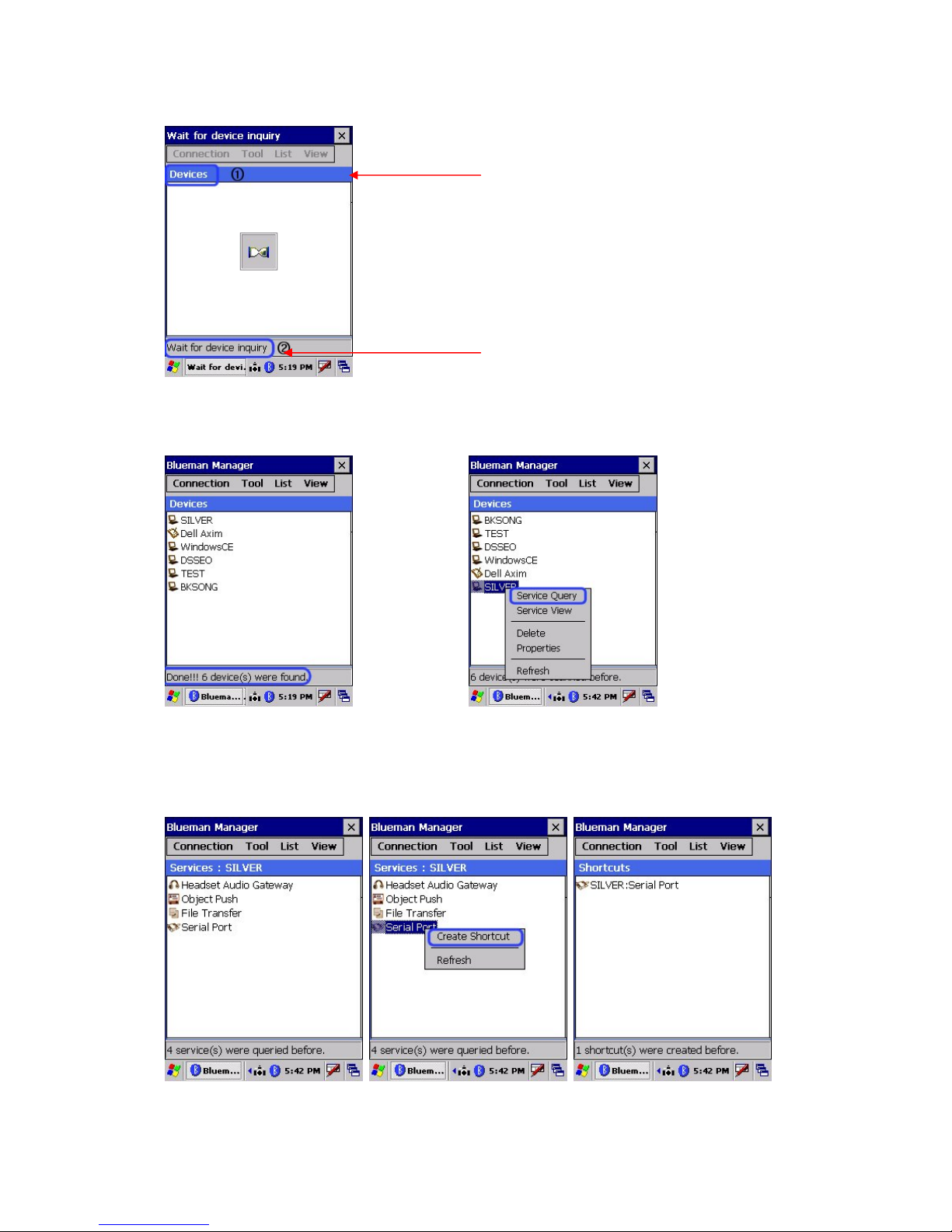
Scan for serial devices
This is used to create shortcut to find and connect all the devices with serial service.
When Bluetooth address is not known, Scan for serial devices option can be used to search
serial devices.
System will automatically Service query screen Query is finished and serial service
Search Bluetooth devices list is displayed as follows
with serial service.
Select specific service & Double click for popup menu
Select <Create shortcut> Select <Connect >
Page 41 11/30/2006

Select “Connect”, the serial service will start with the message “COM8 port was created for SPP
client”.
Double click same icon for the following popup menu.
Disconnect – To stop the service
Delete – To delete the icon
Properties – To show propertie s of the service
Refresh – To refresh the current connection or setting information
Scan for file transfer devi ces
Use this section to enable your unit to receive files from another Bluetooth device, or from any
Page 42 11/30/2006
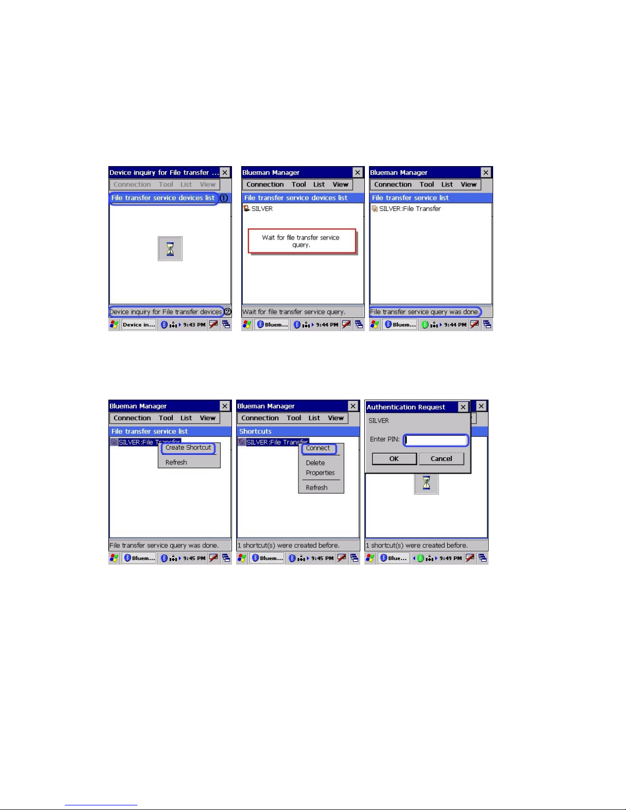
device that supports this function (FTP).
Search Bluetooth device: The system automatically searches for a list of Bluetooth devices in the
screen that will support a FTP service.
<Device searching screen> < Service query Screen > < List complete Screen >
Select device & click create Double click on device icon For security authentification
Shortcut to get popup menu, select Enter PIN of the device
Connect
Page 43 11/30/2006

To go to the upper folder (You cannot
go from default folder to the upper
folder to prohibit from deleting the
system folder.)
- To Make a new folder
- To Send or receive file
(You cannot download a folder)
- To delete a file
(You cannot delete a folder)
- Refresh
Large Icons : The icons in the current
screen are seen large
Small Icons : The icons in the current
screen are seen small
To send a file from remote device to local device
- Click the Loc al Machine tab, which is defined as the
default.
- Select the file and then click transfer icon. When the
message of “send to remote” pops up. Click “yes”.
Page 44 11/30/2006
Status message “Sending file to remote” is displayed
during file transfer.

When file transfer is done, you can see the message
of “sending file to remote was successful” on the
status bar, located at the bottom of the screen.
To send a file from Remote device to Local device
- Click the Remote Machine tab.
- Select the file and click “send to.. icon”. When the
message of “send to remote” pops up. Click “yes”.
- The message of “s endi ng f il e to loc al” is s hown in the
status bar of scr een.
Page 45 11/30/2006
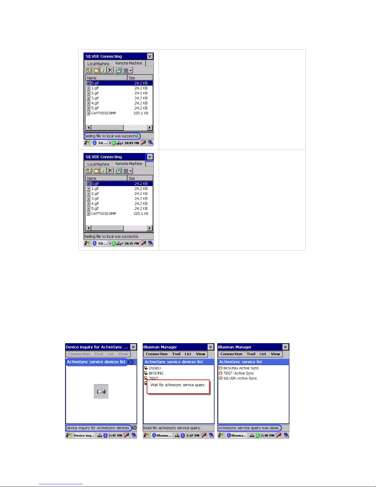
- When the file transfer is done, you can see the
message of “sending file to remote was successful” on
the status bar, located at the bottom of the screen.
To close FTP Program
- Tap the close icon(X) in t he top-right corner to exit
and disconnect the service connection.
< file transfer service Function>
** Regarding FTP Host function, enter the agreed pin number for both PDA and
other Bluetooth device to make a connection.
Scan for ActiveSync devices
- This section describes how to make a shortcut to search and connect all Bluetooth devices
with ActiveSync service.
Search Bluetooth devices which support ActiveSync service
<Device searching screen> < Service query Screen > < List complete Screen >
Page 46 11/30/2006

Select device & click create Double click on device icon Message after successful
Shortcut to get popup menu, select connection
Connect
To disconnect the service
Scan for all devices
This section describes to search and query all Bluetooth devices respective services. User can
make a connection if required.
All Bluetooth devices
When you select this function, you can search and list up all Bluetooth devices with the following
procedure.
To search Bluetooth devices
Page 47 11/30/2006
The service type to scan is shown in
the title bar
The status of blueman manager is
displayed in the status bar below.
List of devices which support Press and hold your stylus in the device
Bluetooth service icon for a pop-up menu, then select “Service Query”
Once the ser vice query is To create shortcut, hold stylus Use popup menu to connect
Complete, list of services on service icon to display popup and disconnect the service
which device supports will be menu and select Create shortcut
displayed as follows
Tool
Page 48 11/30/2006

This tab enables the device to set the paired status with other device or activate/deactivate the
Bluetooth radio.
To save the settings which
were used to connect to
other specific devices
To turn Bluetooth service
on and off alternatively
Setting for paired devices: Follow the steps below to add paired devices
Select Add to scan the Wait till the list is complete On specific device popup menu select
Device to be paired Add paired device to select the device
Enter the PIN
Enter the promised authenticated key in both your device and the relevant device to complete the
connection.
Page 49 11/30/2006
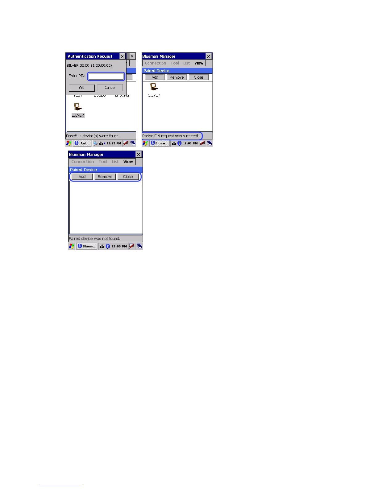
Add: To scan the device to connect
Remove: To remove the paired
device
Close: To exit
Page 50 11/30/2006

Double-click a device to see a pop-up menu containing a list of actions you can perform like
below.
c Add Paired Device : to make the device paired.
d Properties : to see the information on the device.
e Refresh : to renew the window(N/A)
d Properties : to see the information on
the device.
Turn on/off Bluetooth
This function allows the radio service of the device to turn on or off.
List
This tab enables user to check the scanned device / service, or shortcuts which have been
created earlier options.
Page 51 11/30/2006
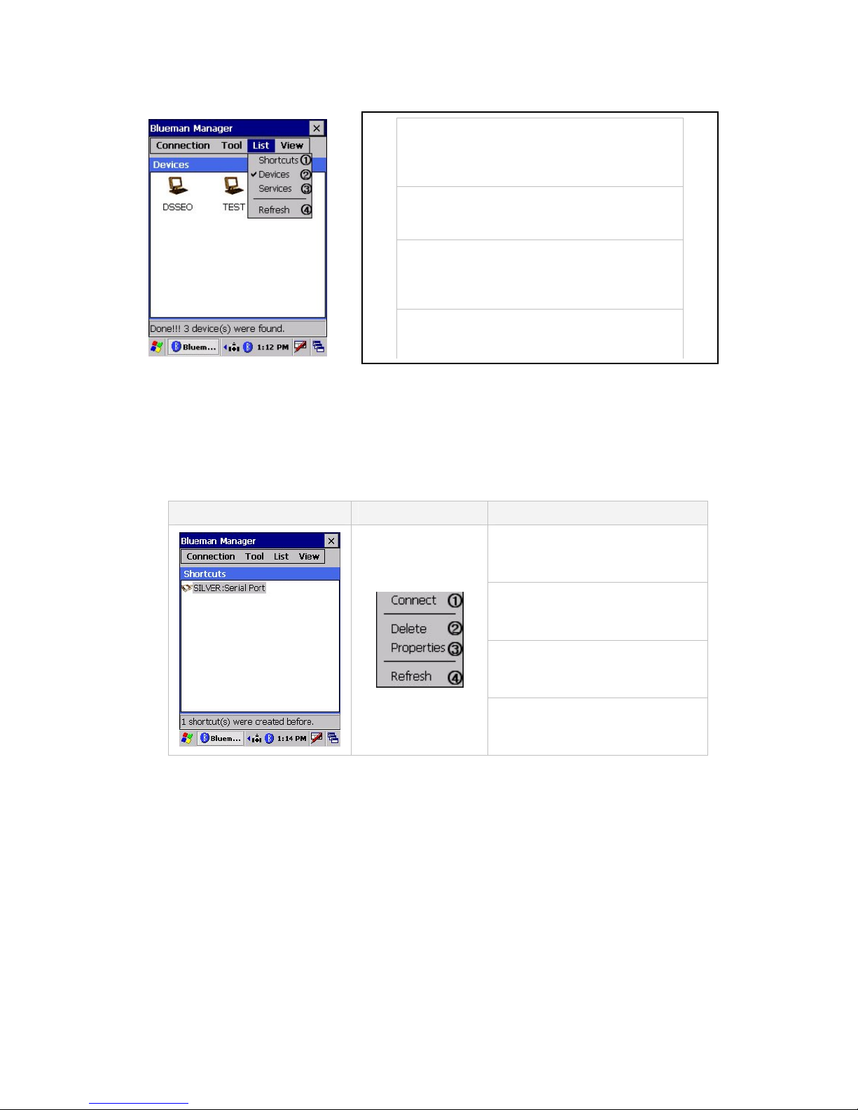
c Shortcuts: to list up the shortcuts to
connect to the device service, which have
been created in “Connection”
d Devices: to list up the devices which have
been scanne d in “Scan for a ll devices”
e Services: to show the device services
which the service query has been done in
“Scan for all devices”
f Refresh: to renew the current page.
Shortcuts
This function shows the shortcut list of device services, which has been created in.
<Connection>. This is available only after you create the shortcut in a connection tab. If not, the
message of “?“ will appear.
Screen Pop-up Menu Action & Description
c Connect : to connect to the
service
d Delete : to delete the shortcut
e Properties : to show the device
information
f Refresh : to renew the current
window
Page 52 11/30/2006

Devices
This function enables user to review the information on the device service or the other detailed
information. This is available only after you have searched the devices in a connection tab.
Screen Pop-up menu Action & Description
c Service Query: to scan the
service of the device.
d Service View: to show the
service , which was saved.
e Delete: to delete the device.
f Properties: to see the
information of the device.
gRefresh: to renew the device.
Services
This funct i on enables user t o v i e w t he de v ice servic e whi ch has a step of service que ry in “ S c a n for
all devices”
User can create a shortcut of scanned service.
Screen Pop-up menu Action & Description
c Create Shortcut : to make
a Shortcut
Page 53 11/30/2006
d Refresh: to scan the
device again.

View
- This tab enables user to control the shortcut display of either large icons or small icons.
Large Icons: The shortcut icons in the current page become large.
Small Icons: The shortcut icons in the current page become small.
7.4.3 Bluetooth settings
This has four submenus General, Accessibility, Services, and About
General
1) Bluetooth status
- To turn Bluetooth radio on / off
(This is same as on/off in a tray icon or Bluetooth manager)
2) Device Identification
A. Name: To change the device name
B. Address: To show the BT address of the device. The
device must be on.
3) Device Scan Length
- To control the device (or device name) scanning time.
Page 54 11/30/2006
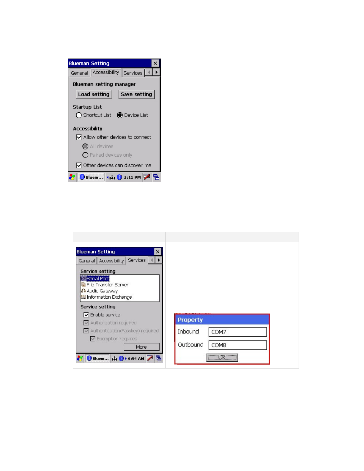
Accessibility
1) Blueman setting manager
A. Load setting: To load the saved blueman registration value.
B. Save setting: To save the current blueman registration value
2) Startup List
A. Shortcut List: To establish the shortcut list as a default screen
in opening the program.
B. Device Li st: To establish the device list as a default screen in
opening the program
3) Accessibility
A. Allow other devices to connect: To allow the service
query for your device from other devices
B. Other devices can disco ver me: If you don’t check this,
other devices cannot scan your device.
Services
This menu enables you to change the setting values of the Bluetooth service.
Screen Description
1) Serial Port
-To enable or disable SPP Service
(Both Authorization and Authentication are
inactivated because WinCE5.0 doesn’t support
them.)
<<More>> You can check the settings of SPP
Inbound &Out bo u n d P o rt he re. (unchange a b l e)
Page 55 11/30/2006

2) File Transfer Server
- In FTP service, all settings in File Transfer
Server are inactivated because it’s controlled by
OS itself.
<<More>>
(Default folder :My documents\File Transfer)
3) Audio Gateway
- This is supported in MS Stack. However, all
settings are inactivated because the service is
unavailabl e currently.
(Only possi ble to scan the service for other BT)
Page 56 11/30/2006
4) Information Exchange
- to switch files of PIM, calendar, and etc.
(Default folder: My documents\Default\Inbox)

About
User can view the latest software build version by accessing this tab. Tap ok(x) to exit this
information.
7.5 Operating System upgrade manual
Please follow the steps below to upgrade the operating system on SmartCompact.
1 Copy the OS file of “nkupd.bin" to CF card.
Page 57 11/30/2006
2 Remove CF cover from PAD by removing two screws on rear panel and insert CF card
3 Press Fn key + Reset button for cold reset
Software reset Key
Func key
4 PDA will automatically search for OS to update in CF Card or SD Card. If there's OS file to
update, move to (No.6)
Page 58 11/30/2006

Ver 0.01
5 If there's no OS file to update, move to (No.9)
Ver 0.01
Page 59 11/30/2006

6 Reads CF Card from OS File
Ver 0.01
7 Old version OS will be removed and updated to New OS
Ver 0.01
Page 60 11/30/2006

8 Remove CF card when update completed, press FN KEY + Reset for Cold reset
Ver 0.01
9 Image booting after cold reset
Page 61 11/30/2006
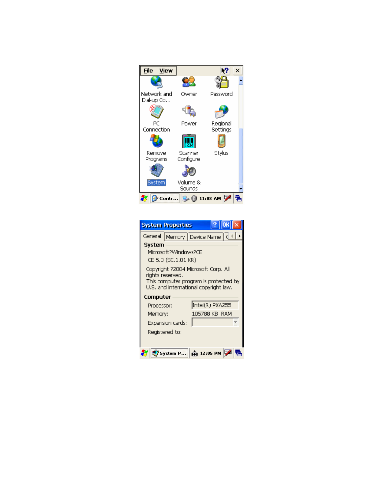
10 Check the OS version in Control Panel > System
11 double click System to check OS Version
Page 62 11/30/2006

Chapter 8. Accessories and peripheral devices
8.1 Using Stylus pen
The stylus on the PDA is same as mouse on a PC.
Usage of stylus
1 Navigate the touch screen display
2 Select characters in soft input panel
3 Select applications from the desktop or system tray
4 Select buttons, tabs, fields and text within ap plications and editors
8.2 Using Compact flash (CF) slot
Compact flash slot available on SmartCompact has possibility to insert CF peripherals (50 pin).
The digital platform supports 3.0 V type I/II cards but it can be upgraded to support 3.3 V CF
cards. After inserting the CF card it is possible to close the slot with CF close cover. The cover can
be changed by removing screws located at the top side of SmartCompact as shown in figure 1.2.3
top side using a small Phillips head screwdriver.
To install CF peripherals
• Before installation, in order to pull CF cards easily out of a CF card slot, a pull-out
sticker comes with the CF card package. If an equivalent sticker doesn't come with your
card, or your PDA doesn't have an eject button, stick pull-out sticker to pull CF cards e
asily.
• In case of closed covers user should remove screws and cover, insert CF cards, close cover
and fix the screws.
• There are different types of CF peripherals available in market which can be connected to
SmartCompact e.g. CF camera, CF CDMA, CF Bluetooth, CF memory card, GPRS CF card
etc.
• For installing drivers for CF peripherals please refer the installation manuals provided with the
equipments.
8.3 Using SD (secure digital) peripherals
On the left side of the SmartCompact SD slot is available for SD peripherals insertion.
For Installation open the cover by removing the screws on the left side of the unit.
Insert the SD card in the slot. System should automatically detect the SD peripheral.
To remove the SD card, press back the card and it will automatically come out.
8.4 Using CDMA (Code Division Multiple Access) module (Optional)
CDMA1-X1 (class B) can be used with SmartCompact through compact flash slot which is available
on rear side.
Page 63 11/30/2006

8.5 Using IrDA port (Infra Red Data Association)
SmartCompact is provided with standard IrDA 1.1 compliant SIR. It can communicate with another
device with IrDA port; the distance in which it can operate is 7.8” – 11.8”. Microsoft ActiveSync is
software which can be used for communication.
8.6 Using MSR printer (Magnetic Stripe Reader / Thermal Printer Module)
It is possible to connect MSR printer to SmartCompact through I/O port. For more details please
refer MSR printer user manual.
Page 64 11/30/2006

Chapter 9. PC Interface
9.1 Ms ActiveSync Installation
It is possible to connect SmartCompact to Host Pc using synchronization cable.
Attach one end of synchronization cable to Sync port which is on bottom side of SmartCompact
and USB end to host Pc. It is necessary to install Microsoft ActiveSync program.
Following is a procedure to install Ms ActiveSync program on PC.
Select “Next”
Select “I accept the terms in the license agreement” and then “Next”.
Input Username and Organization name and select “Next”.
Page 65 11/30/2006
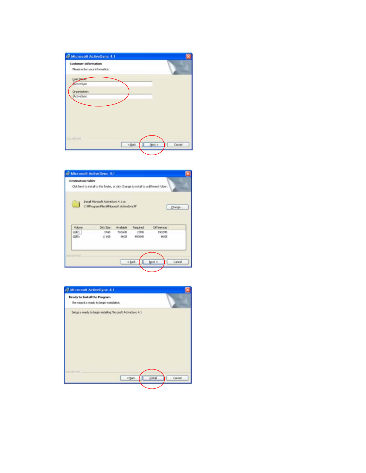
Detect the directory for installation and select “Next”.
Select “Install”.
Installing
Page 66 11/30/2006
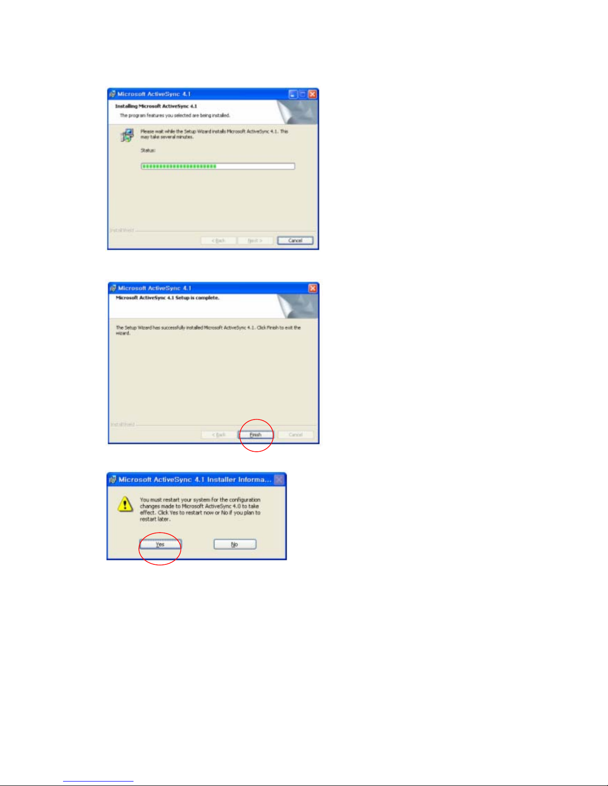
Select “Finish” to complete the installation.
Select “Yes” to reboot the Pc.
9.2 USB / Serial / IrDA ActiveSync
To operate ActiveSync program in PC
Start > Program > Microsoft ActiveSync
Page 67 11/30/2006

For PC ActiveSync settings File > Connection Settings >
Select between USB ActiveSync Connections / Serial ActiveSync Connections / IrDA
ActiveSync Connections as per requiremen t .
In USB ActiveSync connections, check “Allow USB connections” and Select “Ok”.
Page 68 11/30/2006

In Serial ActiveSync Connections
Allow connections to one of the following, select COM1
In IrDA ActiveSync Connections
Allow connections to one of the following, select Infrared port IR
To set PDA ActiveSync Control Panel > PC Connection double click
Page 69 11/30/2006
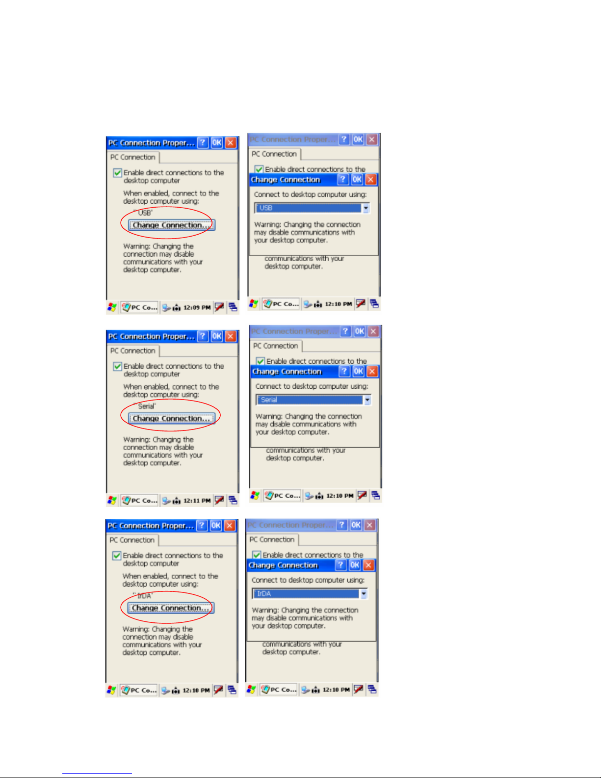
PC Connection has to be
USB for USB ActiveSync Connections ,Serial for Serial ActiveSync Connections and
IrDA for IrDA ActiveSync Connections, else select “Change Connection”
Page 70 11/30/2006

Connect ActiveSync cable to PDA and PC for USB and Serial connections
Use IrDA ports on rear side of PDA and PC for IrDA connections
Sync cable IrDA ports
Program > Communication > USB ActiveSync / Serial ActiveSync / IrDA ActiveSync
Connecting
Page 71 11/30/2006
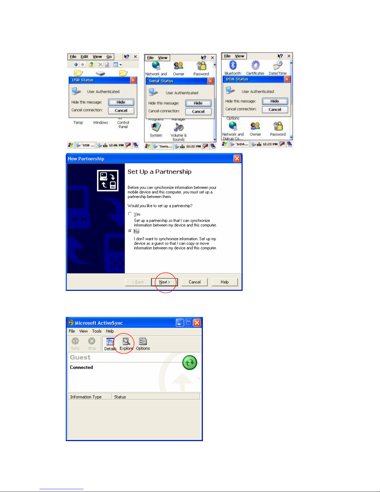
As soon as the connection is successful following dialog box will be displayed on host PC. To see
the files on SmartCompact , click on explorer .
Page 72 11/30/2006

Also there will be status icon in system tray to show the status of connection between
SmartCompact and Host PC. User can open ActiveSync program by clicking on the icon.
Connected
Disconnected
Data Transfer
9.3 Blueman ActiveSync
Select Blueman Manager > Connection > Scan for ActiveSync devices
Page 73 11/30/2006
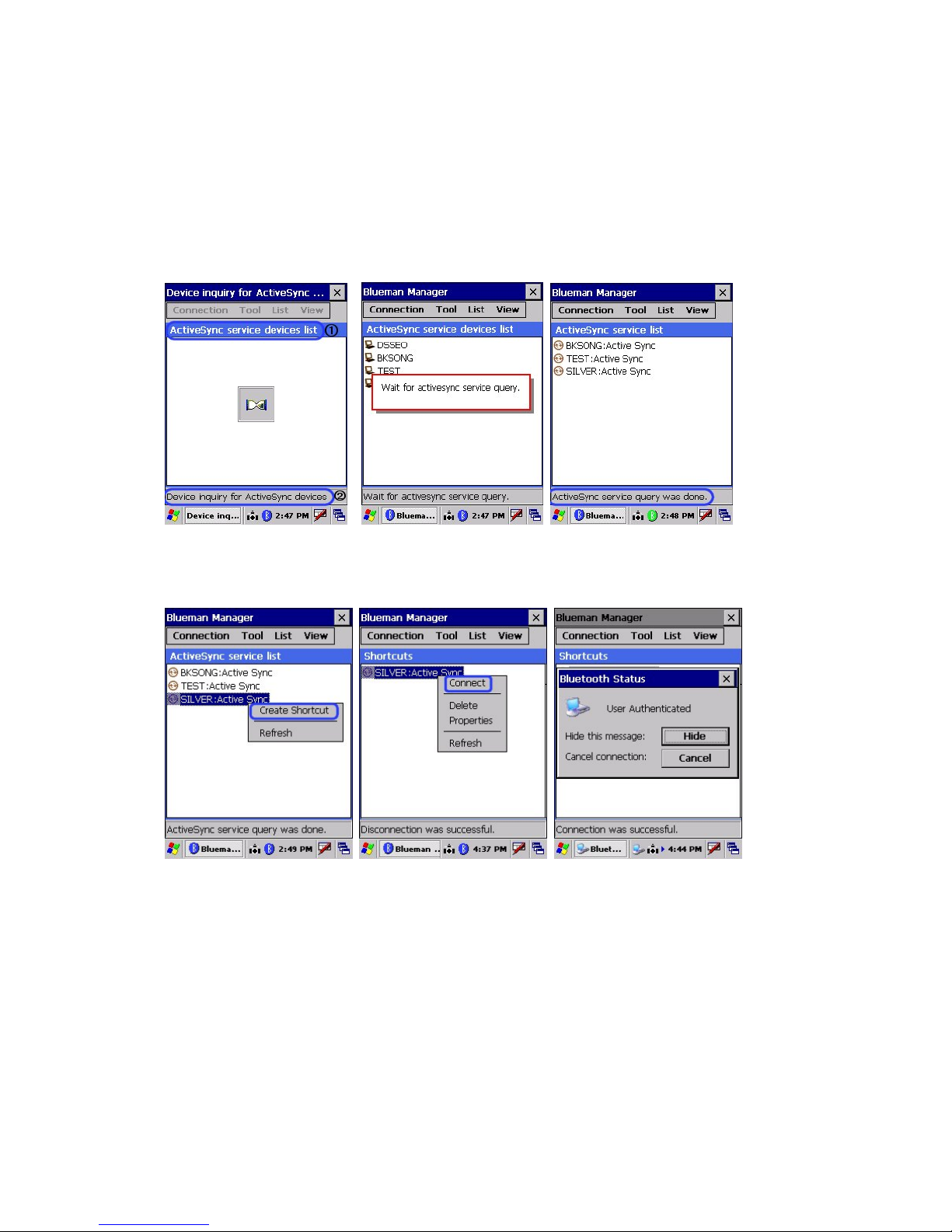
Scan for ActiveSync devices
- This section describes how to make a shortcut to search and connect all Bluetooth devices
with ActiveSync service.
Search Bluetooth devices which support ActiveSync service
<Device searching screen> < Service query Screen > < List complete Screen >
Select device & click create Double click on device icon Message after successful
Shortcut to get popup menu, select connection
Connect
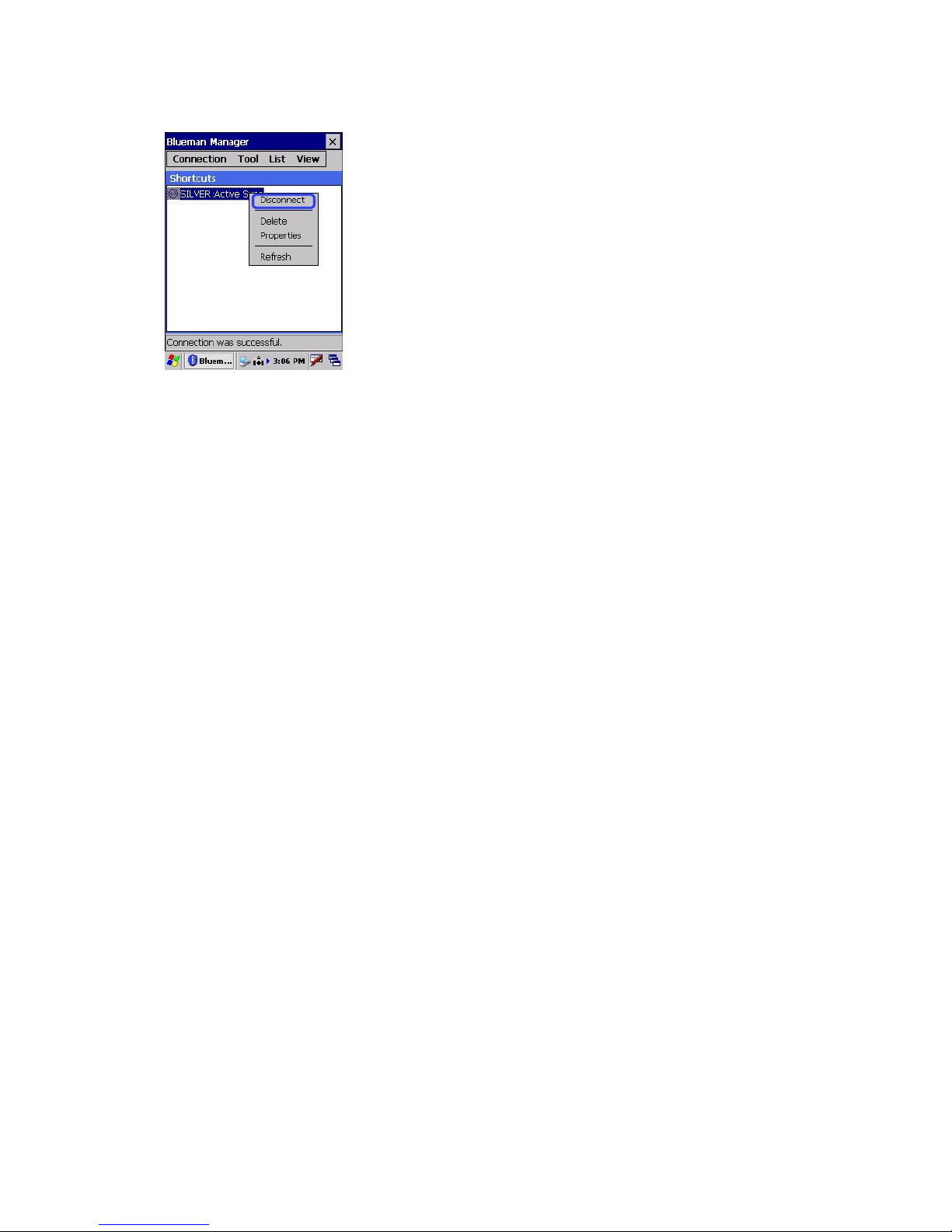
To disconnect the service
Page 74 11/30/2006
Page 75 11/30/2006

Appendix A
SmartCompact Specification Highlights
Physical and Environmental Characteristics
Dimensions: 6.6” L x 3.0” W x 1.2 ” D (168 mm L x 78 mm W x 33 mm D), 500 g
Display Diagonal: 3.5” (89 mm) diagonal, 2.2” W x 2.9” L (56 mm W x 74 mm L)
Sealing: IP 54 compatible
Operating Temperature:
Storage Temperature:
Humidity: 5% - 95% non-condensing
Drop Survival: Withstands multiple 4 ft (1.2 meter) drops to concrete
Performance Characteristics
Processor: 32bit RISC Microprocessor
System Memory: 128 MB SDRAM / 128MB Flash ROM
Display: 240 (W) x 320 (L) (QVGA) transflective TFT 256K Color LCD, 80 NIT with resistive
Keyboard: 16 + 1 alphanumeric keyboard, 2 scanner buttons, navigation, power button,
Operating System /
Software
System Expansion: 1 Compact Flas h Type II Slot (external access, supports 3.3V)
+14° F to +122° F (-10° C to +50° C)
-4° F to +140° F (-20° C to +60° C)
touch screen, Sunlight Readab le
software reset butt o n
Microsoft® WinCE .NET 5.0, Internet Explorer, InBox, Async, etc., s/w update from
Compact Flash
1 SD Card Slot (external access)
Application Development Microsoft Embedded Visual C++®, Microsoft Visual Studio .NET®, to build web
IrDA: Standard IrDA 1.2 compliant SIR Support, in – in (20cm – 30cm) distance
Bar-code Scanning: For SmartCompact-1D -- 1D, CCD type scanner
LED One triple-color LED for alarm notification / charger indicator. One duo color LED
Audio & vibrator One mono speaker and one coin type vibrator
USB Support USB 1.1 Compliant Function
Page 76 11/30/2006
services and applications for the Microsoft .NET Compact Framework.
For SmartCompact -2 D – 1D, 2D Im ag er (CCD type sca n ner)
for scanner indicator, One duo color LED for wireless

Data Capture Characteristics
Light source: 617 nm Highly visible LED
Scan rate Decoded operation 500 scans/s auto-adaptive
Un-coded operation 200 opera tion 200 scans/s
Scan angle
40°
Reading distance Up to 90 cm (35 in)
Ambient light Works in any lighting conditions
Print contrast Down to 25%
Decode software suites
and symbologies
supported
For SmartCompact-1D
Codabar, Codablock A & F. Code 11, Code 39, Code 93/93I, Code 128, EAN,
Industrial and Standard 2 of 5, interleaved 2 of 5, ISBT 128, Matrix, MacroPDF
417 (unbuffered mode), MicroPDF417, MSI, PDF417, Plessey, RSS, Telepen,
UCC EAN 128, UPC-A and UPC-E
For SmartCompact-2D
2 Dimensional : PDF417, MicroPDF 417, MaxiCode, Data Matrix , QR code, Aztec,
Aztec Mesas, Code 49, EAN-UCC Composite, Snowflake, Dataglyphs
Linear : Code 39, Code 128, Codabar, UPC, EAN, Interleaved 2 of 5, Reduced
space Symbology, Code 93, Codablock F, BC412
Postal : Postnet, Planet code, British Post, Canadian Post, Japanese Post, KIX
(Netherlands) post
Network Characteristics
Wireless: 802.11b/g 2.4 GHz (Optional)
Remote Modem (WAN): CDMA1-X1 (Class B), GPRS(GSM) (optional) through Comp act Flash Slot
GPS: GPS Module (optional) through Compact Flash Slot
Regulato ry Approvals
FCC Class B , MIC, CE
Power Supply
Power and Battery
System
Page 77 11/30/2006
OCR Fonts: OCR-A and OCR-B
Internal Bluetooth Module (Serial interface) : 10mW (Class 2) 1.1/1.2 (Optional)
2000 mAH Li-ion removable battery (10 operation and 100 standby hours), 5 hour
recharge time
110 mAh rechargeable built in backup battery, holding system data for 2.7 hours

without main battery
1 DC IN jack, power adapter w ith 100-240Vac, input and 5V/3A DC output
Power Management: Support for Xscale application modes, including Turbo
(Maximum power 400MHz) , Normal, Idle, and Sleep (Less power 20 0MHz)
Hot swappable battery – Main bat tery can be changed without switching off the
unit.
Optional : 3000 m AH battery
Page 78 11/30/2006

Appendix B
Version Table
Version: 1 Release Date: 11/30/2006
Page 79 11/30/2006

Additional page
Regulatory Information
FCC compliance Information
This device complies with part 15 of FCC Rules.
Operation is subject to the following two conditions:
1. This device may not cause harmful interference, and
2. This device must accept any interference received.
Including interference that may cause undesired operation.
Information to User
This equipment has be en t es ted an d f ound to c omply with the limits for a Clas s B dig ital de vic e, Purs ua nt
to part 15 of the FCC Rules . These lim its are designed to pr ovide reas onable protec tion against h armful
interference in a residentia l installa tio n.
This equipment gen erates , us es and can radiate radio Fr equency energy and, if not installed and used in
accordance with the instructions, may cause harmful interference to radio communications.
However, there is no guarantee that interference will not occur in a particular installation. If this
equipment does caus e harmf ul interference to r adio or tele vision recept ion, whic h can be determ ined b y
turning the equipm ent off and on, th e us er is e nc our ag ed to tr y to c orr ect the interference b y one or more
of the following measures:
- Reorient or relocate the receiving antenna.
- Increase the separati on between the equipm ent and receiver- Conn ect the equipment i nto an outlet
on a circuit different from that to which the receiver is connected.
- Consult the dealer or an experienced radio/TV technician for help.
FCC WARNING: This equipment may generate or use radio frequency energy. Changes or
modifications to th is equipment may cause harmful interference unles s the modifications are expres sly
approved in the instructi on manual. The user could lose the authorit y to operate this equipment if an
unauthorized change or modification is made.
Body-worn Operation
This device was tested for typical body-wor n operations with the back of the PDA kept 0 cm from the
body .To maintain compliance with FCC RF exposure compliance requirements, use only belt-clips,
holsters or sim ilar ac cess ories t hat m aintain a 0 c m separation distanc e bet ween the us er ’s b od y and th e
back of the PDA, inc luding the antenna, whether extended or retr acted. The use of third-party belt-clips,
holsters and similar accessories should not contain metallic components in its assembly. The use of
accessories that do not s atisfy these requirements may not com ply with FCC RF exposure composur e
compliance requirements, and should be avoided.
 Loading...