


RSD-3229 BT
OWNER’S MANUAL
Mobile Audio System
● PLL Synthesizer Stereo Radio
● Automatic Memory Storing
● Full Detachable Panel
● USB Interface
● Memory Card Interface
● Auxiliary Input Function
● Bluetooth Hands-free function &
Stereo Audio Transmission
1

CONTENTS
Installation ........................................... 3
Take out screw before installation
DIN Front-Mount (Method A)
Installing the unit
Removing the unit
DIN Rear-Mount (Method B)
Using the detachable front panel ...... 5
Wiring Connection .............................. 6
Operation............................................. 7
Location of keys ................................. 7
Basic operation ................................... 8
Switching on/off the unit
Faceplate release
Sound adjustment
System setting
Mute
..................................................
...............................
.............................
....................
..............................
.............................
...................................
.......
..............
..............
3
3
3
4
4
8
8
8
8
8
Display information
Memory Card operation..................... 10
Bluetooth operation ........................... 10
Preparing for operation
Pairing
Re-connecting
RBDS OPERATION...........................11
Making an outgoing call
Specification....................................... 12
Trouble shooting ................................13
...............................................
.............................
......................
..................................
....................
10
10
10
11
11
Loudness
Set the clock
Display information
Equalization.......................................
Reset function
Mode selection
Auxiliary input
Radio operation .................................. 9
Selecting the frequency band
Selecting station
Automatic memory storing&
program scanning
Mono/stereo
Station storing
Selecting tracks
Selecting directory up/down
...........................................
......................................
............................
...................................
..................................
....................................
............
................................
.............................
......................................
....................................
..................................
................
8
8
8
8
8
8
9
9
9
9
9
9
9
9
Pausing playing
Previewing all
Repeating the same track
Playing all tracks in random
Selecting tracks by AMS button
...................................
tracks...........................
..................
...............
...........
9
10
10
10
10
2

INSTALLATION
Notes
● Choose the mounting location where
the unit will not interfere with the normal
driving function of the driver.
● Before finally installing the unit, connect
the wiring temporarily and make sure it
is all connected up properly and the
unit and the system work properly.
● Use only the parts included with the
unit to ensure proper installation. The
use of unauthorized parts can cause
malfunctions.
● Consult with your nearest dealer if
installation requires the drilling of holes
or other modifications of the vehicle.
● Install the unit where it does not get in
the driver’s way and cannot injure the
passenger if there is a sudden stop, like
an emergency stop.
● Avoid installing the unit where it would
be subject to high temperature, such as
from direct sunlight, or from hot air,
from the heater, or where it would be
subject to dust, dirt or excessive
vibration.
DIN FRONT/REAR-MOUNT
This unit can be properly installed either
from “Front” (conventional DIN Front-mount)
or “Rear” (DIN Rear-mount installation,
utilizing threaded screw holes at the sides
of the unit chassis). For details, refer to the
following illustrated installation methods.
DIN FRONT-MOUNT (Method A)
Installation Opening
This unit can be installed in any dashboard
having an opening as shown below:
Installing the unit
Be sure you test all connections first, and
then follow these steps to install t he unit .
1. Make sure the ignition is turned off, and
then disconnect the cable from the
vehicle battery’s negative (-) terminal.
2. Disconnect the wire harness and the
antenna.
3. Press the release button on the front
panel and remove the control panel
(see the steps of “to detach the front
panel”).
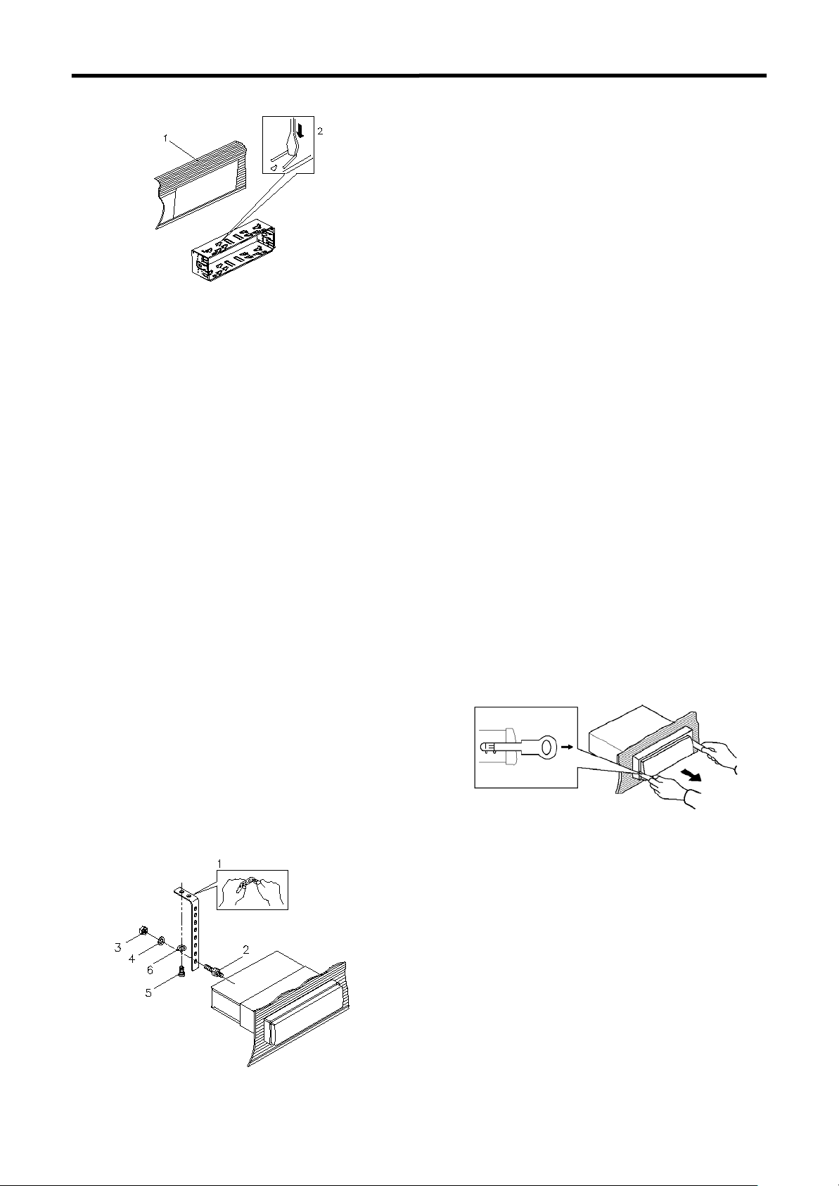
4. Lift the top of the outer trim ring then pull
it out to remove it.
5. The two supplied keys release tabs
inside the unit’s sleeve so you can
remove it. Insert the keys as far as they
will go (with the notches facing up) into
the appropriate slots at the middle left
and right sides of the unit. Then slide
the sleeve off the back of the unit.
(1) Front panel; (2) Outer tri m ring;
(3) Sleeve; (4) L key; (5) R key
6. Mount the sleeve by inserting the sleeve
into the opening of the dashboard and
bend open the tabs located around the
sleeve with a screwdriver. Not all tabs
will be able to make contact, so
examine which ones will be most
effective. Bending open the appropriate
tabs behind the dashboard to secure
the sleeve in place.
3
INSTALLATION
(1) Dashboard (2) Taps
7. Reconnect the wire harness and the
antenna and be careful not to pinch any
wires or cables.
8. Slide the unit into the sleeve until it
locks into place.
9. To further secure the unit, use the
supplied metal strap to secure the
back of the unit in place. Use the
supplied hardware (Hex Nut (M5mm)
and Spring Washer) to attach one end
of the strap to the mounting bolt on the
back of the unit. If necessary, bend the
metal strap to fit your vehicle’s mounting
area. Then use the supplied hardware
(Tapping Screw and Plain Washer) to
attach the other end of metal strap to a
solid metal part of the vehicle under the
dashboard. This strap also helps ensure
proper electrical grounding of the unit.
Note to install the short threading
terminal of the mounting bolt to the back
of the unit and the other long threading
terminal to the dashboard.
(1) Metal Strap; (2) Mounting Bolt;
(3) Hex Nut; (4) Spring Washer;
(5) Tapping Screw (5x25mm); (6) Plain Washer
10. Reconnect the cable to the vehicle
battery’s negative (-) terminal. Then
replace the outer trim ring and install the
unit’s front panel (see the steps of “to
install the front panel”).
Removing the unit
1.
Make sure the ignition is turned off, then
disconnect the cable from the vehicle
battery’s negative (-) terminal.
2.
Remove the metal strap attached the
back of the unit (if attached).
3.
Press the release button to remove the
front panel.
4.
Lift the top of the outer trim ring then pull
it out to remove it.
5.
Insert both of the supplied keys into the
slots at the middle left and right sides of
the unit, then pull the unit out of the
dashboard.
DIN REAR-MOUNT (Method B)
If your vehicle is a Nissan, Toyota, follow
these mounting instructions.
Use the screw holes marked T (Toyota), N
(Nissan) located on both s ides of the unit to
fasten the unit to the factory radio mounting
brackets supplied with your vehicle.
4

INSTALLATION
To Install the Control Panel
To install the control panel, insert the panel
int the housing and make sure the panel is
properly installed. Otherwise, abnormality occurs
on the display or some keys will not function
properly.
To fasten the unit to the factory radio
mounting brackets.
Align the screw holes on the bracket with
the screw holes on the unit, and then
tighten the screws (5x5mm) on each side.
Note: the outer trim ring, sleeve and the
metal strap are not used for method B
installation.
To Detach the Front Panel
1.Press the release button ( ) on the front
panel and pull off the control panel.
Precautions when handling
1. Do not drop the front panel.
2. Do not put pressure on the display or control
buttons when detaching or
re-installing the front panel.
3. Do not touch the contacts on the front panel or
on the main unit body. It may result in poor
electrical contact.
4. If any dirt or foreign substances adhered on
the contacts, they can be removed with a
clean and dry cloth.
5. Do not expose the front panel to high
temperatures or direct sunlight in anywhere.
6. Keep away any volatile agents (e.g. benzene,
thinner, or insecticides) from touching the
2.Keep the control panel into the case.
surface of the front panel.
7. Do not attempt to disassemble the front
panel.
5

(10A)
WIRING CONNECTION
Connector A
1. N.C
2. N.C
3. N.C
4. MEMORY +12V (YELLOW)
5. AUTO ANTENNA OUTPUT (BLUE)
6. N.C
7. +12V (TO IGNITION KEY) (RED)
8. GROUND (BLACK)
Connector B
1. REAR RIGHT SPEAKER (+) (VIOLET)
2. REAR RIGHT SPEAKER (-) (VIOLET/BLACK)
3. FRONT RIGHT SPEAKER (+) (GRAY)
4. FRONT RIGHT SPEAKER (-) (GRAY/BLACK)
5. FRONT LEFT SPEAKER (+) (WHITE)
6. FRONT LEFT SPEAKER (-) (WHITE/BLACK)
7. REAR LEFT SPEAKER (+) (GREEN)
8. REAR LEFT SPEAKER (-) (GREEN/BLACK)
6

OPERATION
LOCATION OF KEYS
1. (release button)
2. VOLUME Buttons(SEL/MUNE)
3. LCD
4.
/MUTE
5. buttons
6. DISP
7. (hang up)/BND
8. MON
9. buttons
10. AMS
AUX IN
11.
USB interface
12.
13. MODE/PTY/ (pick up)
14. Mic (microphone)
15. Reset button
16. EQ/TA
17. 6/DIR+
18. 5/DIR-
19. 4/RDM
20.1-6 preset buttons
21.
3/RPT
22. 2/INT
23. 1/PAU
24. Memory Card interface
7

Use the volume knob to the left or right to
Volume knob
OPERATION
BASIC OPERATION
SWITCHING ON/OFF THE UNIT
Press button to turn on the unit, When
the unit is on, press and hold button to
turn the unit off.
FACEPLATE RELEASE
Press button to detach the removable
faceplate.
SOUND ADJUSTMENT
Shortly press Volume knob button to enter
AUDIO SETTING mode, use Volume knob
button to select the desired adjustment
mode. The adjustment mode will change in
the following order:
BAS →→ TRE →→ BAL →→ FAD
(Bass) (Treble) (Balance) (Fader)
Adjust the volume
SYSTEM SETTING
Press and hold the volume button (1) on the
front panel to enter system setting mode.
Then briefly press the volume button (1) to
select the item you want to change and
rotate the volume knob (1) to change the
corresponding setting.
1) BEEP ON/OFF
Use to set Beep sound
on or off.
2) P-VOL
Use Volume Up/Down button to select
the volume level when the unit turns on.
3) AREA EUR/USA
Use Volume Up/Down button to set EUR
or USA area frequency spacing
MUTE
Shortly press MUTE button will mute the
sound instantly, press it again will resume
the sound.
LOUDNESS
Press LOU button for several seconds to
switch loudness function on, and “LOUD”
will appear on the LCD.
Press it for several seconds again to
release this function, and “LOUD” will
disappear.
SET THE CLOCK
Press the DISP button shortly until the
clock is shown on the LCD display. Then
hold down DISP button until the clock
flashes. Then rotation the volume button to
change minutes or to change hour s .
DISPLAY INFORMATION
Press DISP button (18) to operate as the
conversion of eac h di spl ay mode.
EQUALIZATION
Press EQ/TA button to turn on equalization
function and to select desired audio mode.
There are several kinds of mode as below:
→ FLAT→CLASSICS→POP →ROCK →EQ
RESET FUNCTION
RESET button must be activated with either
a ballpoint pen or thin metal object. The
RESET button is to be activated for the
following reasons:
- Initial installation of the unit when all
wiring is completed.
- All the function buttons do not operate.
- Error symbol on the display.
Note: if press RESET button, the unit
can’t work yet, please use a cotton swab
soaked in isopropyl alcohol to clean the
socket on the front panel.
MODE SELECTION
Shortly press MODE button to select
the desired mode, such as Radio, USB,
CARD, AUX, DAB mode.
When there isn’t an USB or CARD
connected to the unit, the corresponding
mode will be skipped.
For Bluetooth function, when pairing
successful, you can select BT mode
through MODE button.
OFF
8

/
OPERATION
AUXILIARY INPUT
The unit can be connected to a portable
audio player through the AUX IN jack on
the front panel. After finishing the
connection, you can press MODE button
on the front panel to switch the mode to
AUX IN mode.
RADIO OPERATION
SELECTING THE FREQUENCY BAND
At radio mode, press BND button shortly to
select the desired band.
The reception band will change in the
following order:
FM1 FM2 FM3 MW(AM)
SELECTING STATION
Shortly press / buttons to activate
automatic seek function. Press for several
seconds until “MANUAL” appears on the
display, the manual tuning mode is selected.
If both buttons have not been pressed for
several seconds, they will return to seek
tuning mode and “AUTO” appears on the
display then disappears.
AUTOMATIC MEMORY STORING &
PROGRAM SCANNING
- Automatic memory storing
Press AMS button for several seconds
“SEARCH” will appear on LCD.
the radio will search from the current
frequency and checks the signal
strength until one cycle search is
finished. And then 6 strongest stations
are stored into the corresponding preset
number button.
- Program scanning
Press AMS button shortly to scan preset
station. And the corresponding station
number P1~P6 will flash on LCD.
NOTE:
In MP3 playback mode,press the AMS
key selections.
MONO/STEREO
Press MON button to select mono or stereo
mode. You can sometimes improve
reception of distant stations by selection
mono operation.
STATION STORING
Press any one of the preset buttons (1 to 6)
to select a station, which had been stored
in the memory. Press this button for several
seconds to store the current station into the
number button.
USB PLAY OPERATION
In the front panel of the unit, there is an
USB interface. You can connect an USB
device through this interface.
When you connect an USB device through
the interface, the unit will search the MP3
files or WMA files in the USB driver and
start to play MP3 files or WMA files
automatically.
If in other mode, you can also press MODE
button to select USB mode.
SELECTING TRACKS
Press will skip to the previous next
track. Track number will be showed on
display.
Press and hold will fast reverse
Forward. Normal play starts when you
release the button.
SELECTING DIRECTORY UP/DOWN
Press DIR- button or DIR+ button to select
directory downward or upward. If the
MP3/WMA file does not contain any
directory, there is no function of pressing
DIR- button or DIR+ button.
PAUSING PLAYING
Press PAU button to pause the play.
Press it again to resume play.
9

OPERATION
PREVIEWING TRACKS
Press INT button to play first several
seconds of each track. Press again to stop
intro and listen to track.
REPEATING THE SAME TRACK
Press RPT button to continuously repeat
the same track. Press it again to stop
repeat.
PLAYING ALL TRACKS IN RANDOM
Press RDM button to play all tracks on the
USB in random order. Press again to
cancel the function.
SELECTING TRACKS BY AS/PS/
Navi-SCH BUTTON
Press AMS button, then You
can use the volume buttons to select the
track directly.
Then press the VOLUME button or BND
button to start playing the track.
DISPLAY INFORMATION
Press DISP button to show the following
information, such as the clock, ID3 TAG (if
available: song title, directory name, artist
name, other contents…) (FOR WITH MP3
ID3 FUNCTION VERSION ONLY) and
other information.
Note:
■ The main unit can only support the
standard USB-memory device which
is approved by Microsoft.
■ USB MP3 player is not a standard
which means different brand name or
different models have their own
standard. So our product cannot support
every MP3 player.
■ When connecting an MP3 player and
there has normal battery in the player
(non rechargeable battery), you should
remove the battery from the MP3 player
then connect it to the USB interface.
Otherwise, it may cause battery burst.
■ When in USB play mode, be sure not to
remove the USB driver from the USB
interface.
MEMORY CARD OPERATION
There is a memory card interface on the
housing the unit.
When you insert a memory card in the
memory card interface, the unit will search
the MP3 files or WMA files in the card and
start to pl ay MP3 fil es or WMA files
automatically.
The operation is the same with the USB
operation described above.
CAUTION
When there are important files in the USB
device or the memory card, do not connect
it to the main unit to play. Because any
wrong operation may cause files loss. And
our company assumes no responsibility for
this.
BLUETOOTH OPERATION
PREPARING FOR OPERATION
(1) When use Bluetooth, please make sure
the mobile phone supports Bluetooth
function.
(2) For the different kind of mobile phone,
Bluetooth emissive power has some
difference. To get the best conversation
quality, it is commended that the
distance between the mobile phone and
the unit is within 3m. And please don’t
put any metal object or any obstacle
between the path of the mobile phone
and the unit.
PAIRING
1) Long pressing MODE button until
LCD display PAIRING to enter paring
mode. On the mobile phone, select
the Bluetooth set up. (Please refer to
the instruction manual of your mobile
phone on how to operate Bluetooth.)
2) “CarBT” should appear in the list on
your mobile phone, please select
“CarBT” and then input password
“0000”.
3) The unit has auto pairing function, it will
searching the Bluetooth mobile phone
automatically.
4) When successful paired, the Bluetooth
sign will be displayed on LCD.
5) If pairing failed, try to pair again within
several seconds. You can refer to the
operation about your mobile phone,
delete the device that just searching for
and repair again.
10

OPERATION
RE-CONNECTING
This unit is built-in auto-reconnection
function. In some conditions, the unit will
auto reconnect with the mobile phone (note:
the mobile phone must have been paired
with the unit before.)
Before dialing you need to confirm the
Bluetooth sign is displayed on LCD.
Within ten seconds in the following
conditions:
a. when you turn off the unit and then turn it
on again.
b. switch off the ACC wire and switch it on
again.
c. press (release) button to release the
front panel and install the panel again.
Press button, ‘NOT PAIR’ may be
displayed on the LCD. You can wait for
several seconds to let the unit reconnection
automatically During reconnection, LCD
will show “CONN TRY” several times and
then show “CONN OK” if successfully
connect.
RDS OPERATION
- Using PTY/AF to Select Program
Press PTY/AF button once to select
With PTY ON, press PTY/AF button
the PTY group. Then rotate the
volume knob to select the PTY
program.
After selecting the PTY program the
unit searches for the respective
stations and stops when a station is
found.
again to cancel the PTY function.
Note: When selecting AREA EUR in system
setting, hold press PTY/AF button to switch
on or off RDS function. Whenever RDS is
switch on, symbol “AF” appears on the
display.
MAKING AN OUTGOING CALL
Making an outgoing call by inputting the
phone number manually.
Press button on the front panel. Use
0~9, *, # buttons to enter the phone
number you want to dial. Then press
button again will call the number.
Note: if you input the wrong number,
shortly press CLR button will clear it.
Press and hold CLR button will clear all
number.
TRANSFER THE CALL BETWEEN
MOBILE PHONE AND THE UNIT
During the talking mode, you can press
button to transfer the phone call between
the mobile phone and the unit.
Note:
If you transfer the call to mobile phone, the
mute of the present mode will be released
at the same time.
- Listening to Traffic Ann ouncement
Press and hold EQ/TA button , the unit
will search Traffic Announcement
automatically. Press and hold EQ/TA
button . TA mode will exit.
11

SPECIFICATION
GENERAL
Power Supply Requirements : DC 12 Volts, Negative Ground
Tone Controls
- Ba ss (at 100 Hz) : ±10 dB
- Treble (at 10 kHz) : ±10 dB
Maximum Output Power : 4x25 watts
Current Drain : 10 Ampere (max.)
USB/MEMORY CARD PLAYER
Signal to Noise Ratio : More than 55 dB
Channel Separation : More than 50 dB
Frequency Response : 40Hz – 18 kHz
RADIO
FM
Frequency Coverage 87.5 to 108 MHz(Europe)
87.5 to 107.9 MHz (USA)
IF 10.7 MHz
Sensitivity (S/N=30dB) 10 dBu
Stereo Separation >25dB
AM
Frequency Coverage 522 to 1620 KHz(Europe)
530 to 1710 KHz (US A)
IF 450 kHz
Sensitivity (S/N=20dB) 36 dBu
Note:
Specifications and design are subject to modification, without notice, due to
improvements in technology.
12

TROUBLE SHOOTING
Before going through the checklist, check wiring connection. If any of the
problems persist after checklist has been made, consult your nearest service dealer.
Symptom
No power.
No sound.
The
operation
keys do not
The radio
does not
Work. The
radio station
automatic
selection
Caus Solutio
The car ignition switch
is not on.
The fuse is blown.
Volume is in minimum
Wiring is not
properly connected.
The built-in
microcomputer is not
operating properly due to
The antenna cable is
not connected.
The signals are too weak.
If the power supply is
connected to the car
accessory circuits, but the
engine is not moving, switch
the ignition key to “ACC”.
Replace the fuse.
Adjust volume to a desired level.
Check wiring connection.
Press the RESET button.
Front panel is not properly fixed
into its place.
Insert the antenna cable firmly.
Select a station manually.
13

FCC NOTE
This device complies with Part 15 of the FCC Rules.
Operation is subject to the following two conditions: (1) this device may not cause harmful interference, and
(2) this device must accept any interference received, including interference that may cause undesired
operation.
THE MANUFACTURER IS NOT RESPONSIBLE FOR ANY RADIO OR TV INTERFERENCE CAUSED BY
UNAUTHORIZED MODIFICATIONS OR CHANGE TO THIS EQUIPMENT. SUCH MODIFICATIONS OR
CHANGE COULD VOID THE USER’S AUTHORITY TO OPERATE THE EQUIPMENT.
This equipment has been tested and found to comply with the limits for a Class B digital device, pursuant to
part 15 of the FCC Rules. These limits are designed to provide reasonable protection against harmful
interference in a residential installation. This equipment generates, uses and can radiate radio frequency
energy and, if not installed and used in accordance with the instructions, may cause harmful interference to
radio communications. However, there is no guarantee that interference will not occur in a particular
installation. If this equipment does cause harmful interference to radio or television reception, which can be
determined by turning the equipment off and on, the user is encouraged to try to correct the interference by
one or more of the following measures:
-- Reorient or relocate the receiving antenna.
-- Increase the separation between the equipment and receiver.
-- Connect the equipment into an outlet on a circuit different from that to which the receiver is connected.
-- Consult the dealer or an experienced radio/TV technician for help.
This device complies with FCC’s RF radiation exposure limits set forth for an uncontrolled environment,
and it must not be collocated or operated in conjunction with any other antenna or transmitter.
 Loading...