

Page 1

MC1600 Extreme Edge Server
Installation and Use
P/N: 6806870A02B
January 2020
Page 2

© 2020 SMART Embedded Computing™, Inc.
All Rights Reserved.
Trademarks
The stylized "S" and "SMART" is a registered trademark of SMART Modular Technologies, Inc. and “SMART Embedded
Computing” and the SMART Embedded Computing logo are trademarks of SMART Modular Technologies, Inc. All other names
and logos referred to are trade names, trademarks, or registered trademarks of their respective owners. These materials are
provided by SMART Embedded Computing as a service to its customers and may be used for informational purposes only.
Disclaimer*
SMART Embedded Computing (SMART EC) assumes no responsibility for errors or omissions in these materials. These
materials are provided "AS IS" without warranty of any kind, either expressed or implied, including but not limited to,
the implied warranties of merchantability, fitness for a particular purpose, or non-infringement. SMART EC further does
not warrant the accuracy or completeness of the information, text, graphics, links or other items contained within these
materials. SMART EC shall not be liable for any special, indirect, incidental, or consequential damages, including without
limitation, lost revenues or lost profits, which may result from the use of these materials. SMART EC may make changes to
these materials, or to the products described therein, at any time without notice. SMART EC makes no commitment to update
the information contained within these materials.
Electronic versions of this material may be read online, downloaded for personal use, or referenced in another document as a
URL to a SMART EC website. The text itself may not be published commercially in print or electronic form, edited, translated,
or otherwise altered without the permission of SMART EC.
It is possible that this publication may contain reference to or information about SMART EC products, programming, or services
that are not available in your country. Such references or information must not be construed to mean that SMART EC intends
to announce such SMART EC products, programming, or services in your country.
Limited and Restricted Rights Legend
If the documentation contained herein is supplied, directly or indirectly, to the U.S. Government, the following notice shall apply
unless otherwise agreed to in writing by SMART Embedded Computing.
Use, duplication, or disclosure by the Government is subject to restrictions as set forth in subparagraph (b)(3) of the Rights in
Technical Data clause at DFARS 252.227-7013 (Nov. 1995) and of the Rights in Noncommercial Computer Software and
Documentation clause at DFARS 252.227-7014 (Jun. 1995).
SMART Embedded Computing, Inc.
2900 S. Diablo Way, Suite 190
Tempe, Arizona 85282
USA
*For full legal terms and conditions, visit
www.smartembedded.com/ec/legal
Page 3

Table of Contents
About this Manual ...............................................................11
Safety Notes....................................................................15
Notice de Sécurité ...............................................................25
Sicherheitshinweise .............................................................37
1 System Overview ............................................................49
1.1 Introduction .............................................................49
1.2 Front Panel Interfaces ....................................................49
1.3 Cooling ................................................................50
1.4 Grounding ..............................................................51
1.5 Block Diagram ..........................................................52
1.6 Extreme Edge Server Base Board ...........................................53
1.6.1 CPU SKU Support ..................................................54
1.6.2 Memory Controller ..................................................54
1.6.2.1 Real Time Clock ............................................55
1.6.2.2 Trusted Platform Module (TPM) ................................55
1.7 Interfaces ..............................................................55
1.7.1 PCI Express Interfaces ..............................................55
1.7.1.1 PCI Express Gen3 ..........................................55
1.7.1.2 PCI Express Gen2 ..........................................56
1.7.2 Ethernet Interface...................................................57
1.7.2.1 Gigabit Ethernet Controller ....................................57
1.7.2.2 PCIe-Based Gigabit Ethernet ..................................57
1.7.2.3 10 Gigabit Ethernet Controller .................................57
1.7.3 SPI Interface ......................................................57
1.7.4 USB Interface......................................................58
1.7.4.1 USB 3.0 Ports (xHCI) ........................................58
1.7.4.2 USB 2.0 Ports (EHCI) .......................................58
1.7.5 UART Interface ....................................................58
1.7.6 SMBus and I2C Interface .............................................59
1.7.7 LPC Interface ......................................................60
1.7.8 PECI Interface .....................................................60
1.8 10 Gigabit Ethernet .......................................................61
MC1600 Extreme Edge Server Installation and Use (6806870A02B) 3
Page 4

Table of Contents
1.8.1 Ethernet Switch ....................................................61
1.8.2 SFP+ Ports........................................................62
1.8.3 Synchronous Ethernet and IEEE 1588 Support............................62
1.8.3.1 Synchronous Ethernet PLL ...................................62
1.8.3.2 IEEE 1588 Support .........................................63
1.9 PCIe Slot ...............................................................63
1.10 Storage ................................................................64
1.10.1 Supported NVMe Modules............................................64
1.11 Connectors .............................................................65
1.11.1 PCI Express Connector ..............................................65
1.11.2 -48V Power Connector...............................................68
1.11.3 SFP+ Module Connectors ............................................69
1.11.4 RJ-45 Ethernet Connectors ...........................................69
1.11.5 USB 2.0 Connector .................................................70
1.11.6 USB 3.0 Connectors ................................................70
1.11.7 DDR4 DIMM Connectors .............................................70
1.11.8 NVMe Module Connectors............................................74
1.12 Baseboard Management Controller (BMC) ....................................76
1.12.1 BMC Subsystem Devices.............................................76
1.12.2 BMC Subsystem Features ............................................77
1.12.3 BMC Private I2C Buses ..............................................78
1.13 Programmable Logic ......................................................78
1.13.1 CPU CPLD ........................................................78
1.13.2 Glue CPLD ........................................................79
1.14 Power Supply ...........................................................80
1.14.1 Power Architecture..................................................80
1.14.2 Payload Power-Up Sequence .........................................80
1.14.3 -48V Power Domain.................................................81
1.14.3.1 Heater Circuit ..............................................81
1.15 Clock Structure ..........................................................81
1.15.1 Processor Clocks ...................................................81
1.15.2 Other Clocks ......................................................81
1.16 Reset Structure ..........................................................82
1.17 Debugging Support .......................................................82
1.17.1 POST Code Indicators ...............................................82
1.17.2 Dip Switches ......................................................82
1.18 Ordering and Support Information ...........................................82
4 MC1600 Extreme Edge Server Installation and Use (6806870A02B)
Page 5

Table of Contents
2 Site Preparation .............................................................83
2.1 Introduction .............................................................83
2.2 Unpacking the Extreme Edge Server .........................................83
2.3 Prepare the Installation Site ................................................83
2.3.1 Power Requirements ................................................84
2.3.2 Dimensions and Weight ..............................................84
2.4 ESD Prevention .........................................................85
2.5 Mounting Options ........................................................85
2.6 Electromechanical .......................................................86
2.7 Environmental ...........................................................86
2.7.1 Environmental Conditions ............................................86
2.7.2 Electronic Waste Disposal ............................................87
2.8 Regulatory Compliance ...................................................87
3 FRU Installation .............................................................89
3.1 Introduction .............................................................89
3.2 Install PCIe Card .........................................................89
3.3 SFP/SFP+ Modules ......................................................90
4 System Installation ...........................................................91
4.1 Introduction .............................................................91
4.2 Before Installation ........................................................91
4.3 Install the Extreme Edge Server in the Cabinet .................................91
4.3.1 Ground the Server ..................................................92
4.3.2 Connect to the Power Feed ...........................................92
4.3.3 Connect the Serial Console ...........................................93
4.3.4 Access the Console (BIOS and OS) ....................................93
4.3.5 4.3.5 Connection of a USB Device......................................94
4.3.6 Power Up .........................................................94
4.4 Removal ...............................................................94
4.4.1 Power Down the Server ..............................................94
4.4.2 Disconnect from the Power Feed.......................................95
4.4.3 Removing the Server ................................................95
5 Software Configuration .......................................................97
5.1 Introduction .............................................................97
MC1600 Extreme Edge Server Installation and Use (6806870A02B) 5
Page 6

Table of Contents
5.2 Installed Software ........................................................97
5.2.1 Basic Blade Services (BBS)...........................................97
5.2.1.1 Default Network Configuration .................................97
5.2.1.2 Firmware Upgrade ..........................................99
5.2.1.2.1 BMC Upgrade .....................................99
5.2.1.2.2 BIOS Upgrade ....................................100
5.2.1.2.3 CPLD Upgrades ...................................102
5.2.1.2.4 CPU CPLD Upgrade Using fcu Utility: ..................103
5.2.1.3 Broadcom Switch ..........................................104
5.2.1.4 sfptool ...................................................108
5.2.2 Baseboard Management Controller (BMC) ..............................110
5.2.2.1 IPMI OEM Commands ......................................110
5.2.2.1.1 SMART EC IPMI OEM Command Summary .............111
5.2.2.1.2 Power Management ................................111
5.2.2.1.3 Chassis Power Policy ..............................114
5.2.2.1.4 Aggregated Temperature Sensors .....................116
5.2.2.1.5 Fan Control ......................................118
5.2.2.1.6 FRU Present State .................................118
5.2.2.1.7 Chassis Address Info ...............................120
5.2.3 AMI MegaRAC® Web GUI...........................................121
5.2.3.0.1 Invalid Certificate ..................................121
5.2.3.0.2 Login Page .......................................122
5.2.3.0.3 MegaRAC Dashboard ..............................122
A Related Documentation ......................................................123
6 MC1600 Extreme Edge Server Installation and Use (6806870A02B)
Page 7

List of Figures
Figure 1-1 Front Panel Connectors, PCIe Slot, LEDs, and Ground Point ................ 49
Figure 1-2 Front Panel LEDs .................................................. 49
Figure 1-3 Location of Serial and Assembly # Labels ...............................50
Figure 1-4 MC1600 Extreme Edge Server - Dual CPU Block Diagram ................. 52
Figure 1-5 High Level Broadwell-DE Block Diagram ................................ 53
Figure 1-6 CPU SMBus Architecture ........................................... 59
Figure 1-7 Synchronous Ethernet Clocking Architecture ............................ 62
Figure 1-8 BMC Block Diagram ................................................76
Figure 1-9 Power Architecture ................................................. 80
Figure 2-1 Location of Regulatory Labels ........................................88
Figure 5-1 Single CPU Variant ................................................ 98
Figure 5-2 Dual CPU Variant .................................................. 99
Figure 5-3 Insecure Connection Page - MegaRAC Web GUI ........................ 121
Figure 5-4 MegaRAC Login Page ............................................. 122
Figure 5-5 MegaRAC Dashboard ............................................. 122
MC1600 Extreme Edge Server Installation and Use (6806870A02B) 7
Page 8

List of Figures
8 MC1600 Extreme Edge Server Installation and Use (6806870A02B)
Page 9

List of Tables
Table 1-1 Front Panel LED Description ............................................50
Table 1-2 CPU SKU Support ...................................................54
Table 1-3 ECC/Non-ECC DIMM Types ............................................54
Table 1-4 PCI Express Gen3 Interfaces to PCIe Connector ............................56
Table 1-5 PCI Express Gen3 Interfaces to M.2 Modules ..............................56
Table 1-6 PCI Express Gen2 (PCH) Interfaces ......................................56
Table 1-7 Ethernet Switch Port Assignments .......................................61
Table 1-8 M.2 NVMe Module Support ............................................64
Table 1-9 PCIe Slot Connector Pinout ............................................65
Table 1-10 Input Power Connector Pinout ..........................................68
Table 1-11 SFP+ Connector Pinout ...............................................69
Table 1-12 Ethernet RJ-45 Connector Pinout ........................................69
Table 1-13 USB 2.0 Connector Pinout .............................................70
Table 1-14 USB 3.0 Connector Pinout .............................................70
Table 1-15 DDR4 DIMM Pinout ..................................................70
Table 1-16 NVMe Module Pinout .................................................74
Table 1-17 BMC I2C Bus 8 Devices ...............................................78
Table 1-18 BMC I2C Bus 7 Devices ...............................................78
Table 2-1 System Power Requirements ...........................................84
Table 2-2 Dimensions and Weight of System .......................................84
Table 2-3 Environmental Conditions ..............................................86
Table 2-4 Regulatory Standards .................................................87
Table 4-1 Serial Port Configuration Parameters .....................................93
Table 5-1 Single CPU Variant ...................................................97
Table 5-2 Dual CPU Variant ....................................................98
Table 5-3 General OEM Command Structure ......................................111
Table 5-4 SMART EC IPMI OEM Command Summary ..............................111
Table 5-5 Set FRU Instance Power State ........................................112
Table 5-6 Get FRU Instance Power State .........................................113
Table 5-7 Set Chassis Power Policy .............................................114
Table 5-8 Get Chassis Power Policy .............................................115
Table 5-9 Set Aggregated Temperature Sensor ....................................117
Table 5-10 Get Aggregated Temperature Sensor ....................................118
Table 5-11 Get FRU Present State Version 0 .......................................119
Table 5-12 Get FRU Present State Version 1 .......................................119
Table 5-13 Set Chassis Address Info .............................................120
Table 5-14 Get Chassis Address Info .............................................120
MC1600 Extreme Edge Server Installation and Use (6806870A02B) 9
Page 10

List of Tables
Table A-1 SMART EC Documentation ...........................................123
10 MC1600 Extreme Edge Server Installation and Use (6806870A02B)
Page 11

About this Manual
Overview of Contents
This manual is divided into the following sections.
Safety Notes on page 15 provides the safety information that should be observed while
operating the product.
Notice de Sécurité on page 25 provides a French translation of the safety notes section.
Sicherheitshinweise on page 37 provides a German translation of the safety notes section.
Chapter 1, System Overview on page 49 describes the MC1600 Extreme Edge Server’s
features and functionality. This chapter includes detail on front panel interfaces, cooling,
grounding, and the server’s base board. There is also information about the Baseboard
Management Controller (BMC) and ordering information.
Chapter 2, Site Preparation on page 83 provides information on unpacking the MC1600
Extreme Edge Server, safety precautions, and requirements for the product. Included are
the environmental and power requirements, mounting options, cooling considerations,
acoustic noise control, and dimensions and weight of the product.
Chapter 3, FRU Installation on page 89 describes the installation and removal of PCIe
cards and details of the SFP/SFP+ modules.
Chapter 4, System Installation on page 91 provides instructions for installing and removing
the MC1600 Extreme Edge Server in a rack or cabinet. It also gives information and
procedures for grounding, powering up and down, and disconnecting the server from the
power feed.
Chapter 5, Software Configuration on page 97 details about the preinstalled software and
firmware are presented in this chapter. CPU boot information and information on the Basic
Blade Services (BBS) which includes utilities for updating firmware and configuring
switches are described. System management and monitoring is discussed via the BMC
along with the standard IPMI implementation as well as some custom OEM commands.
Appendix A, Related Documentation on page 123 provides information on documentation
related to this product.
MC1600 Extreme Edge Server Installation and Use (6806870A02B) 11
Page 12

l
About this Manual
Abbreviations
This document uses the following abbreviations:
Abbreviation Definition
BBS Basic Blade Services
BMC Baseboard Management Controller
BIOS Basic Input Output System
CPLD Complex Programmable Logic Device
CPU Central Processing Unit
EHCI Enhanced Host Controller Interface
ESD Electro-static Discharge
IIO Integrated IO
IPMI Intelligent Platform Management Interface
MISO Master Data In
About this Manua
MOSI Master Data Out
OEM Original Equipment Manufacturer
PCIe PCI Express
PEM Power Entry Module
SFP Small Form-factor Pluggable
SKU Stock Keeping Unit (Intel SKU Numeric Digits)
SPD Serial Presence Detection
SPI Serial Peripheral Interface
TPM Trusted Platform Module
xHCI eXtensible Host Controller Interface
12 MC1600 Extreme Edge Server Installation and Use (6806870A02B)
Page 13
Conventions
The following table describes the conventions used throughout this manual.
Notation Description
About this Manual
0x00000000
0b0000
bold Used to emphasize a word
Screen
Courier + Bold
Reference
File > Exit Notation for selecting a submenu
<text> Notation for variables and keys
[text]
... Repeated item for example node 1, node 2, ..., node 12
.
.
.
..
Typical notation for hexadecimal numbers (digits are 0 through F), for
example used for addresses and offsets
Same for binary numbers (digits are 0 and 1)
Used for on-screen output and code related elements or commands.
Sample of Programming used in a table (9pt)
Used to characterize user input and to separate it from system output
Used for references and for table and figure descriptions
Notation for software buttons to click on the screen and parameter
description
Omission of information from example/command that is not necessary at
the time
Ranges, for example: 0..4 means one of the integers 0,1,2,3, and 4 (used
in registers)
| Logical OR
Indicates a hazardous situation which, if not avoided, could result in death
or serious injury
Indicates a hazardous situation which, if not avoided, may result in minor
or moderate injury
MC1600 Extreme Edge Server Installation and Use (6806870A02B) 13
Page 14
l
About this Manual
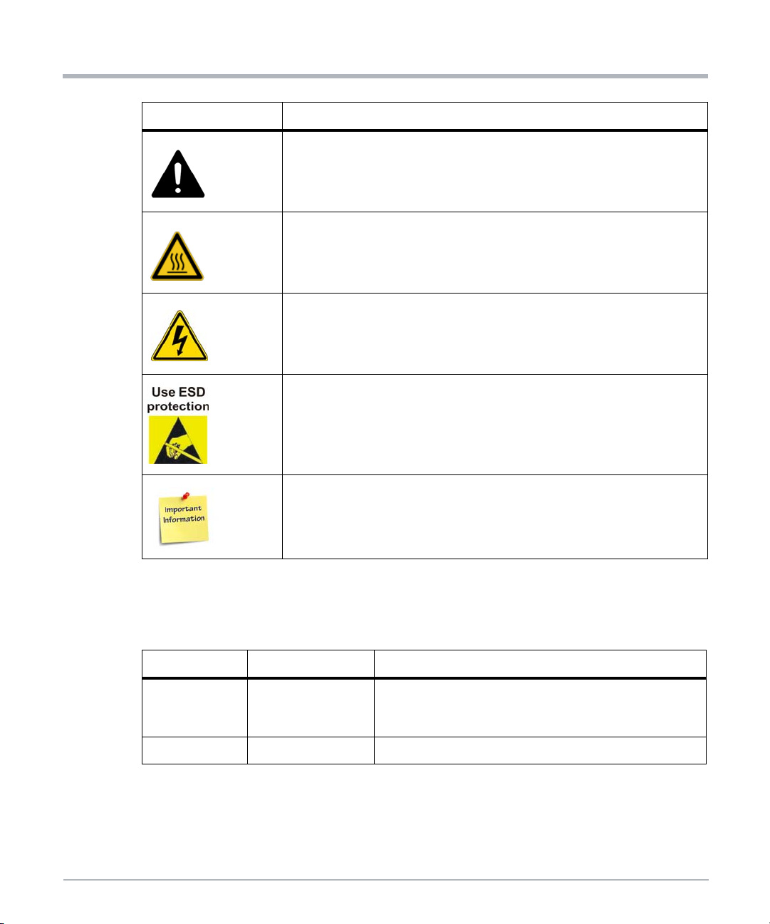
Notation Description
About this Manua
Indicates a property damage message
Indicates a hot surface that could result in moderate or serious injury
Indicates an electrical situation that could result in moderate injury or death
Indicates that when working in an ESD environment care should be taken
to use proper ESD practices
No danger encountered, pay attention to important information
Summary of Changes
This manual has been revised and replaces all prior editions.
Part Number Publication Date Description
Rebrand to SMART Embedded Computing template.
6806870A02B January 2020
6806870A02A April 2019 Initial Release
14 MC1600 Extreme Edge Server Installation and Use (6806870A02B)
Updated Safety Notes in English and German; added
French Safety Notes.
Page 15

Safety Notes
This section provides warnings that precede potentially dangerous procedures throughout
this manual. Instructions contained in the warnings must be followed during all phases of
operation, service, and repair of this equipment. You should also employ all other safety
precautions necessary for the operation of the equipment in your operating environment.
Failure to comply with these precautions or with specific warnings elsewhere in this manual
could result in personal injury or damage to the equipment.
SMART Embedded Computing intends to provide all necessary information to install and
handle the product in this manual. Because of the complexity of this product and its various
uses, we do not guarantee that the given information is complete. If you need additional
information, ask your SMART EC representative.
The product has been designed to meet the standard industrial safety requirements. It must
not be used in safety critical components, life supporting devices, or on aircraft.
Only personnel trained by SMART EC or persons qualified in electronics or electrical
engineering are authorized to install, remove or maintain the product. The information given
in this manual is meant to complete the knowledge of a specialist and must not be used as
replacement for qualified personnel.
Keep away from live circuits inside the equipment. Operating personnel must not remove
equipment covers. Only factory authorized service personnel or other qualified service
personnel may remove equipment covers for internal subassembly or component
replacement or any internal adjustment.
Do not install substitute parts or perform any unauthorized modification of the equipment or
the warranty may be voided. Contact your local SMART EC representative for service and
repair to make sure that all safety features are maintained.
EMC
The product has been tested and found to comply with the limits for a Class A digital device
in this system, pursuant to part 15 of the FCC Rules, EN 55032 Class A respectively. These
limits are designed to provide reasonable protection against harmful interference when the
product is operated in a commercial, business or industrial environment.
The product conducts, radiates and uses radio frequency energy and, if not installed
properly and used in accordance with this user documentation, may cause harmful
interference to radio communications. Operating the product in a residential area is likely
to cause harmful interference. If this occurs, the user will be required to correct the
interference at the user's expense.
Changes or modifications not expressly approved by SMART EC could void the user's
regulatory compliance. Board products are tested in a representative system to show
compliance with the above mentioned requirements. A proper installation in a compliant
system will maintain the required performance.
MC1600 Extreme Edge Server Installation and Use (6806870A02B) 15
Page 16

Safety Notes
Use only shielded cables when connecting peripherals to help assure that appropriate radio
frequency emissions compliance is maintained. For proper EMC shielding, only operate the
system with face plates installed and all vacant slots covered or populated with filler cards.
Grounding
If the product is not properly grounded, it may be damaged by electrostatic discharge.
The system contains EMI gaskets at the shelf and module level. Make sure that each of the
system's parts contact the EMI gasket.
The shelf is also fitted with an ESD jack/snap for use with conductive wrist straps. Make
sure the operator uses proper ESD protection.
This is a Class A product based on the standard of the Voluntary Control Council for
Interference by Information Technology Interference (VCCI). If this equipment is used in a
domestic environment, radio disturbance may arise. When such trouble occurs, the user
may be required to take corrective actions.
The equipment is suitable for installation in a Common Bonding Network (CBN) or Isolated
Bonding Network (IBN).
System Installation
Safety Notes
System Damage
To avoid system damage verify that the system environment meets the environmental and
power requirements given in this manual before installing the system. Before you set up
and cable your new system, consider these guidelines:
Restricted access location: Intended for installation in a restricted access location
with access by trained personnel only.
Detachable power supply cord set: The detachable power supply cord set is not
included in shipment. The detachable power supply cord set shall be an approved
type, acceptable to the authorities in the country where the equipment is installed.
Installation codes: Where applicable, this unit shall be installed in accordance with
the National Electrical Code (NEC).
Overcurrent protection: A readily accessible listed branch circuit overcurrent
protective device must be incorporated into the building wiring. For appropriate
AWG rating of the overcurrent protection device, see NEC Table 310.16 and other
national regulations.
The protective bonding conductor depends on your power distribution topology.
Make sure that you use an appropriate protective bonding conductor regarding the
rating of the branch circuit protection.
16 MC1600 Extreme Edge Server Installation and Use (6806870A02B)
Page 17

Safety Notes
Install the system safely. Make sure that cables and cords are out of the way.
Make sure that the set-up is comfortable for users.
System Damage
WARNING: The intra-building port (s) of the equipment or subassembly is suitable for
connection to intra-building or unexposed wiring or cabling only. The intra-building port (s)
of the equipment or subassembly MUST NOT be metalically connected to interfaces that
connect to the OSP or its wiring. These interfaces are designed for use as intra-building
interfaces only (Type 2 or Type 4 ports as described in GR-1089) and require isolation from
the exposed OSP cabling. The addition of primary protectors is not sufficient protection in
order to connect these interfaces metalically to OSP wiring.
System Damage
All interconnected equipment to this equipment (or to added subassemblies) is intended to
be within the same building. If this equipment (including any added subassemblies) is used
in inter-building connection, the connection shall be adequately protected against overvoltage/transient. And further Electrical Safety evaluation would be required.
System Damage
Environmental contamination can impair system operation.
Locate the system in a stable area free of excess movement and jarring and free of dust,
smoke, and electrostatic discharge (ESD). Make sure that the temperature does not
exceed the operating temperature given in the environmental requirements in this manual
and allow room for proper air flow for cooling.
Personal Injury or System Damage
A top-heavy rack can tip, causing damage to equipment and injury to personnel.
If your system is the only one in the rack, make sure to mount the system in the lowest part
of the rack. If several systems are installed in one rack, star t with the heaviest component
at the bottom. If the rack is equipped with stabilizing devices, make sure that they are
installed and extended so that the rack is secure. Then proceed to mount or service the
system.
Personal Injury or System Damage
Use caution when pulling the system out of the rack, as it could fall and cause personal
injury.
Personal Injury
The system is heavy and improper handling may lead to muscle strain or back injury.
MC1600 Extreme Edge Server Installation and Use (6806870A02B) 17
Page 18

Safety Notes
System Damage
During handling, shipping, and assembly, it is possible that pins, mounting screws, fans,
and other items became loose or damaged.
Do not operate a damaged system, as it may damage the devices that interface with the
system.
Personal Injury
High leakage current can be hazardous and cause injury.
Make an earth ground connection before connecting power to the system.
System Damage
Wrong jumper settings can make the system inoperable. Never change the settings of the
jumpers.
Card Installation
Damage of Circuits
Electrostatic discharge and incorrect product installation and removal can damage circuits
or shorten their life.
Safety Notes
Before touching the product make sure that you are working in an ESD-safe environment.
Hold the product by its edges and do not touch any components or circuits.
Product Damage
Install PCI Express (PCIe) cards in the designated slots. Installing a card in the wrong slot
may cause card or system damage.
Installing or removing the card from the system while the system is powered up may
damage the card and the system.
When installing or removing the card from the system, power down the system first.
Data Loss
The MaxCore system does not support hot swap of PCIe cards. Before opening the top
cover of the system or before installing or removing any PCIe card, make sure the system
is powered off.
Disconnect the system from any AC or DC power or turn the system board power (payload
power) off through the Board Management Controller (BMC).
For more information, refer to the MC1600 Extreme Edge Server Installation and Use
manual.
18 MC1600 Extreme Edge Server Installation and Use (6806870A02B)
Page 19

Card Malfunctioning
Incorrect card installation and removal may result in card malfunction or damage the PCIe
slot. Ensure PCIe cards are properly seated.
Operation
System Overheating–Cooling Vents
Improper cooling can lead to card and system damage and may void the manufacturer’s
warranty.
To allow for proper cooling and undisturbed airflow through the system, always operate the
system in a horizontal position. Do not obstruct the ventilation openings at the front, rear,
or sides of the system. Keep the fresh air intake of the chassis completely clear. Make sure
that the fresh air supply is not mixed with hot exhaust from other devices.
Product Damage
High humidity and condensation on product surfaces causes short circuits.
Do not operate the system outside the specified environmental limits. Make sure the
system is completely dry and there is no moisture on any surface before applying power.
Do not star t the system below 0°C unless it is an extended-temperature model.
Safety Notes
Injury
Caution: The system may be equipped with multiple power feeds. All power connection
feeds must be disconnected to de-energize the system. To reduce the risk of personal
injury, disconnect the feeds when removing power from the system.
System Damage – Air Filters
Air contamination can pollute the air filter and obstruct the air intake of the system which
may cause system overheating and component damage.
To guarantee proper airflow through the system, replace the air filters (if equipped) at least
every six months. Artesyn recommends the air filters be replaced every 90 days.
Installations vary in physical location and cleanliness. Filter replacement may be required
more often in a dusty environment. Check air filters frequently after system installation to
determine how often they must be replaced. Establish a regular replacement schedule and
keep a log to record the date of each filter replacement.
Front Panel
The front panel, including the air filter (if equipped), is mounted to the system by alignment
pins and holding clips on both sides of the system. When mounting the front panel to the
shelf, align it accurately to avoid damage to the frame or front panel.
MC1600 Extreme Edge Server Installation and Use (6806870A02B) 19
Page 20

Safety Notes
Earth Ground
This equipment is designed to permit the connection of the earthed conductor of the DC
supply circuit to the earthing conductor at the equipment. If this connection is made, all of
the following conditions must be met:
System Overheating
Safety Notes
This equipment shall be connected directly to the DC supply system earthing
electrode conductor or to a bonding jumper from an earthing terminal bar or bus to
which the DC supply system earthing electrode conductor is connected.
This equipment shall be located in the same immediate area (such as adjacent
cabinets) as any other equipment that has a connection between the earthed
conductor of the same DC supply circuit and the earthing conductor, and also the
point of earthing of the DC system. The DC system shall not be earthed elsewhere.
The DC supply source shall be located within the same premises as this
equipment.
Make sure you have an earth ground connection that is free of any disconnecting
device, such as a power switch or fuse, between the DC source and the earth
ground connector. A disconnecting device could result in the ground being
disconnected and the potential of injury from electrical shock.
If you set the fan speed manually through the Board Management Controller (BMC),
constantly monitor the system temperature to prevent overheating.
Make sure that the environmental and power requirements are met while operating the
system.
Injuries or Short Circuits
To avoid damage or personal injury, always check that no hazardous voltage is present
before servicing equipment.
Data Corruption
If power to the unit is removed while a firmware update is in progress to the product's flash
memory, the changes will not be saved or the flash memory may be corrupted. In such
case, the product is likely to remain in a non-operable state and will require reconditioning
by qualified repair services.
System Expansion
System Overload
To avoid an overload of the system, check the total power consumption of all components
installed. Make sure that the individual output current of any source stays within its
acceptable limits (see the technical specification of the respective source or component).
20 MC1600 Extreme Edge Server Installation and Use (6806870A02B)
Page 21

Loss of Safety Compliance–Using of Additional Plug-in Cards
The system may become noncompliant by the addition of plug-in cards. Regulatory
compliance is the responsibility of the system integrator.
Power Feed
Personal Injury
Touching the power feed with metallic objects on your hands, wrists, or hanging from your
neck may lead to severe personal injury through electric shock and burning when working
at the power feed or power input cables. Be extremely careful when using electrically
conductive tools near the PSUs/PEMs.
Short Circuits or Personal Injury
Make sure that the power feeds you plan to remove or attach are powered off and cannot
be switched on while you are working.
Make sure that all power feeds to the chassis are not energized. Be careful with the tools
used to prevent a short circuit.
Product Damage
Safety Notes
Improper cabling damages your product. Take extreme care not to reverse the polarity
when connecting the power cable.
Fans
System Damage
Insufficient cooling may damage the system.
When servicing, replace the fan tray (or fan modules) without delay.
Fan Replacement
When a fanis taken out of operation or is removed during a replacement procedure, system
management software may compensate for the loss by increasing the speed of any
remaining fans.
Running the fans at high speed for a long time may shorten the life of the fans and may
exceed allowable acoustic noise limits.
Replace the fan tray (or fan modules) without delay.
Personal Injury–Rotating Fans
Inserting tools or fingers into operational fans may cause personal injury.
MC1600 Extreme Edge Server Installation and Use (6806870A02B) 21
Page 22

Safety Notes
Keep clear of the fans as long as they are rotating.
When the fan is removed, extreme care should be taken while handling the fan itself. The
centrifugal forces will make the unit difficult to handle.
Cabling
Personal Injury
The cabling should follow existing cable paths using existing or similar cable fastenings.
Never change the system's cabling as delivered by SMART EC. Check proper function of
the system after cabling extensions. To avoid personal injury, always ensure that cables
are securely installed so that no one can trip over them.
Personal Injury through Electric Shock
Touching contacts and cables during system operation can cause personal injury through
electric shock.
To avoid electric shock, make sure that contacts and cables of the system cannot be
touched while the system is operating. If in doubt concerning cabling, ask your local
SMART EC representative.
Safety Notes
Cable Damage
Do not fold cables. Folding a fiber cable damages the cable and inhibits the data
transmission.
RJ-45 Connector
System Damage
RJ-45 connectors on the system or on PCIe cards are either twisted-pair Ethernet (TPE) or
E1/T1/J1 network interfaces. Connecting an E1/T1/J1 line to an Ether net connector may
damage your system.
Make sure that TPE connectors near your working area are clearly marked as
network connectors.
Verify that the length of an Ethernet cable connected to a RJ-45 TPE connector
does not exceed 100 meters or approximately 328 feet.
Make sure the TPE connector of the system is connected only to Safety Extra Low
Voltage (SELV) circuits.
If in doubt, ask your system administrator.
For more information, see the documentation of the respective product.
22 MC1600 Extreme Edge Server Installation and Use (6806870A02B)
Page 23

Laser
Battery
Safety Notes
Personal Injury
If a label with the words CLASS 1 LASER PRODUCT is affixed to your system, the unit is
equipped with a laser device. These devices contain a laser system that produces visible
or invisible laser radiation (or both) and can be harmful to the eyes.
Seek supplemental information (power, wavelength, visibility, pulse duration, applicable
standards) prior to servicing equipment. Do not look at laser device with an optical
instrument at any time.
Blade Damage
Incorrect battery installation may result in a hazardous explosion and blade damage.
Always use the same type of lithium battery as is installed and make sure the battery is
installed as described in the manual.
Data Loss
Installing another battery type than the one mounted at product delivery may cause data
loss.
PCB and Battery Holder Damage
Do not use a screw driver to remove the batter y from its holder. Removing the battery with
a screw driver may damage the PCB or the battery holder.
Environment
Environmental Damage
Improper disposal of used products may harm the environment.
Always dispose of used products according to your country’s legislation and
manufacturer’s instructions.
MC1600 Extreme Edge Server Installation and Use (6806870A02B) 23
Page 24

Safety Notes
Safety Notes
24 MC1600 Extreme Edge Server Installation and Use (6806870A02B)
Page 25

Notice de Sécurité
Cette section présente, à travers ce manuel, des avertissements qui précèdent les
procédures potentiellement dangereuses. Les instructions contenues dans les
avertissements doivent être suivies durant toutes les phases d’opération, de service et de
réparation de cet équipement. Vous devriez aussi employer toute autre précaution
nécessaire pour l’utilisation de l’équipement dans l’environnement d’opération. Le défaut
de se conformer à ces précautions ou aux avertissements spécifiques contenus ailleurs
dans ce manuel, peut engendrer des lésions corporelles ou dommages à l’équipement.
SMART Embedded Computing prévoit dans ce manuel de fournir toute l’information
nécessaire pour installer et manipuler le produit. En raison de la complexité de ce produit
et de ses diverses utilisations, nous ne pouvons pas garantir que les informations fournies
sont complètes. Si vous avez besoin d'information supplémentaire, contactez votre
représentant SMART EC.
Le produit a été conçu pour répondre aux exigences de sécurité standards de l’industrie. Il
ne doit pas être utilisé dans des composantes critiques pour la sécurité, des appareils de
maintien de vie ou sur un aéronef.
Seul le personnel formé par SMART EC ou les personnes qualifiées dans le domaine
de l'électronique ou du génie électrique sont autorisés à installer, retirer ou faire l’entretien
du produit. Les informations contenues dans ce manuel sont destinées à compléter les
connaissances d’un spécialiste et ne peuvent être utilisées en remplacement de personnel
qualifié.
Ne touchez pas les circuits sous tension à l'intérieur de l'équipement. Le personnel
d’opération ne doit pas enlever les couvercles de l’équipement. Seul le personnel de
maintenance autorisé par l'usine ou autre personnel de maintenance qualifié peut retirer
les couvercles des équipements pour le sous-assemblage interne ou pour le remplacement
de composantes, ou pour tout réglage interne.
N'installez aucune pièce de remplacement et n'effectuez aucune modification non
autorisée de l'équipement, sinon, la garantie pourrait être annulée. Contactez votre
représentant SMART EC local pour le service et la réparation, afin de vous assurer que
toutes les fonctions de sécurité soient maintenues.
Compatibilité électromagnétique (CEM)
Le produit a été testé et est déclaré conforme aux limites imposées à un appareil
numérique de classe A dans ce système, conformément à la section 15 de la
Réglementation FCC, EN 55032 classe A, respectivement. Ces limites sont conçues pour
offrir une protection raisonnable contre les interférences néfastes lorsque le produit est
utilisé dans un environnement commercial ou industriel.
MC1600 Extreme Edge Server Installation and Use (6806870A02B) 25
Page 26

Notice de Sécurité
Le produit conduit, émet et utilise de l'énergie à radiofréquence et, s'il n'est pas installé
correctement et utilisé conformément à cette documentation de l’utilisateur, il peut causer
des interférences néfastes aux communications radio. Opérer ce produit dans une région
résidentielle est susceptible de causer des interférences néfastes. Si cela se produit,
l’utilisateur devra corriger les interférences à ses frais.
Les changements ou les modifications qui ne sont pas expressément approuvés par
SMART EC pourraient annuler la conformité réglementaire de l'utilisateur. Les cartes sont
testées dans un système représentatif pour démontrer la conformité aux exigences
mentionnées ci-dessus. Une installation adéquate dans un système conforme maintiendra
les performances requises.
Utilisez uniquement des câbles blindés lorsque vous connectez des périphériques pour
vous assurer que la conformité aux normes d'émission de radiofréquences est respectée.
Pour un blindage CEM adéquat, utilisez le système uniquement avec les plaques frontales
installées et tous les ports d’extension vacants couverts ou équipés de cartes obturatrices.
Mise à la terre
Si le produit n’est pas adéquatement mis à la terre, il peut être endommagé par une
décharge électrostatique.
Le système contient des joints EMI au niveau des étagères et des modules. Assurez-vous
que chacune des pièces du système est en contact avec le joint EMI.
Notice de Sécurité
L'étagère est également équipée d'une prise/déclic ESD pour une utilisation avec des
dragonnes conductrices. Assurez-vous que l'opérateur utilise la protection de décharge
électrostatique ESD appropriée.
Ceci est un produit de classe A basé sur la norme du Conseil volontaire de contrôle des
interférences (VCCI) par Information Technology Interference (Interférence des
technologies de l'information). Si cet équipement est utilisé dans un environnement
domestique, des perturbations radio peuvent survenir. Lorsque de tels problèmes
surviennent, l'utilisateur peut être amené à prendre des mesures correctrices.
L'équipement peut être installé dans un réseau de liaison équipotentielle (CBN) ou un
réseau de liaison isolé (IBN).
Installation du Système
Endommagement du système
Pour éviter tout endommagement du système, vérifiez que l’environnement du système
correspond aux exigences de puissance et environnementale fournies dans ce manuel,
avant d’installer le système. Afin de commencer l’installation et le câblage de votre
nouveau système, tenez compte de ces instructions :
26 MC1600 Extreme Edge Server Installation and Use (6806870A02B)
Page 27

Notice de Sécurité
Lieu à accès restreint : Conçu pour l’installation dans des lieux à accès restreint
avec un accès par du personnel compétent uniquement.
Cordon d'alimentation amovible: le cordon d'alimentation amovible n'est pas inclus
dans la livraison. Le cordon d'alimentation détachable doit être d'un type approuvé,
accepté par les autorités du pays où l'équipement est installé.
Codes d'installation: le cas échéant, cette unité doit être installée conformément
au Code national de l'électricité (NEC).
Protection contre la surintensité : Un dispositif de protection contre les
surintensités de circuit dérivé facilement accessible, doit être intégré au câblage
du bâtiment. Pour connaître le calibre AWG approprié du dispositif de protection
contre les surintensités, voir le tableau NEC, tableau 310.16, et les autres
réglementations nationales.
Le conducteur de liaison protecteur dépend de votre topologie de distribution
d’alimentation. Assurez-vousd’utiliser un conducteur de liaison protecteur adéquat
en ce qui concerne la valeur de la protection du circuit de dérivation.
Installez le système de façon sûre. Assurez-vous que les câbles et les cordons
soient hors de portée.
Assurez-vous que la configuration soit confortable pour les utilisateurs.
Endommagement du système
AVERTISSEMENT: le port intra-bâtiment de l'équipement ou du sous-ensemble convient
uniquement pour la connexion à un câblage intra-bâtiment ou à un filage non exposé
uniquement. Le por t intra-bâtiment de l'équipement ou du sous-ensemble NE DOIT PAS
être relié métalliquement à des interfaces qui se connectent à l'installation extérieure (OSP)
ou à son filage. Ces interfaces sont conçues pour être utilisées uniquement comme
interfaces intra-bâtiment (ports de type 2 ou de type 4 décrits dans le document GR-1089)
et nécessitent une isolation du câblage OSP exposé. L'ajout de protecteurs primaires ne
constitue pas une protection suffisante pour connecter ces interfaces de manière
métallique au câblage OSP.
Endommagement du système
Tous les équipements interconnectés à cet équipement (ou à des sous-ensembles ajoutés)
sont conçus pour être situés dans le même bâtiment. Si cet équipement (y compris tous
sous-ensembles ajoutés) est utilisé en connexion inter-bâtiments, la connexion doit être
correctement protégée contre les surtensions/transitoires. Une évaluation plus poussée de
la sécurité électrique serait requise..
Endommagement du système
La contamination environnementale peut nuire à l’opération du système.
MC1600 Extreme Edge Server Installation and Use (6806870A02B) 27
Page 28

Notice de Sécurité
Placez le système dans une zone stable, sans excès de mouvement ni de coups,
poussière, fumée ou décharges électrostatiques (ESD).
Assurez-vous que la température ne dépasse pas la température de fonctionnement
indiquée dans les exigences environnementales de ce manuel, et laissez suffisamment de
place pour un flux d’air adéquat en vue du refroidissement.
Lésions corporelles ou endommagement du système
Un support lourd peut basculer, causant des dommages à l'équipement et des lésions
corporelles.
Si votre système est le seul du support, veillez à le monter dans la partie la plus basse du
support. Si plusieurs systèmes sont installés dans un seul support, commencez par la
composante la plus lourde placée en bas. Si le support est équipé de dispositifs de
stabilisation, assurez-vous qu'ils sont installés et déployésde façon à ce que le support soit
sécurisé. Ensuite, procédez au montage ou à la maintenance du système.
Lésions corporelles ou endommagement du système
Soyez prudent lorsque vous tirez le système de son support, puisqu’il peut tomber et
causer des lésions corporelles.
Lésions corporelles
Notice de Sécurité
Le système est lourd et une manipulation non conforme peut mener à une déchirure
musculaire ou une blessure dos.
Endommagement du système
Durant la manipulation, la livraison ou l’assemblage, il est possible que les broches, les vis,
les ventilateurs ou autres articles puissent se desserrer ou s’endommager.
N’opérez pas un système endommagé, puisqu’il peut endommager l’appareil qui sert
d’interface au système.
Lésions corporelles
Une fuite de courant élevé peut être dangereuse et causer des blessures
Effectuez une connexion de mise à la terre avant de connecter le bloc d'alimentation.
Endommagement du système
De mauvais réglages de câbles de démarrage peuvent rendre le système inutilisable. Ne
modifiez jamais les paramètres des câbles de démarrage.
28 MC1600 Extreme Edge Server Installation and Use (6806870A02B)
Page 29

Installation de la Carte
Endommagement des circuits
Les décharges électrostatiques, ainsi que l’installation inadéquate et le retrait du produit
peuvent endommager les circuits ou réduire leur durée de vie
Avant de toucher au produit, assurez-vous que vous travaillez dans un environnement
exempt de décharge électrostatique. Tenez le produit par ses extrémités et ne touchez
aucune composante ou circuit.
Endommagement du produit
Installez les cartes PCI Express (PCIe) dans les ports d’extension désignés. Installer une
carte dans le mauvais port d’extension peut causer des dommages à la carte ou au
système.
L’installation ou le retrait de la carte du système alors que le système est sous tension peut
endommager la car te et le système.
Lorsque vous installez ou retirez la carte du système, mettez en premier lieu le système
hors tension.
Perte de données
Notice de Sécurité
Le système MaxCore ne prend pas en charge le remplacement à chaud des cartes PCIe.
Avant d'ouvrir le couvercle supérieur du système ou avant d'installer ou de retirer une carte
PCIe, assurez-vous que le système est hors tension.
Déconnectez le système de toute alimentation CA ou CC ou mettez la carte système
(alimentation de la charge utile) hors tension via le Contrôleur de gestion de carte (BMC).
Pour plus d’information, référez-vous au manuel MC1600 Extreme Edge Server Installation
and Us.
Mauvais fonctionnement de la carte
L’installation ou le retrait inadéquat de la carte peut causer un mauvais fonctionnement de
la carte ou un dommage au port d’extension PCIe. Assurez-vous que les cartes PCIe sont
adéquatement installées.
Opération du Système
Surchauffe du système – Évents de refroidissement
Un refroidissement inadéquat peut endommager la carte et le système et annuler la
garantie fabricant.
MC1600 Extreme Edge Server Installation and Use (6806870A02B) 29
Page 30

Notice de Sécurité
Pour permettre un refroidissement adéquat et une aération constante, opérez toujours le
système dans une position horizontale. N’obstruez pas les ouvertures de ventilation audevant, derrière ou sur les côtés du système. Gardez l’apport en air frais du châssis
complètement dégagé. Assurez-vous que l’apport d’air frais ne se mélange pas avec les
émanations de d’autres appareils.
Endommagement du produit
Une humidité élevée et la condensation sur la surface du produit crée des courts-circuits.
N’opérez pas le système en dehors des limites environnementales spécifiées. Assurezvous que le système soit complètement sec et qu'il n'y ait pas d'humidité sur aucune
surface, avant de mettre sous tension. Ne démarrez pas le système en dessous de 0 ° C
sauf s'il s'agit d'un modèle à température étendue.
Blessure
Avertissement : Le système peut être équipé de multiples PSUs. Toute source
d’alimentation de connexion doit être déconnectée pour mettre le système hors tension.
Pour réduire les risques de lésions corporelles, débranchez les sources lorsque vous
mettez le système hors tension.
Endommagement du système – Filtres à air
Notice de Sécurité
Une contamination de l’air peut polluer le filtre à air et obstruer l’apport en air du système
ce qui peut causer une surchauffe du système et endommager ses composantes.
Pour garantir une aération constante à travers le système, remplacez les filtres à air (si
équipé) au moins à tous les six mois. Artesyn recommande que les filtres à air soient
remplacés tous les 90 jours.
L’installation varie selon le lieu physique et la propreté. Le remplacement des filtres peut
être requis plus fréquemment dans un environnement poussiéreux. Vérifiez les filtres à air
fréquemment après l’installation du système pour déterminer à quelle fréquence ils doivent
être remplacés. Établissez un calendrier régulier de remplacement et gardez un registre de
la date de remplacement du filtre.
Panneau avant
Le panneau avant, incluant le filtre à air (si équipé), est monté au système par alignement
de broches et de clips de fixation des deux côtés du système. Lors du montage du panneau
avant sur l'étagère, alignez-le avec précision pour éviter d'endommager le cadre ou le
panneau avant.
Terre
Cet équipement est conçu pour permettre la connexion du conducteur mis à la terre du
circuit d'alimentation en CC au conducteur de mise à la terre de l'équipement. Si cette
connexion est établie, toutes les conditions suivantes doivent être remplies :
30 MC1600 Extreme Edge Server Installation and Use (6806870A02B)
Page 31

Notice de Sécurité
Cet équipement doit être connecté directement au conducteur de l’électrode de
mise à la terre du système d’alimentation en courant continu, ou à un cavalier de
mise à la terre d’une barre de terminal de mise à la terre ou d’un bus auquel
l’électrode du système d’alimentation en courant continu est connecté.
Cet équipement doit être situé dans la zone immédiate (telle que les armoires
adjacentes) de tout autre équipement ayant une connexion entre le conducteur mis
à la terre du même circuit d'alimentation en CC et le conducteur de terre, et
également du point de mise à la terre du système CC. Le système CC ne doit être
mis à la terre nulle part ailleurs.
La source d'alimentation en CC doit être située au même endroit que cet
équipement.
Assurez-vous que la connexion de mise à la terre soit exempte de tout dispositif
de déconnexion, tel qu'un commutateur d'alimentation ou un fusible, entre la
source CC et le connecteur de mise à la terre. Un dispositif de déconnexion
pourrait entraîner la déconnexion de la mise à la terre et un risque potentiel de
blessure par choc électrique.
Surchauffe du système
Si vous sélectionnez manuellement la vitesse du ventilateur [par le Contrôleur de gestion
de carte (BMC), surveillez constamment la température du système pour prévenir toute
surchauffe.
Assurez-vous que les exigences environnementales et de puissance sont rencontrés
lorsque vous opérez le système.
Blessures ou courts-circuits
Pour éviter tout dommage ou lésions corporelles, vérifiez toujours qu’aucun voltage
dangereux ne soit présent avant de réparer l’équipement.
Corruption des données
Si l'appareil est mis hors tension alors qu'une mise à jour du microprogramme est en cours
dans la mémoire flash du produit, les modifications ne seront pas enregistrées ou la
mémoire flash pourrait être corrompue. Dans un tel cas, le produit restera probablement
dans un état inutilisable et nécessitera un reconditionnement par des services de
réparation qualifiés.
MC1600 Extreme Edge Server Installation and Use (6806870A02B) 31
Page 32

Notice de Sécurité
Expension du Système
Surcharge du système
Pour éviter une surcharge du système, vérifiez la consommation de puissance totale de
toutes les composantes installées. Assurez-vous que le courant de sortie individuelle de
toute source reste dans les limites acceptables (voir les spécifications techniques de la
source ou du composant correspondant).
Conformité de perte de sécurité - Utilisation de cartes enfichables supplémentaires
Le système peut devenir non conforme en ajoutant des cartes enfichables. La conformité
réglementaire est de la responsabilité de l'intégrateur de système.
Alimentation Électrique
Lésions corporelles
Toucher la source d'alimentation avec des objets métalliques sur les mains, les poignets
ou accrochés au cou peut entraîner des lésions corporelles graves par choc électrique et
brûlure lors du travail sur l’alimentation électrique ou les câbles d'alimentation. Soyez
extrêmement prudent lorsque vous utilisez des outils électriquement conducteurs à
proximité des blocs d’alimentation/module d’entrée d’alimentation.
Notice de Sécurité
Courts-circuits ou lésions corporelles
Assurez-vous que l’alimentation électrique que vous prévoyez de retirer ou attacher soit
hors tension et qu’elle ne peut pas être activée pendant que vous travaillez.
Assurez-vous que toutes les alimentations du châssis ne sont pas sous tension. Soyez
prudent en utilisant les outils utilisés pour prévenir les courts-circuits.
Endommagement du produit
Un calibrage non conforme peut endommager votre produit. Faites extrêmement attention
de ne pas renverser la polarité lorsque vous connectez le fil d’alimentation.
Ventilateurs
Endommagement du système
Un refroidissement insuffisant peut endommager le système.
Nehmen Sie deshalb den Austausch ohne Verzögerung vor.
32 MC1600 Extreme Edge Server Installation and Use (6806870A02B)
Page 33

Câblage
Notice de Sécurité
Remplacement de la ventilation
Lorsqu'un ventilateur est mis hors service ou est retiré au cours d'une procédure de
remplacement, le logiciel de gestion du système peut compenser cette perte en
augmentant la vitesse des ventilateurs restants.
Faire fonctionner les ventilateurs à haute vitesse pendant une longue période peut en
réduire la durée de vie et dépasser les limites de bruit admissibles.
Remplacez le plateau de ventilation (ou les modules de ventilation) sans délai.
Lésions corporelles – ventilateurs rotatifs
L'insertion d'outils ou de doigts dans les ventilateurs en marche peut causer des lésions
corporelles.
Restez à l'écar t des ventilateurs aussi longtemps qu'ils tournent.
Lorsque vous retirez le ventilateur, faites très attention lorsque vous le manipulez. Les
forces centrifuges rendront l'unité difficile à manipuler.
Lésions corporelles
Le câblage doit suivre les chemins de câbles existants en utilisant des fixations de câbles
existantes ou similaires. Ne changez jamais le câblage du système tel que fourni par
SMART EC. Vérifiez le bon fonctionnement du système après les extensions de câblage.
Pour éviter les lésions corporelles, assurez-vous toujours que les câbles soient
correctement installés de manière à ce que personne ne puisse trébucher dessus.
Lésion corporelle par choc électrique
Toucher les contacts et les câbles durant le fonctionnement du système peut provoquer
des lésions corporelles par choc électrique.
Pour éviter tout choc électrique, assurez-vous que les contacts et les câbles du système
ne peuvent pas être touchés pendant le fonctionnement du système. En cas de doute sur
le câblage, contactez votre représentant SMART EC local.
Dommages au câble
Ne pas plier les câbles. Le fait de plier un câble à fibre optique endommage le câble et
empêche la transmission des données.
MC1600 Extreme Edge Server Installation and Use (6806870A02B) 33
Page 34

Notice de Sécurité
Les Connecteurs RJ-45
Endommagement du système
Les connecteurs RJ-45 du système ou des cartes PCIe sont des interfaces réseau
Ethernet à paire torsadée (TPE) ou E1/T1/J1. La connexion d'une ligne E1/T1/J1 à un
connecteur Ethernet peut endommager votre système.
Assurez-vous que les connecteurs TPE situés près de votre zone de travail soient
clairement identifiés comme étant des connecteurs réseau.
Vérifiez que la longueur d'un câble Ethernet connecté à un connecteur TPE ne
dépasse pas 100 mètres (environ 328 pieds).
Assurez-vous que le connecteur TPE du système soit uniquement connecté aux
circuits de sécurité très basse tension (SELV).
En cas de doute, demandez à votre administrateur de système.
Pour plus d'informations, voir la documentation du produit respectif.
Laser
Lésions corporelles
Notice de Sécurité
Batterie
Si une étiquette avec les mots PRODUIT LASER DE CLASSE 1 est apposée sur votre
système, l’unité est équipée d’un appareil laser. Ces appareils contiennent un système
laser qui produit des rayonnements visibles ou invisibles (ou les deux) et peut être nocif
pour les yeux.
Recherchez de l’information supplémentaire (puissance, longueur d'onde, visibilité, durée
d'impulsion, normes applicables) avant de faire le maintien de l'équipement. Ne regardez
jamais un appareil laser avec un instrument optique.
Endommagement de la lame
Une installation inadéquate de la batterie peut causer un risque d’explosion ou
d’endommagement de la lame.
Utilisez toujours le même type de batterie au lithium tel qu’installé et assurez-vous que la
batterie soit installée tel que décrit dans le manuel.
Perte de données
L'installation d'un autre type de batterie que celle montée à la livraison du produit peut
causer une perte de données.
34 MC1600 Extreme Edge Server Installation and Use (6806870A02B)
Page 35

Endommagement du PCB ou du support de batterie
N’utilisez pas de tournevis pour retirer la batterie de son support. Retirer la batterie avec
un tournevis peut endommager le PCB ou le support de batterie.
Environnement
Dommage Environnemental
Une disposition impropre des produits usagés peut être nocif pour l’environnement.
Éliminez les produits usagés toujours conformément à la législation de votre pays et aux
instructions du fabricant.
Notice de Sécurité
MC1600 Extreme Edge Server Installation and Use (6806870A02B) 35
Page 36

Notice de Sécurité
Notice de Sécurité
36 MC1600 Extreme Edge Server Installation and Use (6806870A02B)
Page 37

Sicherheitshinweise
Dieses Kapitel enthält Hinweise, die potentiell gefährlichen Prozeduren innerhalb dieses
Handbuchs vorrangestellt sind. Beachten Sie unbedingt in allen Phasen des Betriebs, der
Wartung und der Reparatur des Systems die Anweisungen, die in diesen Hinweisen
enthalten sind. Sie sollten außerdem alle anderen Vorsichtsmaßnahmen treffen, die für den
Betrieb des Produktes innerhalb Ihrer Betriebsumgebung notwendig sind. Wenn Sie diese
Vorsichtsmaßnahmen oder Sicherheitshinweise, die an anderer Stelle diese Handbuchs
enthalten sind, nicht beachten, kann das Verletzungen oder Schäden am Produkt zur Folge
haben.
SMART Embedded Computing ist darauf bedacht, alle notwendigen Informationen zum
Einbau und zum Umgang mit dem Produkt in diesem Handbuch bereit zustellen. Da es sich
jedoch um ein komplexes Produkt mit vielfältigen Einsatzmöglichkeiten handelt, können wir
die Vollständigkeit der im Handbuch enthaltenen Informationen nicht garantieren. Falls Sie
weitere Informationen benötigen sollten, wenden Sie sich bitte an die für Sie zuständige
Geschäftsstelle von SMART EC.
Das Produkt wurde so entwickelt, dass es die Anforderungen für die von der Industrie
geforderten Sicherheitsvorschriften erfüllt. Es darf nicht in sicherheitskritischen
Komponenten, lebenserhaltenden Geräten oder in Flugzeugen verwendet werden.
Einbau, Wartung und Betrieb dürfen nur von durch SMART EC ausgebildetem oder im
Bereich Elektronik oder Elektrotechnik qualifiziertem Personal durchgeführt werden. Die in
diesem Handbuch enthaltenen Informationen dienen ausschließlich dazu, das Wissen von
Fachpersonal zu ergänzen, können dieses jedoch nicht ersetzen.
Halten Sie sich von stromführenden Leitungen innerhalb des Produktes fern. Entfernen Sie
auf keinen Fall Abdeckungen am Produkt. Nur werksseitig zugelassenes
Wartungspersonal oder anderweitig qualifiziertes Wartungspersonal darf Abdeckungen
entfernen, um Komponenten zu ersetzen oder andere Anpassungen vorzunehmen.
Installieren Sie keine Ersatzteile oder führen Sie keine unerlaubten Veränderungen am
Produkt durch, sonst verfällt die Garantie. Wenden Sie sich für Wartung oder Reparatur
bitte an die für Sie zuständige Geschäftsstelle von SMART EC. So stellen Sie sicher, dass
alle sicherheitsrelevanten Aspekte beachtet werden.
EMV
Das Produkt wurde getestet und erfüllt die für digitale Geräte der Klasse A gültigen
Grenzwerte gemäß den FCC-Richtlinien Abschnitt 15 bzw. EN 55032 Klasse A.Diese
Grenzwerte sollen einen angemessenen Schutz vor Störstrahlung beim Betrieb des
Produktes in einer gewerblichen, geschäftlichen oder industriellen Umgebung
gewährleisten.
MC1600 Extreme Edge Server Installation and Use (6806870A02B) 37
Page 38

Sicherheitshinweise
Das Produkt leitet, strahlt und verwendet Hochfrequenzenergie und kann, wenn es nicht
ordnungsgemäß installiert und in Übereinstimmung mit dieser Bediehnungsanweisung
verwendet wird, schädliche Störungen des Funkverkehrs verursachen. Der Betrieb des
Produkts in einem Wohnbereich verursacht wahrscheinlich schädliche Interferenzen. In
diesem Fall muss der Benutzer die Störung auf seine Kosten beheben.
Änderungen oder Modifikationen, die nicht ausdrücklich von SMART EC genehmigt
wurden, können einzuhaltene Normen oder Vorschriften verletzen. Board Produkte werden
in einem repräsentativen System getestet, um die Einhaltung der oben genannten
Anfordernungen zu gewährleisten. Um die Leistungsfähigkeit zu erhalten is eine
ordungsgemäße Installation in einem konformen System erforderlich.
Um sicherzustellen, dass die entsprechenden Vorschriften für die Funkfrequenzen
einghalten werden, verwenden Sie beim Anschließen von Peripheriegeräten nur
abgeschirmte Kabel. Zur ordnungsgemäßen EMV-Abschirmung, ist das System nur mit
installierten Frontblenden zu betreiben und alle freien Steckplätze sind abzudecken oder
mit Steckkarten zu fuellen.
Erdung
Wenn das Produkt nicht richtig geerdet ist, kann es es durch elektrostatische Entladungen
beschädigt werden.
Das System enthält EMI-Dichtungen sowohl am System als auch an den einzelnen
Modulen. Stellen Sie sicher, dass alle Systemteile die EMV-Dichtung berühren.
Sicherheitshinweise
Am System befinden sich auch ESD-Kontakte fuer ESD-Bändern. Stellen Sie sicher, dass
jede Person, die mit dem System arbeitet, diese als ESD-Schutz benutzt.
Dies ist ein Klasse A Produkt, basierend auf dem Standard des „Voluntary Control Council
for Interference” (VCCI) von der „Information Technology Interference”. Wenn dieses Gerät
in einem häuslichen Umfeld verwendet wird, können Funkstörungen auftreten. Wenn
solche Probleme auftreten, muss der Benutzer möglicherweise Korrekturmaßnahmen
ergreifen.
Das Produkt ist für den Einsatz in Netzwerken mit gemeinsamem Potentialausgleich oder
mit isoliertem Potentialausgleich geeignet.
Systeminstallation
Beschädigung des Systems
Bevor Sie das System installieren, überprüfen Sie, ob die im Handbuch beschriebenen
Anforderungen erfüllt werden. Beachten Sie folgende allgemeinen Sicherheitshinweise vor
der Installation und Verkabelung des Systems:
Eingeschraenkter Zugangsbereich: Beabsichtigt für die Installation an einem
abgegrenzten Ort mit Zugang nur von geschultem Personal.
38 MC1600 Extreme Edge Server Installation and Use (6806870A02B)
Page 39

Sicherheitshinweise
Austauschbarer Netzkabelsatz: Der austauschbare Netzkabelsatz ist nicht im
Lieferumfang enthalten. Der austauschbare Netzkabelsatz muss ein zugelassenes
Modell sein und von der Behoerde dieses Landes, wo dieses Geraet installiert ist,
zugelassen sein.
Installationsvorschrift: Wo anwendbar, muss diese Einheit in Uebereinstimmung
mit der National Electrical Code (NEC) installiert werden.
Überstrom-Schutzeinrichtung: Eine leicht zugängliche Trennvorrichtung muss in
der Gebäudeverkabelung eingebaut sein. Einen angemessenen Wert für den
Leitungsquerschnitt können Sie der NEC (National Electrical Code) Tabelle 310.16
oder anderen nationalen Regelwerken entnehmen.
Der Erdungsleiter ist abhängig von der Spannungsverteilungstopologie innerhalb
Ihrer Anlage. Stellen Sie sicher, dass Sie einen angemessenen Erdungsleiter
gemäß der Auslegung des Zugangsleitungsschutzes verwenden.
Bauen Sie das System sicher ein. Stellen Sie sicher, dass Kabel und Leitungen
nicht im Weg sind.
Stellen Sie sicher, dass der Systemaufbau anwenderfreundlich ist.
Beschädigung des Systems
Die Gebäude-internen Schnittstellen ("intra-building ports" per GR-1089-CORE) der
Geräte oder Baugruppen sind nur für gebäudeinterne Verkabelung vorgesehen. Die
Schnittstellen sind als Typ 2 oder Typ 4 definiert (wie in GR-1089-Core beschrieben) und
erfordern eine Isolation zu Leitungen außerhalb des Gebäudes. Die Gebäude-internen
Schnittstellen dürfen keine elektrisch leitende Verbindung zu Leitungen außerhalb des
Gebäudes haben. Ein "Primary Protector" (wie in GR-1089-CORE beschrieben) ist keine
ausreichende Absicherung, um die Gebäude-internen Schnittstellen mit Leitungen
außerhalb des Gebäudes zu verbinden.
Beschädigung des Systems
Alle mit diesem Gerät verbundenen Geräte (oder hinzugefügte Unterbaugruppen) sollen
sich innerhalb desselben Gebäudes befinden. Wenn dieses Gerät (einschließlich eventuell
hinzugefügter Unterbaugruppen) für die Verbindung zwischen Gebäuden verwendet wird,
muss die Verbindung angemessen gegen Überspannung geschützt sein. Und eine weitere
Ueberpruefung der elektrischen Sicherheit wäre notwendig.
Beschädigung des Systems
Verschmutzungen können das System beschädigen.
Betreiben Sie das System an einem erschütterungsfreien Ort, an dem weder Staub, Rauch
noch elektrostatische Entladungen auftreten.
MC1600 Extreme Edge Server Installation and Use (6806870A02B) 39
Page 40

Sicherheitshinweise
Stellen Sie sicher, dass die Temperatur die Betriebstemperatur nicht überschreitet, die in
den Umgebungsbedingungen in diesem Handbuch angegeben ist, und lassen Sie einen
ausreichenden Luftstrom zum Kühlen..
Verletzungsgefahr und Beschädigung des Systems
Ein kopflastiger Schaltschrank kann umkippen, wodurch die Einrichtung beschädigt und
das Personal verletzt werden kann.
Bauen Sie das System deshalb ganz unten im Schrank ein, wenn es das einzige System
im Schrank ist. Wenn mehrere Systeme in einen Schrank eingebaut werden sollen,
platzieren Sie das schwerste System ganz unten und die leichteren weiter oben. Falls der
Schaltschrank mit Kippsicherungen ausgestattet ist, stellen Sie sicher, dass diese auch
installiert und ausgefahren sind, um einen sicheren Stand des Schranks zu gewährleisten.
Beginnen Sie erst danach mit dem Einbau oder der Wartung des Systems.
Verletzungsgefahr oder Beschädigung des Systems
Seien Sie vorsichtig, wenn Sie das System aus dem Rack ziehen, da es herunterfallen und
Verletzungen verursachen kann.
Verletzungsgefahr
Das System ist schwer, und eine unangemessene Handhabung kann zu Zerrungen oder
Rückenschäden führen.
Sicherheitshinweise
Beschädigung des Systems
Während des Transportes und Zusammenbaus des Systems können sich Teile, wie zum
Beispiel Schrauben, Stecker oder Lüfter, lösen oder beschädigt werden.
Nehmen Sie das System nicht in Betrieb, wenn Teile beschädigt sind. Dies könnte zu
Beschädigungen an anderen Teilen führen.
Verletzungsgefahr
Hoher Ableitstrom kann gefährlich sein und Verletzungen verursachen.
Stellen Sie vor Anschluss des Systems an den Versorgungsstromkreis unbedingt eine
Erdungsverbindung her.
Beschädigung des Systems
Falsche Jumper-Einstellungen können dazu führen, dass das System nicht mehr
funktioniert. Ändern Sie deshalb nie die Einstellungen der Jumper.
40 MC1600 Extreme Edge Server Installation and Use (6806870A02B)
Page 41

Karten Installation
Beschaedigung von Schaltkreise
Elektrostatische Entladungen und falsche Installation und Entfernung des Produkts können
die Schaltkreise beschädigen oder ihre Lebensdauer verkürzen.
Bevor Sie Karten berühren, vergewissern Sie sich, dass Sie in einem ESD-geschützten
Bereich arbeiten. Fassen Sie Karten nur an der Seite an und berühren Sie keine
elektronischen Schaltkreise.
Beschädigung der Produkt
Wird ein PCIe-Karte in den falschen Steckplatz im System gesteckt, können sowohl die
Karte als auch das System beschädigt werden. Installieren Sie die PCI Express (PCIe)
Karten deshalb ausschließlich in dafür vorgesehene Steckplätze.
Das Installieren oder Entfernen der Kar te aus dem System während des Systemstarts kann
die Karte und das System beschädigen.
Wenn Sie die Karte aus dem System installieren oder entfernen, schalten Sie das System
zuerst aus.
Datenverlust
Sicherheitshinweise
Das MaxCore™ System bietet keine Unterstützung für das Wechseln von PCIe Karten in
laufendem Betrieb. Stellen Sie sicher, daß die Stromversorgung der PCIe Steckplätze
abgeschalten ist, bevor sie das System öffnen und PCIe Karten entfernt bzw. hinzugefügt
werden.
Trennen Sie das System von AC- oder DC-Strom oder schalten Sie die Systemplatine
(Nutzlast) mithilfe des Board Management Controllers (BMC) aus.
Weitere Informationen finden Sie im MC1600 Extreme Edge Server Installation and Use
Handbuch.
Fehlfunktion
Unsachgemaesses Ein- und Ausbau von Karten kann zu einer Fehlfunktion der PCIe
Steckplaetze führen. Stellen Sie sicher, dass PCIe-Karten richtig eingesetzt sind.
Systembetrieb
Überhitzung des Systems – Lüftungsschlitze
Unzureichende Lüftung kann Schäden an [Karten/Board] und am System verursachen und
den Verlust der Garantie zur Folge haben.
MC1600 Extreme Edge Server Installation and Use (6806870A02B) 41
Page 42

Sicherheitshinweise
Um eine ausreichende Lüftung zu gewährleisten, stellen Sie sicher, dass das System
während des Betriebs stets waagerecht steht. Halten Sie die Lüftungsschlitze an der
Vorder- und Rückseite des Systems frei. Halten Sie die Frischluftzufuhröffnung an der
Vorderseite des Systems völlig frei und stellen Sie sicher, dass sich die Frischluft nicht mit
der Abluft von anderen Systemen vermischt.
Beschädigung des Systems
Durch hohe Luftfeuchtigkeit und Kondensation können Kurzschlüsse entstehen.
Betreiben Sie das System nicht außerhalb der angegebenen Umgebungsbedingungen.
Stellen Sie sicher, dass das System vollständig trocken ist und sich keine Feuchtigkeit auf
der Oberfläche befindet, bevor Sie die Stromversorgung einschalten. Starten Sie das
System nicht unter 0 ° C, es sei denn, es handelt sich um ein Modell mit erweiterter
Temperatur.
Stromschlaggefahr
Achtung: Das System kann mehrere Netzteile besitzen. Alle Stromanschlüsse müssen
vom System entfernt werden, um das System spannungsfrei zu schalten. Um das Risiko
von Verletzungen zu verringern, trennen Sie die Stromzufuhr, bevor Sie das System
ausschalten.
Beschädigung des Systems – Luftfilter
Sicherheitshinweise
Verunreinigungen in der Luft können den Luftfilter verschmutzen und so die Luftzufuhr des
Systems beeinträchtigen. Das kann zur Überhitzung des Systems und zu Schäden an
Systemteilen führen.
Um einen reibungslosen Luftstrom durch das System zu gewährleisten, sollten Sie die
Luftfilter (wenn vorhanden) spätestens alle sechs Monate austauschen. Artesyn empfiehlt,
die Filter alle 90 Tage auszutauschen.
Die Installationen variieren in Bezug auf die physische Lage und Sauberkeit. In staubiger
Umgebung kann es häufiger erforderlich sein, den Filter auszutauschen. Überprüfen Sie
die Luftfilter nach der Installation des Systems regelmäßig, um festzustellen, wie oft sie
ausgetauscht werden müssen. Erstellen Sie einen regelmäßigen Austauschzeitplan und
führen Sie ein Protokoll, um das Datum jedes Filterwechsels aufzuzeichnen.
Filterrahmen
Die Frontblende einschließlich des Luftfilters (falls vorhanden) wird durch
Ausrichtungsstifte und Halteklammern an beiden Seiten des Systems am System befestigt.
Richten Sie die Frontblende bei der Montage am Regal genau aus, um eine Beschädigung
des Rahmens oder der Frontblende zu vermeiden.
42 MC1600 Extreme Edge Server Installation and Use (6806870A02B)
Page 43

Sicherheitshinweise
Earth Ground
Dieses Gerät ermöglicht den Anschluss des Schutzleiters des
Gleichstromversorgungskreises an den Schutzleiter am Gerät. Wenn diese Verbindung
hergestellt wird, müssen alle folgenden Bedingungen erfüllt sein:
Dieses Gerät muss direkt an den Erdungselektrodenleiter des
Gleichstromversorgungssystems oder an eine Potenzialausgleichsleitung von
einer Erdungsklemme oder einem Bus angeschlossen werden, an die der
Erdungselektrodenleiter des Gleichstromnetzes angeschlossen ist.
Dieses Gerät muss sich in der gleichen unmittelbaren Umgebung befinden (z. B.
benachbarte Schränke) wie jedes andere Gerät, das eine Verbindung zwischen
dem geerdeten Leiter desselben Gleichstromversorgungskreises und dem
Erdungsleiter hat, sowie der Erdungspunkt des Gleichstroms System. Das
Gleichstromsystem darf nicht anderswo geerdet werden.
Die Gleichstromversorgungsquelle muss sich in denselben Räumlichkeiten wie
dieses Gerät befinden.
Stellen Sie sicher, dass Sie eine Erdungsverbindung haben, die frei von
Trennvorrichtungen wie einem Netzschalter oder einer Sicherung zwischen der
Gleichstromquelle und dem Erdungsanschluss ist. Eine Trennvorrichtung kann zur
Unterbrechung der Erdung und zu Verletzungen durch Stromschlag führen.
Überhitzung des Systems
Wenn Sie die Lüftergeschwindigkeit manuell durch den Verwaltungskontroller einstellen,
dann überwachen Sie bitte regelmäßig die Temperaturen des Systems, um eine
Überhitzung zu vermeiden.
Stellen Sie sicher, dass die Umgebungs- und Leistungsanforderungen während des
Betriebs des Systems erfüllt werden.
Verletzungen oder Kurzschlüsse
Um Schäden oderVerletzungen zu vermeiden, überprüfen Sie vor derWartung am System
immer, dass keine gefährliche Spannung vorhanden ist.
Datenschaden
Wenn die Stromversorgung des Geräts während eines Firmware-Updates des Flash
Memory des Geräts unterbrochen wird, werden die Änderungen nicht gespeichert oder der
Flash Memory kann beschädigt werden. In diesem Fall bleibt das Produkt wahrscheinlich
in einem nicht betriebsbereiten Zustand und muss von qualifizierten Reparaturdiensten
überholt werden.
MC1600 Extreme Edge Server Installation and Use (6806870A02B) 43
Page 44

Sicherheitshinweise
Systemerweiterung
Systemüberlastung
Überprüfen Sie den Gesamtstromverbrauch aller installierten Komponenten, um eine
Überlastung des Systems zu vermeiden. Stellen Sie sicher, dass der einzelne
Ausgangsstrom einer Quelle innerhalb der zulässigen Grenzen bleibt (siehe technische
Daten der jeweiligen Quelle oder Komponente).
Verlust der Sicherheitszulassung – Verwendung zusätzlicher Module
Das System wird möglicherweise durch Hinzufügen von Steckkarten nicht mehr
kompatibel. Der Systemintegrator muss die Einhaltung der gültigen Normen sicherstellen..
Stromzufuhr
Verletzungsgefahr
Das Berühren der Stromzufuhr mit metallischen Gegenständen an Ihren Händen,
Handgelenken oder an Ihrem Nacken kann zu schweren Verletzungen durch Stromschlag
und Verbrennungen führen, wenn Sie an den Stromzufuhr- oder Stromkabel arbeiten.
Seien Sie äußerst vorsichtig, wenn Sie elektrisch leitfähige Werkzeuge in der Nähe der
Netzteile verwenden.
Sicherheitshinweise
Kurzschluss und Gefahr durch Stromschlag
Stellen Sie sicher, dass die Stromversorgungen, die Sie entfernen oder anschließen
möchten, ausgeschaltet sind und während der Arbeit nicht eingeschaltet werden können.
Stellen Sie sicher, dass alle Stromversorgungsleitungen zum Gehaeuse nicht unter
Spannung stehen. Seien Sie vorsichtig mit den verwendeten Werkzeugen, um einen
Kurzschluss zu vermeiden.
Beschädigung des Systems
Unsachgemäße Verkabelung beschädigt Ihr Produkt. Achten Sie beim Anschließen des
Netzkabels besonders darauf, die Polarität nicht umzukehren.
Fans
Beschädigung des Systems
Unzureichende Kühlung kann das System beschädigen.
Nehmen Sie deshalb den Austausch ohne Verzögerung vor.
44 MC1600 Extreme Edge Server Installation and Use (6806870A02B)
Page 45

Lüfter Ersatz
Wenn ein Lüfter außer Betrieb ist oder während einer Austauschprozedur aus dem System
entfernt wird, veranlasst der System-Manager die übrigen Lüfter dazu, mit höherer
Geschwindigkeit zu drehen.
Wenn Lüfter über einen längeren Zeitraum mit hoher Geschwindigkeit laufen, kann das ihre
Lebenszeit verkürzen und die zulässigen Lärmgrenzwerte übersteigen.
Tauschen Sie den Lueftereinschub (oder das Lüftermodul) ohne Verzögerung aus.
Verletzungsgefahr – Rotierende Lüfterschaufeln
Sie können verletzt werden, wenn Sie Werkzeuge oder Finger in den laufende Lüfter
einführen.
Berühren Sie die Lüfterschaufeln nicht, solange sie sich drehen.
Seien Sie vorsichtig nach dem Herausziehen des Lüfters, da die Zentrifugalkräfte noch
wirken und somit die Handhabung erschweren können.
Verkabelung/Kabelführung
Verletzungsgefahr
Sicherheitshinweise
Die Verkabelung sollte vorhandenen Kabelpfaden mit vorhandenen oder ähnlichen
Kabelbefestigungen folgen. Ändern Sie niemals die Verkabelung des Systems, wie von
SMART EC geliefert. Überprüfen Sie die ordnungsgemäße Funktion des Systems nach der
Kabelverlängerung. Reduzieren Sie die Verletzungsgefahr, indem Sie Kabel so verlegen,
dass niemand darüber stolpern kann.
Verletzungsgefahr durch Stromschlag
Durch das Berühren von Kontakten und Kabeln während des Betriebs können Sie einen
elektrischen Schlag bekommen.
Um einen elektrischen Schlag zu vermeiden, stellen Sie sicher, dass Kontakte und Kabel
des Systems während des Betriebs nicht berührt werden können. Falls Sie Fragen
bezüglich der Verkabelung haben, wenden Sie sich an die für Sie zuständige
Geschäftsstelle von SMART EC.
Beschädigung der Kabel
Kabel nicht falten. Durch das Falten eines Glasfaserkabels wird das Kabel beschädigt und
die Datenübertragung wird verhindert.
MC1600 Extreme Edge Server Installation and Use (6806870A02B) 45
Page 46

Sicherheitshinweise
RJ-45 Stecker
Beschädigung des Systems
Bei den RJ-45 Steckern, die sich Systems oder auf den PCIe-Karten befinden, handelt es
sich entweder um Twisted-Pair-Ethernet (TPE) oder um E1/T1/J1-Stecker. Beachten Sie,
dass ein versehentliches Anschließen einer E1/T1/J1 Leitung an einen TPE-Stecker Ihr
System zerstören kann.
Kennzeichnen Sie deshalb TPE-Anschlüsse in der Nähe Ihres Arbeitsplatzes
deutlich als Netzwerkanschlüsse.
Stellen Sie sicher, dass die Länge eines Ethernet Kabels, das mit Ihrem System
verbundenen ist, 100 m oder 328 feet nicht überschreitet.
Stellen Sie sicher, dass der TPE-Anschluss des Systems nur mit einem
Sicherheits-Kleinspannungs- Stromkreis (SELV - Safety Extra Low Voltage)
verbunden werden.
Bei Fragen wenden Sie sich an Ihren Systemverwalter.
Weitere Informationen finden Sie in der Dokumentation des jeweiligen Produkt.
Laser
Sicherheitshinweise
Verletzungsgefahr
Wenn ein Etikett mit der Aufschrift CLASS 1 LASER PRODUCT auf Ihrem System
angebracht ist, ist das Gerät mit einem Lasergerät ausgestattet. Diese Geräte enthalten ein
Lasersystem, das sichtbare oder unsichtbare Laserstrahlung (oder beides) erzeugt und für
die Augen schädlich sein kann.
Suchen Sie zusätzliche Informationen (Leistung, Wellenlänge, Sichtbarkeit, Impulsdauer,
anwendbare Normen), bevor Sie Geräte warten. Blicken Sie niemals mit einem optischen
Gerät auf das Lasergeräte.
Batterie
Beschädigung des Blades
Unsachgemäßer Einbau der Batterie kann gefährliche Explosionen und Beschädigungen
des Blades zur Folge haben.
Verwenden Sie deshalb nur den Batterietyp, der auch bereits eingesetzt wurde und
befolgen Sie die Installationsanleitung.
46 MC1600 Extreme Edge Server Installation and Use (6806870A02B)
Page 47

Datenverlust
Wenn Sie einen anderen Batterietyp installieren als den, der bei Lieferung des Produkts
montiert wurde, kann dies zu Datenverlust führen.
Beschädigung des PCBs und der Batteriehalterung
Benutzen Sie keinesfalls einen Schraubenzieher, um die Batterie aus der Halterung zu
nehmen. Wenn Sie die Batterie mit einem Schraubenzieher ausbauen, können das PCB
und die Batteriehalterung beschädigt werden.
Umweltschutz
Umweltschäden
Unsachgemäße Entsorgung von gebrauchten Produkten kann die Umwelt schädigen.
Entsorgen Sie gebrauchte Produkte stets gemäß der in Ihrem Land gültigen Gesetzgebung
und den Empfehlungen des Herstellers.
Sicherheitshinweise
MC1600 Extreme Edge Server Installation and Use (6806870A02B) 47
Page 48

Sicherheitshinweise
Sicherheitshinweise
48 MC1600 Extreme Edge Server Installation and Use (6806870A02B)
Page 49

System Overview
1.1 Introduction
TheMC1600 Extreme Edge Server is a 1U serversystem and is referred to in this document
as the Extreme Edge Server. The Extreme Edge Server base board is a single or dual
processor design featuring the Intel®Broadwell-DE CPU with DDR4 memory, M.2 storage
devices, and a managed 10Gb Ethernet switch for high-speed internal and external
connectivity. The Extreme Edge Server accommodates a single standard PCI Express
(PCIe) card that connects to CPU1 or a custom PCIe card with connections to both CPUs
for application-specific hardware acceleration. A Baseboard Management Controller
(BMC) is present for hardware management and monitoring.
NOTE: For the single CPU design, CPU2 is depopulated.
The Extreme Edge Server is available as an extended temperature product to allow for a
broad range of environments and applications.
1.2 Front Panel Interfaces
Chapter 1
Figure 1-1 Front Panel Connectors, PCIe Slot, LEDs, and Ground Point
USB1 connects to CPU1
USB2 connects to CPU2
ETH1 connects to CPU1
ETH2 connects to CPU2
ETH 1&2 connect to CPU1
on a single CPU board
PCI Express slot
Power connectors
Ethernet interface
to BMC
ETH 3-7 connect to on-board Ethernet switch
The next figure and table describes the LED location, functions and status.
Figure 1-2 Front Panel LEDs
LEDs
Ground
MC1600 Extreme Edge Server Installation and Use (6806870A02B) 49
Page 50

w
System Overview
Table 1-1 Front Panel LED Description
System Overvie
LED
SYS Red/Yellow Customer use (controlled by register 0x11 in Glue CPLD)
BMC Red/Green
PWR Green -48V input power is present
PWR OK Green All payload power rails are active and good
LED
Color
Status
Off: BMC not yet actively controlling LED
Red, blinking: BMC is up and initializing
Red, solid: Payload power is off
Red/Green, solid: Payload power is on, but not all CPUs are in S0 state
Red/Green, blinking: CPU2 is in S0 state, but not CPU1 (only for dual-
CPU variants)
Green, blinking: CPU1 is in S0 state, but not CPU2 (only for dual-CPU
variants)
Green, solid: Payload power is on, all CPUs are in S0 state
See the next figure for the location of the serial and assembly labels for this system.
Figure 1-3 Location of Serial and Assembly # Labels
Serial #
Assy #
1.3 Cooling
The Extreme Edge Server has seven identical fans on the inlet (right) side of the system.
The BMC monitors all fan tachometer readings, when fans are powered on, and at what
speed the fans r un.
The BMC sets the fan speed based on sensor data within the system. For more information
see Section 5.2.2.1.4, Aggregated Temperature Sensors on page 116.
50 MC1600 Extreme Edge Server Installation and Use (6806870A02B)
Page 51

1.4 Grounding
The Extreme Edge Server has a common logic ground as signal reference for the base
board, DIMMs, M.2 modules, heater control circuits, and PCIe card. Chassis ground uses
the chassis metal and front panel connector shields. Within the system, logic ground and
chassis ground are connected at a single point to ensure a common potential while
avoiding the possibility of ground loops. The -48V RTN is isolated from logic ground and
chassis ground in the system.
System Overview
MC1600 Extreme Edge Server Installation and Use (6806870A02B) 51
Page 52
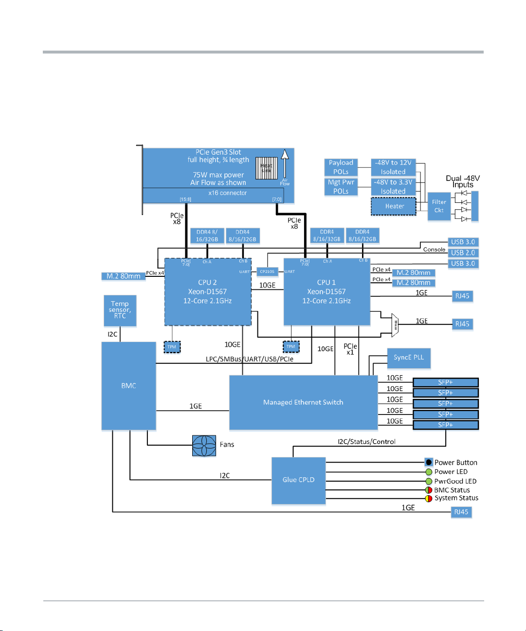
w
System Overview
1.5 Block Diagram
This following block diagram shows the major functions and interfaces of the MC1600
Extreme Edge Server.
Figure 1-4 MC1600 Extreme Edge Server - Dual CPU Block Diagram
System Overvie
52 MC1600 Extreme Edge Server Installation and Use (6806870A02B)
Page 53

1.6 Extreme Edge Server Base Board
Up to two Broadwell-DE processors are provided on the Extreme Edge Server base board.
The Broadwell-DE is a System on Chip (SoC) product manufactured in a BGA package and
integrates up to 16 cores, a memory controller, I/O block, and PCH logic. The following
figure is a high level block diagram of the Broadwell-DE SoC.
Figure 1-5 High Level Broadwell-DE Block Diagram
System Overview
The base board includes two nearly identical Broadwell-DE processor blocks. Note that the
features listed in the following chapters apply to both processors unless otherwise noted.
The minor differences between the two processors blocks are highlighted using keyword
CPU1 for the first processor and CPU2 for the second processor.
MC1600 Extreme Edge Server Installation and Use (6806870A02B) 53
Page 54

w
System Overview
1.6.1 CPU SKU Support
Many different CPU SKUs are available, having various core counts, core frequencies,
cache sizes, and performance levels. On the Extreme Edge Server, the following SKU has
been qualified in the initial product release.
Table 1-2 CPU SKU Support
System Overvie
CPU Type Cores Frequency Cache
Xeon D-1567 12 2.1GHz 18MB DDR4-2133 65W 5106814F44
1.6.2 Memory Controller
The Broadwell-DE processor offers an Integrated Memory Controller (IMC) that has a
two-channel memory interface operating in the Independent Channel Mode. Each channel
consists of 64 data and 8 ECC bits, plus address, control, and management signals.
On the Extreme Edge Server, a DDR4 memory interface is supported. DDR mode is
determined by the DDR3_4_STRAP pin strapping. Signal DDR3_4_STRAP is pulled high
to select DDR4 mode.
Dual memory channels are supported with one DIMM per channel at up to 2166 MT/s.
Single and dual rank DIMMs are supported. Supported DRAM device densities are 4Gb
and 8Gb. Signaling voltage for the DDR4 interface is 1.2V.
The extended temperature-capable DIMMs are required for extended temperature
MC1600 Extreme Edge Server SKUs.
Possible DIMM types are shown in Table 1-3, they can be ECC or non-ECC modules. The
type qualified for the initial product release is highlighted in green. These are x72 (ECCcapable) modules.
Table 1-3 ECC/Non-ECC DIMM Types
DDR4
Speed
TDP
SMART EC
Part #
DIMM Type Ranks
RDIMM 1 Rank x8 8GB
RDIMM 1 Rank x4 16GB
RDIMM 2 Rank x8 16GB
RDIMM 2 Rank x4 32GB
54 MC1600 Extreme Edge Server Installation and Use (6806870A02B)
8Gb
Chips
Qualified Module
X4B08QD8BNTDME-E-AY1 (C-temp)
X4B08QD8BNTDMW-E-AY1 (I-temp)
SMART EC
Part #
9706802B79
9706802B80
Page 55

1.6.2.1 Real Time Clock
A real-time clock circuit is implemented for each CPU. This circuit is backed up by an onboard coin cell battery. The CPUs synchronize their system time to the BMC.
1.6.2.2 Trusted Platform Module (TPM)
A TPM 1.2 compliant implementation is used on the Extreme Edge Server.
The TPM is connected to the LPC interface of the processor. The SERIRQ output of the
device is connected to the SERIRQ input of the processor.
1.7 Interfaces
1.7.1 PCI Express Interfaces
Each CPU has one x8 PCIe Gen3 interface to the x16 PCIe connector on the base board.
CPU1 has two x4 PCIe Gen3 interfaces to M.2 NVMe sockets on the base board. CPU1
also has an x1 PCIe Gen2 interface to the integrated Ethernet switch, one PCIe lane used
to connect to an Ethernet MAC/PHY, and an additional PCIe lane that connects to the BMC.
System Overview
CPU2 has one x4 PCIe Gen3 interface to a single M.2 NVMe socket.
There is a second Ethernet MAC/PHY device that can connect to CPU1 or CPU2 via a
single PCIe lane. These connections are described in more detail below.
1.7.1.1 PCI Express Gen3
The Integrated I/O (IIO) module of Broadwell-DE processor provides 24 lanes of PCIe Gen
3 interface [3], compr ising two ports. The first port (PE1) is a x16 PCIe that can be
bifurcated to two x8, two x4 and one x8, or four x4 root ports each, and the second port
(PE2) is a x8 PCIe that can be bifurcated to two x4 root ports. Refer to Figure 1-5, High
Level Broadwell-DE Block Diagram on page 53.
All PCIe Gen3 interfaces can operate as a standard PCIe root port. The processor supports
Gen1 (2.5Gb/s), Gen2 (5Gb/s) and Gen3 (8Gb/s) PCIe speeds. These speeds are
supported on all the lanes. Port bifurcation, degraded mode, lane reversal, and polarity
inversion is supported for all PCIe ports.
On the Extreme Edge Server, the x16 port (PE1) of each CPU is bifurcated into two x8
ports, of which only the first one is used. Connections to the PCIe connector are according
following table.
MC1600 Extreme Edge Server Installation and Use (6806870A02B) 55
Page 56

w
System Overview
Table 1-4 PCI Express Gen3 Interfaces to PCIe Connector
System Overvie
CPU
CPU1 PE1 <7:0> 1 <7:0> PETp/PETn<7:0> and PERp/PERn <7:0>
CPU2 PE1 <7:0> 1 <7:0>
IIO
Port
IIO Port
Lanes
On the Extreme Edge Server, the x8 port (PE2) of each CPU is bifurcated into two x4 ports.
These ports connect to the M.2 NVMe modules according to the following table.
Table 1-5 PCI Express Gen3 Interfaces to M.2 Modules
CPU IIO Port
CPU1 PE2 <3:0> 1 <3:0> M.2 (Primary)
CPU1 PE2 <7:4> 2 <3:0> M.2 (Secondary)
CPU2 PE2 <3:0> 1 <3:0> M.2
1.7.1.2 PCI Express Gen2
The Integrated PCH Logic additionally implements eight lanes of PCIe Gen2 that can be
split into eight root ports. The ports support Gen1 (2.5Gb/s) and Gen2 (5Gb/s) speeds.
Lanes 1-4 and lanes 5-8 can independently be configured as four x1, two x2, one x2 and
two x1, or one x4 port(s).
Bifurcated
Port
IIO Port
Lanes
Bifurcated
Port Lanes
Bifurcated
Port
Destination
(PCIe Connector Signals)
PETp/PETn<15:8> and PERp/PERn
<15:8>
Bifurcated Port
Lanes
Destination
On the Extreme Edge Server, lanes 1-4 of CPU1 and CPU2 are configured as four x1 ports.
These ports are connected according to the following table. Default routing of the second
MAC/PHY is to CPU2 on dual-CPU variants, and to CPU1 on single-CPU variants.
Table 1-6 PCI Express Gen2 (PCH) Interfaces
CPU
CPU1 Lanes 1-4 1 Ethernet Switch 5.0Gbps (Gen2)
CPU1 Lanes 1-4 2 Ethernet MAC/PHY A 2.5Gbps (Gen1)
CPU1 Lanes 1-4 3 Ethernet MAC/PHY B (option) 2.5Gbps (Gen1)
CPU2 Lanes 1-4 3 Ethernet MAC/PHY B (default) 2.5Gbps (Gen1)
CPU1 Lanes 1-4 4 BMC 2.5Gbps (Gen1)
56 MC1600 Extreme Edge Server Installation and Use (6806870A02B)
PCH PCIe
Port Group
Port (Lane) Destination Link Speed
Page 57

1.7.2 Ethernet Interface
Each CPU has one 10Gb Ethernet interface to the Ethernet switch. The CPUs also have
one 10Gb Ethernet interface directly between them. In addition, CPU1 has one 1Gb
Ethernet interface to a front panel RJ-45 connector. There is a second front panel RJ-45
port that can come from CPU1 or CPU2 as a build option. These are described in more
detail below.
1.7.2.1 Gigabit Ethernet Controller
The integrated Gigabit Ethernet controller is not used on CPU1 or CPU2.
1.7.2.2 PCIe-Based Gigabit Ethernet
One Ethernet MAC/PHY is connected to CPU1 via PCIe and provides a front panel
10/100/1000Base-T port, denoted ETH1 on the front panel. The second Ethernet
MAC/PHY is connected to CPU1 or CPU2 via PCIe and also goes to a front panel
10/100/1000Base-T port, denoted ETH2 on the front panel. By default, this port comes from
CPU2 on dual-CPU variants and from CPU1 on single-CPU variants.
1.7.2.3 10 Gigabit Ethernet Controller
System Overview
Broadwell-DE contains a dual port 10Gb Ethernet controller with two independent 10Gb
Ethernet MACs each having PHY device interfaces for KX4 or KR mode. The controller
supports 10Gb, 2.5Gb and 1Gb operations on its network data interface.
Port 0 of the integrated 10Gb Ethernet controller is connected to the Ethernet
switch. It uses the integrated KR PHY and is configured for 10GBASE-KR mode
(10Gbps, 1 lane).
Port 1 of the integrated 10Gb Ethernet controller is connected between the
Broadwell-DE processors. It uses the integrated KR PHY and is configured for
10GBASE-KR mode (10Gbps, 1 lane).
A single external SPI flash for Ethernet configuration is connected to each CPU.
1.7.3 SPI Interface
The Broadwell-DE processor includes a Serial Peripheral Interface (SPI) consisting of clock
(CLK), master data out (MOSI), master data in (MISO) and an active low chip select
(CS_L).
Broadwell-DE supports up to two SPI flash devices using two separate chip select pins. The
SPI device is 16MB and operates at 50MHz. A SPI flash device with a valid descriptor must
be attached to chip select 0 as the BIOS boot device.
MC1600 Extreme Edge Server Installation and Use (6806870A02B) 57
Page 58

w
System Overview
On the Extreme Edge Server, there is a second on-board BIOS SPI flash device. This
device is used to store a golden BIOS image for recovery in the event the primary BIOS
image is corrupted.
1.7.4 USB Interface
Broadwell-DE contains one eXtensible Host Controller Interface (xHCI) controller and one
Enhanced Host Controller Interface (EHCI) controller.
1.7.4.1 USB 3.0 Ports (xHCI)
For each CPU, port 1 from the xHCI controller is routed to a USB 3.0 Type A connector on
the front panel of the server.
1.7.4.2 USB 2.0 Ports (EHCI)
The EHCI controller supports up to four USB 2.0 high-speed root ports. USB 2.0 allows
data transfers up to 480Mb/s.
For each CPU, port 1 from the EHCI controller is routed to the front panel USB Type A
connector. Port 1 implements a USB 2.0 based debug port that provides support for
debugger software to interact with the CPU.
System Overvie
For CPU1 only, port 2 of the EHCI controller is routed to the BMC. For CPU2, this port is
unused. The other ports of the EHCI controller are unused.
1.7.5 UART Interface
A dual UART controller is integrated in the Broadwell-DE processor.
Serial console COM0 of each CPU is connected to a USB to Dual UART bridge device,
Silicon Labs CP2105F01-GM (5106811D61). The CP2105 includes a USB 2.0 full speed
function controller, USB transceiver, oscillator, one-time programmable ROM, and two
asynchronous serial data ports (UARTs) with full modem control signals. Because there are
two UART ports on the CP2105, one device can be shared between both CPUs. The UART
interfaces are connected to the processors and the USB port of CP2105 is connected to a
Type A USB connector on the front panel for access to the consoles of both CPUs through
a single USB connector.
The computer used to display the console information must have the CP2105 software
driver installed. Drivers for Linux or Windows are available at the Silicon Labs web site,
www.silabs.com. The CP2105 device is powered from the host cable so that the terminal
session is not lost when system power is cycled.
Serial port COM1 of each CPU is routed to the BMC through the Glue CPLD.
58 MC1600 Extreme Edge Server Installation and Use (6806870A02B)
Page 59

1.7.6 SMBus and I2C Interface
The Broadwell-DE integrates a SMBus 2.0 controller that provides an interface to manage
peripherals such as the Serial Presence Detection (SPD) on the RAM, thermal sensors,
PCI cards, etc. There are four SMBus ports on the SoC. The slave interface allows an
external microcontroller to access system resources.The diagram below shows the SMBus
architecture of each CPU.
Figure 1-6 CPU SMBus Architecture
System Overview
MC1600 Extreme Edge Server Installation and Use (6806870A02B) 59
Page 60

w
System Overview
The Host SMBus interface (SMBCLK, SMBDATA) is connected to the XDP connector and
to the point of load power controllers for VCCIN and VDDQ (IR3584 devices). It also
connects to a local accelerometer that can be used for debug of vibration related issues
(CPU1 SMBus only).
The SM Link 0 interface (SML0CLK, SML0DATA) from CPU1 is routed to the BMC. This
interface is used to read thermal sensors in the CPU and on the DIMM modules. The BMC
also uses this interface for communication with the CPU CPLD to control the card and read
status registers.
The SM Link 1 interface (SML1CLK, SML1DATA) of each CPU is not used.
The DDR I2C interface (DDR_SDA, DDR_SCL) is connected to the DIMM slots. The
interface is used to read the SPD EEPROM and the integrated thermal sensor of the DIMM
modules.
1.7.7 LPC Interface
The LPC interface of each CPU is connected to an optional TPM module.
The LPC interface of each processor is also connected to the CPU CPLD to allow Port80
post code forwarding and as a communication channel to the CPLD registers. The LPC
interface of CPU1 is also routed to the Glue CPLD for access to the status and control
registers of the SFP+ modules.
System Overvie
The LPC interface of CPU1 is also directly connected to the BMC LPC pins.
1.7.8 PECI Interface
The Platform Environment Control Interface (PECI) uses a single wire for self-clocking and
data transfer. The bus requires no additional control lines. The interface design is optimized
for interfacing to Intel processor (CPU) and chipset components (PCH) in both single
processor and multiple processor environments.
The processor PECI client is designed to support processor and DRAM thermal
management, platform manageability functions including thermal, power, and error
monitoring, as well as processor interface tuning and diagnostics capabilities.
The PECI interface is connected between CPU and PCH, both integrated in the
Broadwell-DE SoC.
60 MC1600 Extreme Edge Server Installation and Use (6806870A02B)
Page 61
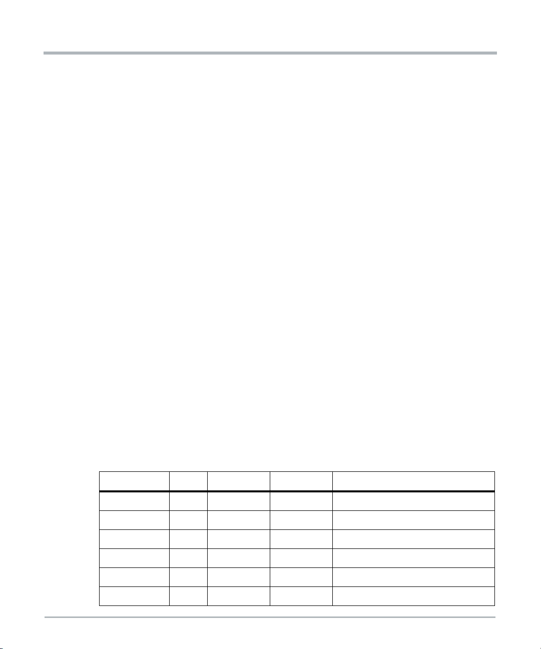
1.8 10 Gigabit Ethernet
1.8.1 Ethernet Switch
The Extreme Edge Server includes an on-board Ethernet switch, which is a 10Gbps 8-port
Ethernet switch for high-bandwidth internal and external communication. With high
performance 10Gbps SerDes, advanced Layer 2 functionality, low power, and flexible I/O
configuration, this switch is designed to reduce overall system costs. Features of the
Ethernet switch include the following:
80Gbps switching capacity bandwidth
Optional integrated ARM Cortex A9 CPU
Integrated 10G SerDes with native support for KX, KR, SFI, XFI, XAUI, RXAUI,
SGMII, QSGMII
Priority-based Flow Control (PFC)
Advanced single-stage Content Aware Engine for ACLs and QoS
Time stamping support with IEEE 1588 1-step and 2-step Transparent Clock (TC)
and Synchronized Ethernet (SyncE) as well as OAM (IEEE 802.1ag)
IEEE 802.1q VLAN and VLAN translation
Low-power Energy Efficient Ethernet (EEE) support
Enterprise-class L2/L2+ scalability
Integrated 2MB packet buffer
Nonblocking architecture, line rate at all packet sizes
Capable of being an unmanaged switch. For details contact your SMART EC sales
representative
System Overview
The following table shows the por t connections on the Ethernet switch.
Table 1-7 Ethernet Switch Port Assignments
SerDes Quad Lane Protocol Speed Destination
TSC1 0 SFI 10Gbps SFP+ Port 1 (ETH3)
TSC1 1 SFI 10Gbps SFP+ Port 2 (ETH4)
TSC1 2 SFI 10Gbps SFP+ Port 3 (ETH5)
TSC1 3 SFI 10Gbps SFP+ Port 4 (ETH6)
TSC2 0 SFI 10Gbps SFP+ Port 5 (ETH7)
TSC2 1 10G-KR 10Gbps CPU1
MC1600 Extreme Edge Server Installation and Use (6806870A02B) 61
Page 62

w
System Overview
Table 1-7 Ethernet Switch Port Assignments (continued)
SerDes Quad Lane Protocol Speed Destination
TSC2 2 SGMII 1Gbps BMC
TSC2 3 10G-KR 10Gbps CPU2
1.8.2 SFP+ Ports
The Extreme Edge Server has five SFP+ ports on the front panel, each of which is directly
connected to the Ethernet switch. The front panel cages can accept 10GBase-SR (short
range) or 10GBase-LR (long range) SFP+ modules. Higher powered modules may require
SFP+ modules with industrial temperature limits. These ports include Synchronous
Ethernet support through the Ethernet switch. The I2C bus from each SFP+ is connected
to the Glue CPLD.
1.8.3 Synchronous Ethernet and IEEE 1588 Support
1.8.3.1 Synchronous Ethernet PLL
System Overvie
The Extreme Edge Server has a Synchronous Ethernet (SyncE) PLL device on board that
allows a recovered clock from one SFP+ port to be used as the Ether net timing reference
for the Ethernet switch. This allows the other SFP+ ports to be synchronized to this timing
reference. The diagram below shows the SyncE clocking architecture.
Figure 1-7 Synchronous Ethernet Clocking Architecture
62 MC1600 Extreme Edge Server Installation and Use (6806870A02B)
Page 63

The SyncE PLL has a free-running oscillator that can be used to generate a reference clock
when no recovered clock is available. When it is desired to use a recovered clock, the ports
used for primary and secondary clock recovery can be set up in the control registers of the
Ethernet switch. The primary and secondary recovered clocks go to the input multiplexer
of the SyncE PLL. The clock valid signals go to the input selection logic of the SyncE PLL
chip. In addition, the SyncE PLL chip has internal monitoring circuits to evaluate the quality
of the incoming clocks, and it can be set up for hitless, automatic switching between the
primary and secondary recovered clocks. It also supports holdover mode in case the
recovered clocks are temporarily lost.
The SyncE PLL can store up to four configurations (0-3). By default, configuration 0 is the
only one programmed and is loaded at power-on. Other configurations (1 - 3) could be
programmed into the device and selected via a register in the Glue CPLD. Upon the next
payload reset, the selected configuration would be loaded. The Glue CPLD retains this
selection as long as management power is present.
1.8.3.2 IEEE 1588 Support
The Ethernet switch has time-stamping capability with support for IEEE 1588 1-step and
2-step transparent clock. No external hardware is required.
System Overview
1.9 PCIe Slot
The Extreme Edge Server base board has a x16 PCIe right-angle connector that can
accommodate a standard or custom PCIe add-in card up to full height, 3/4 length.
Additional physical height is available beyond 0.8" if a customer application needs
additional heat sink height.
Connector lanes are routed as:
Lane 7:0 to PCIe 3.0 port of CPU1
Lanes 15:8 to PCIe 3.0 port of CPU2
Because of this routing, a standard PCIe add-in card with a single port can only connect to
CPU1, with a maximum link width of x8.
A custom PCIe add-in card with multiple ports on the PCIe connector can connect to both
CPUs. For example, a custom card may have x16 card edge, bifurcated into two x8 ports.
In this case, it can connect to CPU1 and CPU2, each with a maximum link width of x8. Refer
to Figure 1-5, High Level Broadwell-DE Block Diagram on page 53.
MC1600 Extreme Edge Server Installation and Use (6806870A02B) 63
Page 64
w
System Overview
NOTE: Because the PCIe slot has only one reset signal, which is generated by CPU1, this
custom routing has implications when a CPU is rebooted. If both CPUs have
already established a link to the installed PCIe card and it is necessary to reboot
one CPU, then both CPUs must be rebooted simultaneously to successfully reestablish PCIe links to both CPUs. If both are not rebooted simultaneously then
one CPU may not re-establish a PCIe link.
The PCIe slot receives 12V (5.5A max) and 3.3V (3.0A max) power from the base board.
The PCIe slot can accommodate a board with up to 75W power dissipation.
1.10 Storage
The Extreme Edge Server includes three sockets for M.2 NVMe modules to provide mass
storage for the CPUs. Two of the M.2 modules are connected to CPU1 and one is
connected to CPU2. In each case they are connected via a PCIe Gen3 x4 interface to the
corresponding CPU. The sockets accept a 22mm x 80mm (2280) module with the M key.
Industrial temperature modules are required for the extended-temperature versions of the
Extreme Edge Server.
1.10.1 Supported NVMe Modules
System Overvie
The following types of M.2 NVMe modules are compatible with the Extreme Edge Server.
Only 80mm M.2 drives are supported. The types qualified in the initial product release are
highlighted in green
Table 1-8 M.2 NVMe Module Support
Capacity Size Interface Memory Type Qualified Module
AF128GSMJA-AY3 (C-
128GB 2280
256GB 2280
512GB 2280
1024GB 2280
64 MC1600 Extreme Edge Server Installation and Use (6806870A02B)
PCIe Gen3
x4
PCIe Gen3
x4
PCIe Gen3
x4
PCIe Gen3
x4
MLC NAND Flash
MLC NAND Flash
MLC NAND Flash
MLC NAND Flash
temp)
AF128GSMJA-AY2 (Itemp)
SMART EC
Part #
8806813A29
8806813A26
Page 65

1.11 Connectors
1.11.1 PCI Express Connector
The pinout of x16 PCI Express edge connector is as defined in the PCI Express Card
Electromechanical Specification Revision 3.0 with the exception that PCIe lanes [15:8] are
defined as a second PCIe link, lanes [7:0] respectively. On the base board, these are routed
to CPU2 as previously noted in this document.
Table 1-9 PCIe Slot Connector Pinout
Pin Function Pin Function
A1 PRSNT1# - Card Presence Detect B1 12V Power
A2 12V Power B2 12V Power
A3 12V Power B3 12V Power
A4 Ground B4 Ground
A5 JTAG TCK - Input to Card B5 SMCLK
A6 JTAG TDI - Input to Card B6 SMDAT
System Overview
A7 JTAG TDO - Output from Card B7 Ground
A8 JTAG TMS - Input to Card B8 3.3V Power
A9 3.3V Power B9 JTAG TRST# - Input to Card
A10 3.3V Power B10 3.3V Aux Power
A11 PERST# - Reset to Card B11 NC
A12 Ground B12 NC
A13 100MHz Refclk+ B13 Ground
A14 100MHz Refclk- B14 PETp0 - Lane 0 from CPU1 to Card
A15 Ground B15 PETn0 - Lane 0 from CPU1 to Card
A16 PERp0 - Lane 0 from Card to CPU1 B16 Ground
A17 PERn0 - Lane 0 from Card to CPU1 B17 PRSNT2# - Card Presence Detect
A18 Ground B18 Ground
A19 NC B19 PETp1 - Lane 1 from CPU1 to Card
A20 Ground B20 PETn1 - Lane 1 from CPU1 to Card
MC1600 Extreme Edge Server Installation and Use (6806870A02B) 65
Page 66

w
System Overview
Table 1-9 PCIe Slot Connector Pinout (continued)
Pin Function Pin Function
A21 PERp1 - Lane 1 from Card to CPU1 B21 Ground
A22 PERn1 - Lane 1 from Card to CPU1 B22 Ground
A23 Ground B23 PETp2 - Lane 2 from CPU1 to Card
A24 Ground B24 PETn2 - Lane 2 from CPU1 to Card
A25 PERp2 - Lane 2 from Card to CPU1 B25 Ground
A26 PERn2 - Lane 2 from Card to CPU1 B26 Ground
A27 Ground B27 PETp3 - Lane 3 from CPU1 to Card
A28 Ground B28 PETn3 - Lane 3 from CPU1 to Card
A29 PERp3 - Lane 3 from Card to CPU1 B29 Ground
A30 PERn3 - Lane 3 from Card to CPU1 B30 NC
A31 Ground B31 PRSNT2# - Card Presence Detect
A32 NC B32 Ground
System Overvie
A33 NC B33 PETp4 - Lane 4 from CPU1 to Card
A34 Ground B34 PETn4 - Lane 4 from CPU1 to Card
A35 PERp4 - Lane 4 from Card to CPU1 B35 Ground
A36 PERn4 - Lane 4 from Card to CPU1 B36 Ground
A37 Ground B37 PETp5 - Lane 5 from CPU1 to Card
A38 Ground B38 PETn5 - Lane 5 from CPU1 to Card
A39 PERp5 - Lane 5 from Card to CPU1 B39 Ground
A40 PERn5 - Lane 5 from Card to CPU1 B40 Ground
A41 Ground B41 PETp6 - Lane 6 from CPU1 to Card
A42 Ground B42 PETn6 - Lane 6 from CPU1 to Card
A43 PERp6 - Lane 6 from Card to CPU1 B43 Ground
A44 PERn6 - Lane 6 from Card to CPU1 B44 Ground
A45 Ground B45 PETp7 - Lane 7 from CPU1 to Card
A46 Ground B46 PETn7 - Lane 7 from CPU1 to Card
66 MC1600 Extreme Edge Server Installation and Use (6806870A02B)
Page 67

System Overview
Table 1-9 PCIe Slot Connector Pinout (continued)
Pin Function Pin Function
A47 PERp7 - Lane 7 from Card to CPU1 B47 Ground
A48 PERn7 - Lane 7 from Card to CPU1 B48 PRSNT2# - Card Presence Detect
A49 Ground B49 Ground
A50 NC B50 PETp8 - Lane 0 from CPU2 to Card
A51 Ground B51 PETn8 - Lane 0 from CPU2 to Card
A52 PERp8 - Lane 0 from Card to CPU2 B52 Ground
A53 PERn8 - Lane 0 from Card to CPU2 B53 Ground
A54 Ground B54 PETp9 - Lane 1 from CPU2 to Card
A55 Ground B55 PETn9 - Lane 1 from CPU2 to Card
A56 PERp9 - Lane 1 from Card to CPU2 B56 Ground
A57 PERn9 - Lane 1 from Card to CPU2 B57 Ground
A58 Ground B58 PETp10 - Lane 2 from CPU2 to Card
A59 Ground B59 PETn10 - Lane 2 from CPU2 to Card
A60 PERp10 - Lane 2 from Card to CPU2 B60 Ground
A61 PERn10 - Lane 2 from Card to CPU2 B61 Ground
A62 Ground B62 PETp11 - Lane 3 from CPU2 to Card
A63 Ground B63 PETn11 - Lane 3 from CPU2 to Card
A64 PERp11 - Lane 3 from Card to CPU2 B64 Ground
A65 PERn11 - Lane 3 from Card to CPU2 B65 Ground
A66 Ground B66 PETp12 - Lane 4 from CPU2 to Card
A67 Ground B67 PETn12 - Lane 4 from CPU2 to Card
A68 PERp12 - Lane 4 from Card to CPU2 B68 Ground
A69 PERn12 - Lane 4 from Card to CPU2 B69 Ground
A70 Ground B70 PETp13 - Lane 5 from CPU2 to Card
A71 Ground B71 PETn13 - Lane 5 from CPU2 to Card
A72 PERp13 - Lane 5 from Card to CPU2 B72 Ground
MC1600 Extreme Edge Server Installation and Use (6806870A02B) 67
Page 68

w
System Overview
Table 1-9 PCIe Slot Connector Pinout (continued)
Pin Function Pin Function
A73 PERn13 - Lane 5 from Card to CPU2 B73 Ground
A74 Ground B74 PETp14 - Lane 6 from CPU2 to Card
A75 Ground B75 PETn14 - Lane 6 from CPU2 to Card
A76 PERp14 - Lane 6 from Card to CPU2 B76 Ground
A77 PERn14 - Lane 6 from Card to CPU2 B77 Ground
A78 Ground B78 PETp15 - Lane 7 from CPU2 to Card
A79 Ground B79 PETn15 - Lane 7 from CPU2 to Card
A80 PERp15 - Lane 7 from Card to CPU2 B80 Ground
A81 PERn15 - Lane 7 from Card to CPU2 B81 PRSNT2# - Card Presence Detect
A82 Ground B82 NC
1.11.2 -48V Power Connector
System Overvie
The input power connector is Molex 42820-2213 (2806858A05). The pinout of each power
connector is as shown.
Table 1-10 Input Power Connector Pinout
Pin Function
1 -48V RTN (+ input)
2 -48V (- input)
68 MC1600 Extreme Edge Server Installation and Use (6806870A02B)
Page 69

1.11.3 SFP+ Module Connectors
Table 1-11 SFP+ Connector Pinout
Pin Function Pin Function
1 GND 11 GND
2 TX_FAULT 12 RX-
3 TX_DISABLE 13 RX+
4 SDA 14 GND
5 SCL 15 +3.3V
6 MOD_ABS 16 +3.3V
7 RS0 17 GND
8 RX_LOS 18 TX+
9 RS1 19 TX-
10 GND 20 GND
System Overview
1.11.4 RJ-45 Ethernet Connectors
Table 1-12 Ethernet RJ-45 Connector Pinout
Pin Function - 10Base-T or 100Base-Tx Function - 1000Base-T
1 ETH_TX+ ETH_DA+
2 ETH_TX- ETH_DA-
3 ETH_RX+ ETH_DB+
4 ETH_DC+
5 ETH_DC-
6 ETH_RX- ETH_DB-
7 ETH_DD+
8 ETH_DD-
MC1600 Extreme Edge Server Installation and Use (6806870A02B) 69
Page 70

w
System Overview
1.11.5 USB 2.0 Connector
Table 1-13 USB 2.0 Connector Pinout
Pin Function
1VBUS
2D-
3D+
4 GND
1.11.6 USB 3.0 Connectors
Table 1-14 USB 3.0 Connector Pinout
Pin Function
1VBUS
2D-
3D+
System Overvie
4 GND
5 SS_RX-
6 SS_RX+
7 GND
8 SS_TX-
9 SS_TX+
1.11.7 DDR4 DIMM Connectors
Table 1-15 DDR4 DIMM Pinout
Pin Signal Pin Signal Pin Signal Pin Signal
1 nc 73 VDDQ 145 nc 217 VDDQ
2 GND 74 CK0 146 VREF 218 CK1
3 DQ4 75 CK0# 147 GND 219 CK1#
4 GND 76 VDDQ 148 DQ5 220 VDDQ
70 MC1600 Extreme Edge Server Installation and Use (6806870A02B)
Page 71

System Overview
Table 1-15 DDR4 DIMM Pinout (continued)
Pin Signal Pin Signal Pin Signal Pin Signal
5 DQ0 77 VTT 149 GND 221 VTT
6 GND 78 EVENT# 150 DQ1 222 PAR
7 DQS9 79 MA0 151 GND 223 VDDQ
8 DQS9# 80 VDDQ 152 DQS0# 224 BA1
9 GND 81 BA0 153 DQS0 225 MA10
10 DQ6 82 MA16 154 GND 226 VDDQ
11 GND 83 VDDQ 155 DQ7 227 nc
12 DQ2 84 CS0# 156 GND 228 MA14
13 GND 85 VDDQ 157 DQ3 229 VDDQ
14 DQ12 86 MA15 158 GND 230 nc
15 GND 87 ODT0 159 DQ13 231 VDDQ
16 DQ8 88 VDDQ 160 GND 232 MA13
17 GND 89 CS1# 161 DQ9 233 VDDQ
18 DQS10 90 VDDQ 162 GND 234 nc
19 DQS10# 91 ODT1 163 DQS1# 235 nc
20 GND 92 VDDQ 164 DQS1 236 VDDQ
21 DQ14 93 nc 165 GND 237 nc
22 GND 94 GND 166 DQ15 238 SA2
23 DQ10 95 DQ36 167 GND 239 GND
24 GND 96 GND 168 DQ11 240 DQ37
25 DQ20 97 DQ32 169 GND 241 GND
26 GND 98 GND 170 DQ21 242 DQ33
27 DQ16 99 DQS13 171 GND 243 GND
28 GND 100 DQS13# 172 DQ17 244 DQS4#
29 DQS11 101 GND 173 GND 245 DQS4
30 DQS11# 102 DQ38 174 DQS2# 246 GND
MC1600 Extreme Edge Server Installation and Use (6806870A02B) 71
Page 72

w
System Overview
Table 1-15 DDR4 DIMM Pinout (continued)
Pin Signal Pin Signal Pin Signal Pin Signal
31 GND 103 GND 175 DQS2 247 DQ39
32 DQ22 104 DQ34 176 GND 248 GND
33 GND 105 GND 177 DQ23 249 DQ35
34 DQ18 106 DQ44 178 GND 250 GND
35 GND 107 GND 179 DQ19 251 DQ45
36 DQ28 108 DQ40 180 GND 252 GND
37 GND 109 GND 181 DQ29 253 DQ41
38 DQ24 110 DQS14 182 GND 254 GND
39 GND 111 DQS14# 183 DQ25 255 DQS5#
40 DQS12 112 GND 184 GND 256 DQS5
41 DQS12# 113 DQ46 185 DQS3# 257 GND
42 GND 114 GND 186 DQS3 258 DQ47
System Overvie
43 DQ30 115 DQ42 187 GND 259 GND
44 GND 116 GND 188 DQ31 260 DQ43
45 DQ26 117 DQ52 189 GND 261 GND
46 GND 118 GND 190 DQ27 262 DQ53
47 ECC4 119 DQ48 191 GND 263 GND
48 GND 120 GND 192 ECC5 264 DQ49
49 ECC0 121 DQS15 193 GND 265 GND
50 GND 122 DQS15# 194 ECC1 266 DQS6#
51 DQS17 123 GND 195 GND 267 DQS6
52 DQS17# 124 DQ54 196 DQS8# 268 GND
53 GND 125 GND 197 DQS8 269 DQ55
54 ECC6 126 DQ50 198 GND 270 GND
55 GND 127 GND 199 ECC7 271 DQ51
56 ECC2 128 DQ60 200 GND 272 GND
72 MC1600 Extreme Edge Server Installation and Use (6806870A02B)
Page 73

System Overview
Table 1-15 DDR4 DIMM Pinout (continued)
Pin Signal Pin Signal Pin Signal Pin Signal
57 GND 129 GND 201 ECC3 273 DQ61
58 RESET# 130 DQ56 202 GND 274 GND
59 VDDQ 131 GND 203 CKE1 275 DQ57
60 CKE0 132 DQS16 204 VDDQ 276 GND
61 VDDQ 133 DQS16# 205 nc 277 DQS7#
62 ACT# 134 GND 206 VDDQ 278 DQS7
63 BG0 135 DQ62 207 BG1 279 GND
64 VDDQ 136 GND 208 ALERT# 280 DQ63
65 MA12 137 DQ58 209 VDDQ 281 GND
66 MA9 138 GND 210 MA11 282 DQ59
67 VDDQ 139 SA0 211 MA7 283 GND
68 MA8 140 SA1 212 VDDQ 284 VDDSPD
69 MA6 141 SCL 213 MA5 285 SDA
70 VDDQ 142 VPP 214 MA4 286 VPP
71 MA3 143 VPP 215 VDDQ 287 VPP
72 MA1 144 nc 216 MA2 288 VPP
MC1600 Extreme Edge Server Installation and Use (6806870A02B) 73
Page 74

w
System Overview
1.11.8 NVMe Module Connectors
Table 1-16 NVMe Module Pinout
Pin Function Pin Function
1 GND 2 +3.3V
3 GND 4 +3.3V
5 PERn3 - Output from Module 6 nc
7 PERp3 - Output from Module 8 nc
9 GND 10 Activity LED
11 PETn3 - Input to Module 12 +3.3V
13 PETp3 - Input to Module 14 +3.3V
15 GND 16 +3.3V
17 PERn2 - Output from Module 18 +3.3V
19 PERp2 - Output from Module 20 nc
21 GND 22 nc
System Overvie
23 PETn2 - Input to Module 24 nc
25 PETp2 - Input to Module 26 nc
27 GND 28 nc
29 PERn1 - Output from Module 30 nc
31 PERp1 - Output from Module 32 nc
33 GND 34 nc
35 PETn1 - Input to Module 36 nc
37 PETp1 - Input to Module 38 nc
39 GND 40 SMB_CLK
41 PERn0 - Output from Module 42 SMB_DATA
43 PERp0 - Output from Module 44 ALERT#
45 GND 46 nc
47 PETn0 - Input to Module 48 nc
49 PETp0 - Input to Module 50 PERST#
74 MC1600 Extreme Edge Server Installation and Use (6806870A02B)
Page 75

System Overview
Table 1-16 NVMe Module Pinout (continued)
Pin Function Pin Function
51 GND 52 nc
53 100MHz Refclk- 54 nc
55 100MHz Refclk+ 56 nc
57 GND 58 nc
59 Key 60 Key
61 Key 62 Key
63 Key 64 Key
65 Key 66 Key
67 nc 68 Susclk
69 nc 70 +3.3V
71 GND 72 +3.3V
73 GND 74 +3.3V
75 GND
MC1600 Extreme Edge Server Installation and Use (6806870A02B) 75
Page 76
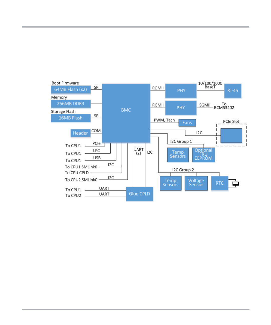
w
System Overview
1.12 Baseboard Management Controller (BMC)
The Extreme Edge Server includes a Baseboard Management Controller (BMC) to perform
system management functions. The device used as the BMC is a highly-integrated SoC
management processor. A block diagram of the BMC subsystem is shown next.
Figure 1-8 BMC Block Diagram
System Overvie
1.12.1 BMC Subsystem Devices
BMC Core
– 457-ball FPBGA package, 23mm x23mm2, 0.8mm ball pitch
Memory/Flash/EEPROM
– Memory: 256MB, DDR3
– Flash: Dual 64MB, main socket and backup device soldered
– Storage flash: 16MB
Ethernet PHY
– RGMII to SGMII conversion going to Ethernet switch
– RGMII to 10/100/1000Base-T going to front panel RJ-45
76 MC1600 Extreme Edge Server Installation and Use (6806870A02B)
Page 77

System Overview
RTC: I
Reset Generator
2
C RTC w/128Byte EEPROM, 64Bytes SRAM, UID
1.12.2 BMC Subsystem Features
Platform Power Management
– Enable/disable -48V to 12V payload power brick (via Glue CPLD)
– Power up/down or reset individual CPUs (via CPU CPLD)
FRU Management
– Provides platform FRU information
External Connectivity
– 10/100/1000BaseT connectivity (RJ-45) for management access
Platform Control and Status
– PERST_N control for PCIe slot
– Power button signal
– Power LED (signifies -48V is present)
– PwrGood LED (signifies payload power present and good)
– BMC Status LED
Private I
– 6x temperature sensors
– 2x voltage sensors
– Real time clock
Additional GPIO
– Fan control: 3x PWM out, 7x tachometer in with noise filter
– Analog voltage sensing for critical voltages
BMC Debug Options
– 8x debug LED (green), 1x heartbeat LED (red)
– 4x debug switch (DIP switch type)
– Console output via 3-pin header, R-232
PCIe
– PCIe GEN1 x1 link (endpoint) to CPU1 (root)
2
C Buses
MC1600 Extreme Edge Server Installation and Use (6806870A02B) 77
Page 78
w
System Overview
1.12.3 BMC Private I2C Buses
The two private I2C buses of the BMC, which are directly connected to the BMC, include
discrete temperature sensors, voltage sensors, an RTC, and an optional FRU EEPROM.
There are also routing resistors on the board that allow connection of these buses to the
Glue CPLD as a BOM option. The I
tables.
Table 1-17 BMC I2C Bus 8 Devices
7-bit Addr 8-bit Addr Description
0x49 0x92 Temperature sensor
0x4A 0x94 Temperature sensor
0x4B 0x96 Temperature sensor
0x4C 0x98 Temperature sensor
0x50 0xA0 Optional FRU EEPROM (BOM option)
Table 1-18 BMC I2C Bus 7 Devices
7-bit Addr 8-bit Addr Description
System Overvie
2
C addresses of the devices are shown in the following
0x48 0x90 Voltage sensor for CPU1
0x4A 0x94 Voltage sensor for CPU2
0x4D 0x9A Temperature sensor
0x4E 0x9C Temperature sensor
0x57 0xAE EEPROM
0x6F 0xDE RTC EEPROM
1.13 Programmable Logic
Two Programmable Logic Device (CPLD) are provided for various functions such as power
up control, CPU interface multiplexing, SMBus routing, and additional glue logic functions
needed on the card.
1.13.1 CPU CPLD
The CPU CPLD on the Extreme Edge Server runs off payload power and is associated with
the two CPU complexes. It implements these major functions:
78 MC1600 Extreme Edge Server Installation and Use (6806870A02B)
Page 79

Enable all on-board DC-DC converter for CPU complexes
Implementation of power-up timing sequence requirements
Supervision of power rails for CPU complex
2
I
C slave interface connected the BMC
– Power control of both CPUs
– Power fail registers for both CPUs
– Control and status registers for each CPU
– Error status registers for each CPU
LPC target interface for each CPU
– Port 0x80 for each CPU, select CPU via SMBus register
– SERIRQ for KCS interr upt support
– Control and status registers
– Can be used to update configuration of the logic device
1.13.2 Glue CPLD
System Overview
The Glue CPLD on the Extreme Edge Server runs off management power and is
associated with the BMC and is powered anytime -48V power is present. It implements
these major functions:
Monitor output of low-temperature thermal switch
Enable BMC power under appropriate operating conditions
Implement power-up timing sequence requirements for non-CPU power rails
Supervision of non-CPU power rails
Enable on-board clocks when payload power is stable
2
I
C slave interface connected the BMC
Update configuration of the logic device via I
Reset control
BMC serial routing, routes 1 UART from each CPU to BMC
Control debug LEDs via registers
Watchdog timer
LPC slave interface connected to CPU1
Implement status and control registers for SFP+ modules
2
C interface
MC1600 Extreme Edge Server Installation and Use (6806870A02B) 79
Page 80

w
System Overview
1.14 Power Supply
1.14.1 Power Architecture
The figure below illustrates the high-level power architecture of the Extreme Edge Server.
When -48V power is applied the management power brick is enabled, which generates
3.3V to run the management circuits. At low temperatures, the heater is enabled. Once the
BMC has booted it waits for the power button to be pressed, after which it enables the
payload power POL converters and kicks off the CPU boot process. There is also an autopower-on mode where the BMC does not wait for the power button, but automatically
powers up the payload instead.
Figure 1-9 Power Architecture
System Overvie
1.14.2 Payload Power-Up Sequence
When the power button is pressed, the 12V power rail is enabled and the 3.3V and 5V
standby power supplies automatically start up. The ME Engine and the CPU CPLD are
powered at this point.
The next step of the power-up sequence is initiated via a message from the BMC to the
CPU CPLD. This requires a connection between the BMC and the CPU CPLD/ME via
SMBus. The CPU CPLD implements registers for power up control. When a message to
power one of the CPUs is sent by the BMC via SMBus to these power control registers, the
CPU power-up sequence is initiated. The power-up sequence continues until the S0 state
is reached.
The processors on the card can be powered up/down independently. This requires a dual
power-up state machine design in the CPU CPLD.
80 MC1600 Extreme Edge Server Installation and Use (6806870A02B)
Page 81

1.14.3 -48V Power Domain
The Extreme Edge Server accepts dual (redundant) -48V power inputs with a normal
operating range of -40V to -57V. This voltage range is considered Safety Extra Low Voltage
(SELV). The inputs are ORed together so that the system can run off either one. In addition,
there is an input filter to reduce conducted emissions.
Two isolated power bricks convert the -48V power to the logic domain. One is a 600W
quarter-brick that converts -48V to 12V as an intermediate bus voltage for the payload Point
of Load (POL) converters. The other is a 10W module that converts -48V to 3.3V as
management power for the BMC and Glue CPLD.
1.14.3.1 Heater Circuit
The Extreme Edge Server includes an optional heater circuit that can extend the operating
temperature range of the product down to -40°C. The heater control circuit is autonomous.
The Extreme Edge Server is required to be installed inside a closed, weather protected
location. For installation sites outside of a building, a sealed cabinet is recommended. For
cold weather start-up, wind conditions may overwhelm the server's designed-in heating
elements. In locations where cold airflow is present, the customer may be required to
provide additional heating to the cabinet.
The heater control circuit continuously monitors the heat sink temperature to make sure it
is within the operating temperature range. If it ever approaches the lower operating
temperature limit, the heater turns on again to keep sensitive devices within their operating
temperature range.
System Overview
1.15 Clock Structure
1.15.1 Processor Clocks
The Broadwell-DE SoC implements Full Integrated Clocking mode as the platform clock
architecture. In the Full Integrated Clocking mode, a 25MHz crystal oscillator provides the
input clock to the SoC which then internally generates the output clocks that are required
by all the platform components.
1.15.2 Other Clocks
The 156MHz clock for the Ethernet switch is provided by the SyncE PLL as described
previously in this document.
MC1600 Extreme Edge Server Installation and Use (6806870A02B) 81
Page 82

w
System Overview
1.16 Reset Structure
The platform supports two types of reset, namely cold reset and warm reset. Cold reset is
the first time when the platform asserts PWRGOOD_CPU and asserts RESET_CPU_N to
the core. Warm reset is typically a platform wide event and is indicated by assertion and
deassertion of the RESET_CPU_N signal on the socket while PWRGOOD_CPU remains
asserted.
1.17 Debugging Support
1.17.1 POST Code Indicators
The Broadwell-DE processor provides its BIOS POST codes via the LPC interface, which
are then decoded by the CPU CPLD. A POST code indicator is provided using discrete
LEDs placed on the PCB.
1.17.2 Dip Switches
The board includes several DIP switches for factory use. All DIP switches should stay in
their OFF positions (default).
System Overvie
1.18 Ordering and Support Information
The data sheet for the MC1600 Extreme Edge Server contain a complete list of available
product variants and accessories. Refer to the Appendix A, Related Documentation or
consult your local SMART Embedded Computing sales representative for the availability of
other variants.
For technical assistance, documentation, or to report product damage or shortages,
contact your local SMART EC sales representative or visit
https://www.smartembedded.com/ec/support/.
82 MC1600 Extreme Edge Server Installation and Use (6806870A02B)
Page 83

Site Preparation
2.1 Introduction
This chapter provides information on unpacking the MC1600 Extreme Edge Server, safety
precautions, and requirements for the product. Included are the environmental and power
requirements, mounting options, cooling considerations, acoustic noise control, and
dimensions and weight of the product.
2.2 Unpacking the Extreme Edge Server
Make sure you receive all items of your shipment:
One MC1600 Extreme Edge Server with PCIe filler plate
One Extreme Edge Server connector kit: two DC connectors and four crimp
terminals
1. Carefully inspect the server and all shipped components.
2. Request an RMA for product return at https://www.smartembedded.com/ec/support/ if
any damage or discrepancies are observed with the items.
3. Tighten loose screws before proceeding.
4. Remove the desiccant bags delivered together with the system and dispose according
to your country’s legislation.
Chapter 2
When installing or servicing the system or accessories, strictly observe the safety
precautions noted in this document. Otherwise, personal injury or property damage
may occur. Ignoring these instructions can void the system warranty.
Attach an ESD-preventive wrist strap before operating the product. Both terminals
of the wrist strap must contact well. One terminal touches bare skin and the terminal
with the alligator clip attaches to the grounding lug at I/O panel of the system.
2.3 Prepare the Installation Site
This section provides the basic site planning and installation requirements.
440W power should be available for the MC1600 system
System should be positioned so that a power source is easy to reach
Sufficient space should be available in racks to install the system
MC1600 Extreme Edge Server Installation and Use (6806870A02B) 83
Page 84

Site Preparation
Suitable equipment should be available to lift the system into the rack
Enough space should be available to run a system console terminal
Cable should be long enough to reach the system
Make sure the inlet and outlet of the Extreme Edge Server is not blocked
System should be installed in a restricted access location
System should have access by trained personnel only
Make sure that all defined environmental and power requirements are met. Refer to
Electromechanical on page 86 and Environmental on page 86.
2.3.1 Power Requirements
Make sure that a suitable -40 to -57VDC power source is within reach of the system. Two
independent power feeds can be connected to the system.
Table 2-1 System Power Requirements
Feature Value
Voltage and input current
Site Preparation
Voltage:
-40 to -57VDC (SELV)
Current:
1x11A maximum
Chassis idle power 170W
Chassis maximum power 440W
When installing additional blades or modules, make sure that the power consumption of all
installed modules does not exceed the system's maximum power dissipation.
2.3.2 Dimensions and Weight
The table below lists the dimensions and weight of the Extreme Edge Ser ver with system
components installed.
Table 2-2 Dimensions and Weight of System
Component Dimensions W x H x D Weight
Server including DIMMs, M.2 SSDs,
mounting ears, and PCIe filler panel
84 MC1600 Extreme Edge Server Installation and Use (6806870A02B)
1U (H) x 19” (W) x 12” (D)
(44.5mm x 482.6mm x 304.8mm)
12.4 lbs
(5.6 kg)
Page 85

2.4 ESD Prevention
To minimize the damage to the product pay attention to the following points:
Before touching the card or electronic components make sure that you are working
in an ESD safe environment
Attach an ESD-preventive wrist strap before operating the product. Both terminals
of the wrist strap must contact well. One terminal touches bare skin and the
terminal with the alligator clip attaches to the grounding lug at I/O panel of the
system.
Avoid moving as much as possible. Movement gathers static electricity around you
Do not touch the solder point, pin, or bare circuit
Do not leave the product in an area where others can operate it
Install the product right after you take it out of the anti-static package. If you need
to lay down the product, replace it into the anti-static package. Do not place the
product on the shelf or cabinet.
Monitor the temperature and humidity of the equipment room. Warm air decreases
the humidity but increases the static electricity in the room.
Site Preparation
2.5 Mounting Options
The Extreme Edge Server is designed for installation in an IP55/IP65 19" outdoor cabinet
or a standard 19" rack and is compliant to an IP20 Ingress Protection Rating.
The Extreme Edge Server is required to be installed inside a closed, weather protected
location. For installation sites outside of a building, a sealed cabinet is recommended. For
cold weather start-up, wind conditions may overwhelm the server’s designed-in heating
elements. In locations where cold airflow is present and where the input voltage is below
nominal, the customer may be required to provide additional heating to the cabinet.
When installing the system, you must allow for 50mm (2 inches) on each side of the server
for proper airflow.
Personal or System Damage
Unstable system installation in a rack can cause the rack to tip over. If your system
is the only one in the rack, make sure to mount the system in the lowest part of the
rack. If other systems are installed in one rack, start with the heaviest component at
the bottom.
If the rack is equipped with stabilizing devices, make sure that they are installed and
extended so that the rack is secure.Then proceed to mount or service the system.
MC1600 Extreme Edge Server Installation and Use (6806870A02B) 85
Page 86

Site Preparation
During the course of handling, shipping, and assembly, the pins, shrouds and
mounting screws, fans and other items can become loose or damaged.
Do not operate a damaged shelf, this can cause damage to installed devices.
Grounding
To ensure the system is properly grounded, each of the system's parts must contact
the EMI gasket. The system contains gaskets at the shelf and module level.
The shelf is also fitted with ESD contacts. Make sure the operator uses proper ESD
protection.
2.6 Electromechanical
Dual (redundant) -48V power input connections
High-efficiency fans in N+1 configuration with temperature sensor-based
tachometer control
Mechanical dimensions: 1U (H) x 19” (W) x 12” (D)
(44.5mm x 482.6mm x 304.8mm)
Site Preparation
NOTICE
2.7 Environmental
2.7.1 Environmental Conditions
To ensure proper function, do not operate equipment outside of the specified operating
environment.
Proper operation requires adherence to environmental conditions for deployed systems.
This includes adherence to environmental conditions when SMART EC or third-party
system components are integrated at an installation site. The Extreme Edge Server is
designed to operate under the following environmental conditions.
Table 2-3 Environmental Conditions
Characteristic Condition
0
Operating temperature
Storage temperature -40
86 MC1600 Extreme Edge Server Installation and Use (6806870A02B)
Cto65C without optional heater
Cto+65C with heater* (at the air inlet)
-40
Cto+70C
Page 87

Table 2-3 Environmental Conditions (continued)
Characteristic Condition
Humidity range 5% to 95% noncondensing
Site Preparation
Operating Altitude
Operating Vibration GR-3108-CORE Class 2 vibration
-60m to 1800m without temperature derating, up to 4000m with
temperature derating of 1C per 300m above 1800m
The Extreme Edge Server is designed for installation in an IP55/IP65 19" outdoor cabinet
and is compliant to an IP20 Ingress Protection Rating.
External air filter ing may be needed if installed in a location other than an IP55/IP65
cabinet.
2.7.2 Electronic Waste Disposal
Alway dispose used blades, system components, and batteries according to your country’s
legislation and manufacturer’s instructions.
2.8 Regulatory Compliance
The Extreme Edge Server complies with the following standards:
Table 2-4 Regulatory Standards
Standard Description
ULCSA 60950-1
EN 60950-1
IEC 60950-1 CB Scheme
Safety requirements
Directive (EU) 2015/863
(amending Annex II to Directive
2011/65/EU)
EN 55032 Class A (EU)
EN 55024 (EU)
FCC 47 CFR Part 15 Subpart B (US), Class
A
ETSI EN 300 386 Class A
Telcordia GR-1089-CORE
MC1600 Extreme Edge Server Installation and Use (6806870A02B) 87
Directive on the restriction of the use of certain
hazardous substances in electrical and electronic
equipment (RoHS)
EMC requirements
Electromagnetic Compatibility and Electrical
Safety-Generic Criteria for Network
Telecommunications Equipment, Issue 6
Page 88

Site Preparation
Figure 2-1 Location of Regulatory Labels
Site Preparation
88 MC1600 Extreme Edge Server Installation and Use (6806870A02B)
Page 89

FRU Installation
3.1 Introduction
This chapter describes the installation and removal of PCIe cards and details of the
SFP/SFP+ modules.
3.2 Install PCIe Card
The system ships with a filler card or filler panel installed into the unpopulated PCIe
slot. Remove the filler card or panel before installing PCIe card.
NOTE: The installation and removal procedures of PCIe cards depend on the type of the
card. Refer to the documentation of the respective PCIe card for these procedures.
The Extreme Edge Server card has a x16 PCIe right-angle connector that can
accommodate a standard or custom PCIe add-in card. There are two stand-offs available
for optional, custom rear support for the PCIe card. The maximum physical size is
full-height, 3/4 length.
Chapter 3
Installation Procedure
1. Make sure that the system is powered down and disconnected from DC power before
installing the card.
2. Make sure your are wearing an ESD wrist strap.
3. Remove the screws (on three sides) of the chassis top cover and remove the cover.
4. Unscrew the PCIe slot cover.
Keep the screw and store the slot cover for later use.
5. Align the PCIe card with the PCIe connector and front panel opening.
6. Press the PCIe card into the connector until it is fully seated.
7. Secure the PCIe front panel with the screw removed in step 4.
NOTES:SMART EC highly recommends securing the PCIe card to the two stand-offs
located on the chassis at the rear of the card. Custom brackets may be required.
The PCIe slot receives 12V (5.5A max) and 3.3 V (3.0A max) power from
the card. The PCIe slot can accommodate cards with up to 75W power
dissipation.
MC1600 Extreme Edge Server Installation and Use (6806870A02B) 89
Page 90

FRU Installation
The Extreme Edge Server is designed for side-to-side airflow. The PCIe
card needs to be designed similarly. PCIe boards designed for the
traditional airflow direction may cause overheating of the PCIe card or
Extreme Edge Server.
3.3 SFP/SFP+ Modules
The five SFP+ ports on the front panel can accept SFP+ (10G) or SFP (1G) modules.
Limited testing has been done with 10GBase-SR and 10GBase-LR optical modules as well
as direct-attach copper cables. High powered optics may need to be rated to industrial
temperatures. The following is a list of modules that have been verified to work in limited
testing, but most other commercially available modules should work as well.
Molex 74752-1051 (SFP+, direct attach copper, 0.5m)
Molex 74752-2301 (SFP+, direct attach copper, 3m)
Tyco 2032237-6 (SFP+, direct attach copper, 5m)
Broadcom/Avago ABCU-5700RZ (SFP, 1000Base-T)
Finisar FTLX1471D3BCL (SFP+, 10GBase-LR)
Finisar FTLX1471D3BCV (SFP+, dual-rate 1G/10GBase-SR)
Finisar FTLX8571D3BCL (SFP+, 10GBase-SR)
FRU Installation
Refer to the documentation for your specific SFP+ module for installation instructions.
90 MC1600 Extreme Edge Server Installation and Use (6806870A02B)
Page 91
System Installation
4.1 Introduction
This chapter provides instructions for installing and removing the Extreme Edge Server in
a rack or cabinet. It also provides information and procedures for grounding, powering up
and down, and disconnecting the server from the power feed.
4.2 Before Installation
Refer to Figure 1-1 on page 49 for location of LEDs, connectors and earth ground point.
Before you start the installation, make sure that you have all of the necessary equipment
and tools available.
Usage Equipment and Tools
Chapter 4
General
Server / Rack / Cabinet Four bolts or screws 6mm / 0.24" diameter
Grounding Ground cable 1.25 mm
Power DC power cable
System Access
Provide the following cables:
Earth grounding cable with an M4 ring lug in case of rack installation
Twisted pair Ethernet cable for connecting the BMC ETH
Twisted pair Ethernet cable for the front panel ETH1 and ETH2 RJ-45 ports
SFP+ or SFP modules or direct connect copper cables for the five SFP+ ports
The connectivity of the RJ-45 ports to CPU1 and/or CPU2 is covered in Figure 1-1 on page
49 and Section 1.7.2.2, PCIe-Based Gigabit Ethernet on page 57.
Torque wrench
ESD wrist strap
2
for DC system
USB Type-A to USB Type-A cable
PC or laptop
4.3 Install the Extreme Edge Server in the Cabinet
For installation recommendations regarding outside installations, go to Mounting Options
on page 85.
MC1600 Extreme Edge Server Installation and Use (6806870A02B) 91
Page 92
System Installation
1. Insert the Extreme Edge Server in an IP55/IP65 19" outdoor cabinet or a standard 19"
rack.
When installing the system, you must allow for 50mm (2 inches) on each side of the
server for proper airflow.
2. Fasten the server to the rack via the integrated mounting flanges using two bolts or
screws (minimum 6mm / 0.24 inch in diameter) on the left side and two on the right side
of the server. Torque the 6mm bolts to 4.3 Nm (38 in-lbs.)
NOTES:There are also four M2.5 screw locations on the rear of the chassis for optional rear
mounting support. SMART EC highly recommends the use of these locations with
custom brackets for high vibration environments.
The Extreme Edge Server can also be placed on a table top.
4.3.1 Ground the Server
1. Connect the rack grounding cable to the M4 system ground threaded insert on the front
right side of the server.
System Installation
2. Torque the ground screw to a maximum of 1.2 Nm (10.6 in-lbs). Use a grounding cable
of size 1.25 mm2for the DC system.
3. Connect the system permanently to the earth ground of the building.
4.3.2 Connect to the Power Feed
Make sure that a suitable -40 to -57VDC power source is within reach of the system. Two
independent power feeds can be connected to the system.
1.Put on an ESD wrist strap and connect the strap to the serverby attaching
the front ESD jack/ESD snap (if you are not in an ESD safe environment).
2.Make sure the external power feeds that you plan to attach are powered
off and cannot be switched on while you are working.
3. Connect the power connector to the DC power supply and insert the connector into the
Extreme Edge Server.
4. Turn on the external feed power. The input power LED on the front panel turns green.
92 MC1600 Extreme Edge Server Installation and Use (6806870A02B)
Page 93

Product Damage
Improper cabling damages your product. Take extreme care not to connect the
power cable in reverse polarity.
4.3.3 Connect the Serial Console
The USB port on the front of the labeled CONSOLE uses a USB-to-dual serial interface
from Silicon Labs (CP2105). Connect a USB Type-A to USB Type-A cable with one end to
the CONSOLE on the MC1600 and the other end to the display console.
For Windows 7 or later: Teraterm
Drivers are automatically installed when connecting the cable. If the
drivers do not install automatically, they can be downloaded and installed
from https://www.silabs.com/products/development-tools/software/usb-to-
uart-bridge-vcp-drivers
For Linux (any recent distribution): minicom
Serial USB driver cp210x should be available.
System Installation
4.3.4 Access the Console (BIOS and OS)
The following table provides serial port configuration information.
Table 4-1 Serial Port Configuration Parameters
Parameter Default Settings
Baud Rate 38400
Data Bits 8
Parity No
Stop Bit 1
Flow Control Off
Terminal Type VT-100
The output from the system CPU can be viewed over serial console. The default kernel
command line uses the following console options.
console=ttyS0,38400n8
MC1600 Extreme Edge Server Installation and Use (6806870A02B) 93
Page 94

System Installation
NOTE: The following stty settings are recommended for the client serial device when
accessing the CPU serial console.
-parenb -parodd cs8 -hupcl -cstopb cread clocal -crtscts ignbrk -brkint -
ignpar -parmrk -inpck -istrip -inlcr -igncr -icrnl ixon -ixoff -iuclc ixany -imaxbel -iutf8 -opost -olcuc -ocrnl -onlcr -onocr -onlret -ofill ofdel nl0 cr0 tab0 bs0 vt0 ff0 -isig -icanon -iexten -echo -echoe -echok
-echonl -noflsh -xcase -tostop -echoprt -echoctl -echoke
4.3.5 4.3.5 Connection of a USB Device
If using a USB 3.0 device (for example, a thumb drive) via one of the front panel USB ports,
the device should be plugged directly into the front panel port if possible or with a short
cable if necessary. Long cables on the USB 3.0 port may adversely affect signal quality and
operation of the USB device.
4.3.6 Power Up
Before powering on the system, make sure that it was not stored where moisture could form
inside the unit. If it was, make sure the system is located in an environment in which it can
completely dry and reach room temperature before applying power.
System Installation
The BMC automatically powers up the CPUs after it boots, this is the default. If the system
is changed from autonomous boot to power-button boot, then payload power must be
enabled manually. To manually switch on the main power, press PWR at the Extreme Edge
Server front panel for a brief time. A tool similar to a pen or stylus is needed.
NOTE: Fans spin up and then spin down after a while. The main CPUs of the Extreme
Edge Server boot up. Allow booting to complete. Boot time may vary depending on
conditions.
4.4 Removal
The following subsections describe the procedures for removing the server from a rack or
cabinet.
4.4.1 Power Down the Server
For data integrity reasons SMART EC recommends to save data and close all applications
before power down.
Perform the server power down via the BMC's web interface or by pressing the power
button on the I/O panel. This guarantees a clean shutdown of all system circuitry.
94 MC1600 Extreme Edge Server Installation and Use (6806870A02B)
Page 95

Do not disconnect DC power to shut down the server. This may lead to improper startup
behavior when powering up again.
DC Power-Down Procedure
To power down the DC system, proceed as follows:
1. Power down the server using a system management software.
2. Remove power from the server using the external disconnect.
3. Verify that the power LED of the Extreme Edge Server is off.
4.4.2 Disconnect from the Power Feed
If you want to remove the server from the rack or cabinet, you must disconnect it from the
power feed. Make sure that the power feeds you plan to remove are powered off and
cannot be switched on while removing the server.
4.4.3 Removing the Server
Short Circuit and Personal Injury
Make sure the power feeds are powered off and cannot be switched on while you are
working.
Make sure all power input lines are not energized. Use caution with the tools to
prevent a short circuit
System Installation
To remove the server from a rack, proceed as follows:
1. Disconnect power input cables.
2. Disconnect all cables from the PCIe cards and from the I/O panel.
3. Remove the earth ground connection.
4. Loosen and remove the mounting screws.
5. Remove the system from the rack.
MC1600 Extreme Edge Server Installation and Use (6806870A02B) 95
Page 96

System Installation
System Installation
96 MC1600 Extreme Edge Server Installation and Use (6806870A02B)
Page 97

Software Configuration
5.1 Introduction
The MC1600 Extreme Edge Server comes with software and firmware preinstalled and
ready for use when the system powers up. Each of the two CPUs boot up with an Insyde
UEFI BIOS that is accessible via the CPU's serial port, refer to Connect the Serial Console
on page 93 for further information. Each CPU is initially configured to boot a CentOS Linux
which includes SMART Embedded Computing’s Basic Blade Services (BBS). System
management and monitoring is accomplished through the BMC and provides a standard
IPMI implementation as well as some custom OEM commands.
5.2 Installed Software
This chapter describes the installed software and firmware along with the tools for
managing and configuring the softwares using the on-board utilities.
The software that is installed on the system includes the Linux-based BBS with a utility to
perform some of the firmware upgrades, a utility to configure the Broadcom switch, and a
utility to query and configure the front panel SFP modules.There is also AMI MegaRac©based BMC firmware that provides system management functionality including firmware
upgrades and sensor monitoring, and a BIOS for each system CPU as the boot firmware.
The following sections provide additional details about the utilities provided.
Chapter 5
5.2.1 Basic Blade Services (BBS)
The Linux/BBS is based on CentOS 7.5 and contains Linux-based utilities to upgrade
firmware.To login to the BBS use the default username: password - root:root.
5.2.1.1 Default Network Configuration
When the provided BBS/Linux boots up on the CPUs, there is a default network
configuration that is enabled as shown in the following tables.
Table 5-1 Single CPU Variant
CPU Interface Description
ETH1 Front panel interface 172.26.1.10
CPU1
MC1600 Extreme Edge Server Installation and Use (6806870A02B) 97
ETH2 Front panel interface Not configured
bcm Network interface from CPU1 to the Broadcom switch Not configured
Default IP
Address
Page 98

Software Configuration
Table 5-2 Dual CPU Variant
Software Configuration
CPU Interface Description
ETH1 Front panel interface 172.26.1.10
CPU1
CPU2
bcm Network interface from CPU1 to the Broadcom switch Not configured
xlink Network interface to CPU2 172.27.1.10
ETH2 Front panel interface 172.26.1.20
bcm Network interface from CPU2 to Broadcom switch Not configured
xlink Network interface to CPU1 DHCP enabled
Default IP
Address
When CPU1 boots, a DHCP configuration is created and the DHCPD service is started.
This allows CPU2 to PXE boot from CPU1. See the following figures for the single and dual
default network diagrams.
Figure 5-1 Single CPU Variant
ETH1
ETH2
Front
Panel
CPU 1
ETH1 = 172.26.1.10
ETH2 = not configured
bcm interface
Broadcom Switch
98 MC1600 Extreme Edge Server Installation and Use (6806870A02B)
Page 99

Figure 5-2 Dual CPU Variant
Software Configuration
ETH1
Front
Panel
CPU 1
xlink = 172.27.1.10
ETH1 = 172.26.1.10
bcm = not configured by default
bcm interface
xlink interface
Broadcom Switch
ETH2
Front
Panel
CPU 2
xlink = DHCP
ETH2 = 172.26.1.20
bcm = not configured by default
bcm interface
5.2.1.2 Firmware Upgrade
5.2.1.2.1 BMC Upgrade
The BMC can be upgraded using ipmitool over LAN as shown below:
NOTE: BMC default front panel Ethernet IP address is 192.168.201.9
1. Set your IP address on CPU1 or external server, to the same subnet as BMC.
(192.168.201.xxx)
2. Download hpm.1 image to CPU1 or external server and execute the following
command:
ipmitool –I lanplus –H 192.168.201.9 –z 0x7fff –U admin –P admin hpm
upgrade <image name>
MC1600 Extreme Edge Server Installation and Use (6806870A02B) 99
Page 100

Software Configuration
3. Once the upgrade is complete an hpm activate command is required to reset the BMC
and boot from the newly upgraded image.
ipmitool –I lan –H 192.168.201.9 –U admin –P admin hpm activate
5.2.1.2.2 BIOS Upgrade
Query Operation
Using the Query Operation, FCU returns firmware information for a specific device (if used
with -d) or information about all firmware devices.
To find the current BIOS version before upgrading it with a new version, use the following
command:
$ fcu -q
The following screen shows a typical output when the $fcu -q command is executed.
Software Configuration
The above screen depicts the following information:
Device #00 represents the CPLD and the firmware version is 00.01.02.
Device #01 represents CPU and the firmware version is 0.0.00000003.
Show Operation
Show Operation does not access any device. It only operates with the firmware image and
it shows the metadata, which is part of the image. Furthermore, it validates the firmware
image to compare the checksum part of the metadata against the checksum of the raw
image. The output of the Show Operation is similar to the output of the Query Operation. A
sample output of the BIOS image is shown below.
100 MC1600 Extreme Edge Server Installation and Use (6806870A02B)
 Loading...