

USER MANUAL
Longo programmable controller
LPC-2.WP1H
Wireless Temperature Control
panel
Version 4
SMARTEH d.o.o. / Poljubinj 114 / 5220 Tolmin / Slovenia / Tel.: +386(0)5 388 44 00 / e-mail: info@smarteh.si / www.smarteh.si

Longo programmable controller LPC-2.WP1H
Written by SMARTEH d.o.o.
Copyright © 2017, SMARTEH d.o.o.
User Manual
Document Version: 4
January, 2017
i

Longo programmable controller LPC-2.WP1H
STANDARDS AND PROVISIONS: Standards, recommendations,
regulations and provisions of the country in which the devices will
operate, must be considered while planning and setting up electrical
devices. Work on 100 .. 240 V AC network is allowed for authorized
personnel only.
DANGER WARNINGS: Devices or modules must be protected from
moisture, dirt and damage during transport, storing and operation.
WARRANTY CONDITIONS: For all modules LONGO LPC-2 – if no
modifications are performed upon and are correctly connected by
authorized personnel – in consideration of maximum allowed
connecting power, warranty of 24 months is valid from the date of
sale to the end buyer, but not more than 36 months after delivery
from Smarteh. In case of claims within warranty time, which are based
on material malfunctions the producer offers free replacement. The
method of return of malfunctioned module, together with description,
can be arranged with our authorized representative. Warranty does
not include damage due to transport or because of unconsidered
corresponding regulations of the country, where the module is
installed.
This device must be connected properly by the provided connection
scheme in this manual. Misconnections may result in device damage,
fire or personal injury.
Hazardous voltage in the device can cause electric shock and may
result in personal injury or death.
NEVER SERVICE THIS PRODUCT YOURSELF!
This device must not be installed in the systems critical for life (e.g.
medical devices, aircrafts, etc.).
If the device is used in a manner not specified by the manufacturer,
the degree of protection provided by the equipment may be impaired.
Waste electrical and electronic equipment (WEEE) must be collected
separately!
LONGO LPC-2 complies to the following standards:
• EMC: EN 61000-6-3:2007 + A1:2011, EN 61000-6-1:2007, EN 61000-
3-2:2006 + A1:2009 + A2: 2009, EN 61000-3-3:2013
• LVD: IEC 61010-1:2010 (3
rd
Ed.), IEC 61010-2-201:2013 (1st Ed.)
Smarteh d.o.o. operates a policy of continuous development.
Therefore we reserve the right to make changes and improvements to
any of the products described in this manual without any prior notice.
MANUFACTURER:
SMARTEH d.o.o.
Poljubinj 114
5220 Tolmin
Slovenia
ii

Longo programmable controller LPC-2.WP1H
Longo programmable controller LPC-2.WP1H
1 ABBREVIATIONS................................................................................1
2 DESCRIPTION...................................................................................2
3 FEATURES.......................................................................................3
4 OPERATION.....................................................................................4
4.1 Operational modes.....................................................................4
4.2 Parameters..............................................................................4
5 INSTALLATION..................................................................................8
5.1 Connection scheme....................................................................8
5.2 Service mode..........................................................................10
5.3 Mounting frame selection...........................................................11
5.4 Mounting instructions................................................................12
5.5 Module labeling.......................................................................13
6 TECHNICAL SPECIFICATIONS................................................................14
7 SPARE PARTS..................................................................................15
8 CHANGES .....................................................................................16
9 NOTES..........................................................................................17
iii

Longo programmable controller LPC-2.WP1H
1 ABBREVIATIONS
PB Push button
LCD Liquid crystal display
DIP Dual in-line package
SP Set point
WM-BUS Wireless M-Bus
1

Longo programmable controller LPC-2.WP1H
2 DESCRIPTION
LPC-2.WP1H wireless panel is used for room temperature monitoring, regulation for systems with fan
speed control (fan-coil,...). Panel is equipped with temperature, relative humidity and light
intensity sensor and four push buttons (PB). Data are displayed on low power monochromatic LCD.
To increase/decrease temperature set point (SP) warmer, cooler PB should be pressed respectively.
Temperature SP is represented on the right side of the LCD with a bar-graph.
With fan PB speed I, speed II, speed III, auto or off modes of operation can be selected.
Fan mode is represented with the speed signs on the left side of the LCD.
LPC-2.WP1H control panel offers few user customization options that can be defined before
installation in the service mode. Users can enable or disable displaying of some LCD elements like
battery sign, actual temperature, actual relative humidity and real time clock (HH:MM). Disabling
LCD element in service mode will override the enabling LCD element command from the main
module. Service mode must only be entered by a qualified technician.
LPC-2.WP1H can display actual temperature value up to ±0.3 °C accuracy and ±2 % for relative
humidity. Enabling can be done by main module enable commands.
Settings made on main module are updated and visible on wireless panels (e.g., LPC-2.WP1H, LPC-
2.WP2H and LPC-2.WT1) after regular data update period (approximately 15 minutes) or
immediately after some of feedback parameters has changed (e.g., new temperature setpoint, new
fan speed setting,...).
LPC-2.WP1H is powered from the two AA (LR6) battery.
2

Longo programmable controller LPC-2.WP1H
3 FEATURES
Figure 1: LPC-2.WP1H wireless
temperature control panel.
Table 1: Features
Wireless temperature and humidity measurement
2 push buttons for temperature set point
2 push buttons for fan speeds – manual, auto, off
10 position LCD bar-graph for temperature set point
4 position LCD bar-graph for manual fan speeds, auto and controller off
Light intensity measurement for smart LCD on/off regulation
Step-less or 3 step fan motor controlling
Up to 30 meters indoor signal range
1
1 Depends of the RF output signal configuration.
3

Longo programmable controller LPC-2.WP1H
4 OPERATION
Pre installation setting and configuration is done during the assembly process. Users can set only
basic settings with the DIP switch.
4.1 Operational modes
Service
Service mode is enabled every time the wireless panel is turned on and the panel is connected
through special SMB cable to the wireless panel, thus allowing only to qualified technician to set
parameters. LPC-2.WP1H will save the configuration parameters after service mode is exited via LPC
Tester. This is done by setting Service mode to "0" in RAM2.
Service mode is enabled for 3 sec. after power up. If service mode is not triggered using Smarteh
LPC Tester, then wireless panel will start in normal mode.
Normal
When exiting the service mode wireless panel goes into normal mode, trying to connect to the
wireless adapter LPC-2.WA1. If connection is established the LCD should display data according to
display setting. Using four push buttons users can change temperature set-point or fan speed mode.
If the connection with the LPC-2.WA1 could not be established, the “NO RF LINK” sign will be
displayed.
LPC-2.WP1H has a light intensity sensor turning on/off the LCD, and significantly reducing the power
consumption. If the light is too low the LCD goes in off state. If light is increased or button is
pressed, the LCD goes in on state.
Actual room temperature (0.5 °C resolution) is displayed on the screen if temperature LCD element
is enabled.
First press on any PB will activate the display to “set mode” and LCD intensity will be put to
maximum. No action regarding the pressed PB is done. Further pressings on any PB will make the
change (bar-graphs) regarding the pressed PB.
Error
In case of wireless panel communication fault, “NO RF LINK” sign appear on LCD.
4.2 Parameters
If parameter is set to logical "1", is considered to be active, enabled or set. If parameter has logical
value "0" is considered to be inactive, disabled, or cleared. Parameter can be feedback, command or
both. When parameter is marked as feedback it means that panel is sending information to the main
module. On the other hand, command represents request from the main module to the wireless
panel. Raw data is the digital value used in programming logic, which corresponds to the engineering
data, e.g. value in °C, value in %RH, Fan speed, Physical unit,... Note that raw data may be scaled
to get engineering data, e.g. raw data 10000 corresponds to 100.00 °C. Commands and feedbacks
can be set in Smarteh IDE.
Command:
°C/°F Temperature Unit [oTempUnt]: Units of actual room temperature.
Type: BOOL
Raw to engineering data: “0” °F→
“1” °C→
4

Longo programmable controller LPC-2.WP1H
Remote temperature [oTRem]: Temperature value used instead of iTAct, if value
is different than 0.
Type: WORD
Raw to engineering data: 0 .. 10000 0.00 °C .. 100.00 °C→
Fan Local/Remote command [oFanRem]: When this command changes to active, Fan mode
on wireless panel will be changed in increment-rotate way [->Off, I., II., III., auto, ->].
Type: BOOL
Raw to engineering data: “0” Local→
"1” Remote→
Relative Hum. Display Num Enable [oRhEn]: Enabling or disabling actual room relative
humidity (%RH) element on the display.
Type: BOOL
Raw to engineering data: “0” Disable %RH display→
“1” Enable %RH display→
Clock Display Enable [oRTCEn]: Enabling or disabling clock element on the display.
Type: BOOL
Raw to engineering data: “0” Disable clock display→
“1” Enable clock display→
Temp. Display Num Enable [oTmpEn]: Enabling or disabling temperature element on the
display.
Type: BOOL
Raw to engineering data: “0” Enable temperature display→
“1” Disable temperature display→
Max. Temp. Set par. [oTMax]: Denotes max. SP temp. which is scaled to the top of LCD
temperature bar.
Type: WORD
Raw to engineering data: 0 .. 10000 0.00 °C .. 100.00 °C→
Min. Temp. Set par. [oTMin]: Denotes min. SP temp. which is scaled to bottom of LCD
temperature bar.
Type: WORD
Raw to engineering data: 0 .. 10000 0.00 °C .. 100.00 °C→
Remote Temp. Setp. [oRTSet]: When oRem parameter is active, the oRTSet is used as SP.
Type: WORD
Raw to engineering data: 0 .. 10000 0.00 °C .. 100.00 °C→
Fan Mode Set [oFanSet]: Fan mode on wireless panel can be remotely changed by main
module. The change is made by setting the oFanRem command bit.
Type: WORD
Raw to engineering data: “0” OFF→
“1” speed I→
“2” speed II→
“3” speed III→
“4” AUTO→
Clock Set Value [oRTCSet]: Real time clock (HH:MM) value by main module for display on
wireless panel. Real time clock is reported using BCD code which must be converted to
decimal. For example, 09:00 is 0000100100000000 (BCD) which is 2304 decimal. Displaying
is enabled with oRTCEn command bit.
Type: WORD
5

Longo programmable controller LPC-2.WP1H
Local/Remote command [oRem]: When “0”, Local mode is selected. In this mode wireless
uses set point set by TB. In remote mode, “1”, WP uses set point received from other
devices (HMI, Touch Panel, OT1,..) through communication channel.
Type: BOOL
Raw to engineering data: “0” Local→
“1” Remote→
Feedback:
RH Display Num Enable [iRHEn]: Status if the displaying Rh on display is enabled.
Type: WORD
Raw to engineering data: “0” Disable→
“1” Enable→
Communication status [iComm]: Indicated communication status.
Type: BOOL
Raw to engineering data: “0” Communication fault→
“1” Communication OK→
Low Battery status [iLowBat]: Indicated battery status.
Type: BOOL
Raw to engineering data: “1” Low b→ attery power
“0” Battery OK→
Fan mode Manual/Auto [iFanAut]: This parameter determines fan speed adjustment mode.
Type: BOOL
Raw to engineering data: “0” Manual→
“1” Auto→
Fan speed III status [iFanSp3]: Fan speed level III.
Type: BOOL
Raw to engineering data: “1” Level → III
“0” Not selected→
Fan speed II. status [iFanSp2]: Fan speed level II.
Type: BOOL
Raw to engineering data: “1” Level → II
“0” Not selected→
Fan speed I. status [iFanSp1]: Fan speed level I.
Type: BOOL
Raw to engineering data: “1” Level I→
“0” Not selected→
Max. Temp. Set val [iTMax]: Denotes max. SP temp. which is scaled to top of LCD
temperature bar.
Type: WORD
Raw to engineering data: 0 .. 10000 0.00 °C .. 100.00 °C→
Min. Temp. Set val [iTMin]: Denotes min. SP temp. which is scaled to bottom of LCD
temperature bar.
Type: WORD
Raw to engineering data: 0 .. 10000 0.00 °C .. 100.00 °C→
Temp. Setpoint [iTSet]: Actual set-point value.
Type: WORD
Raw to engineering data: 0 .. 10000 0.00 °C .. 100.00 °C→
6

Longo programmable controller LPC-2.WP1H
Act. Room temp. [iTAct]: Actual room temperature measured by wireless panel.
Type: WORD
Raw to engineering data: 0 .. 10000 0.00 °C .. 100.00 °C→
Act. Room RH. [iRHAct]: Room humidity measured by wireless panel.
Type: WORD
Raw to engineering data: 0 .. 100 0 .. 100 %→
Act Light intensity [iLight]: Actual light intensity measured by sensor on wireless panel.
Light intensity measurement is for indication only.
Type: WORD
Raw to engineering data: 0 .. 10000 dark .. bright→
7

Longo programmable controller LPC-2.WP1H
5 INSTALLATION
5.1 Connection scheme
Figure 2: Connection scheme to main module
8

Longo programmable controller LPC-2.WP1H
Table 2: K1
K1.1 GND Ground
K1.2 7 .. 16 V DC Power supply input
K1.3 RS-232 Rx Data receive line
K1.4 RS-232 Tx Data transmit line
Table 3: LCD screen symbols & Buttons
Bar 1 LCD Temp. SP
Active LCD bar presents actual set point relative to
range
Min. temp. (bottom LCD bar) - Max. temp. (top LCD
bar)
Bar 2 LCD Fan mode I: minimum speed selected
II: middle speed selected
III: maximum speed selected
AUTO: auto speed selection
OFF: panel functions switched off
PB1 (Up-left) Fan mode Increase mode & speed selection
PB2 (Down-left) Fan mode Decrease mode & speed selection
PB3 (Up-right) Temp. SP Up Increase by one step
PB4 (Down-right)
Temp. SP
Down
Decrease by one step
Battery Icon Indicate the battery status
Clock RTC displayed
Table 4: S1
SUBNET Switch 1 Switch 2 Switch 3 Switch 4
0 OFF OFF OFF OFF
1 OFF OFF OFF ON
.. .. .. .. ..
.. .. .. .. ..
14 ON ON ON OFF
15 ON ON ON ON
Table 5: S2
RS-485
ADDRESS
Switch 1 Switch 2
0 OFF OFF
1 OFF ON
2 ON OFF
3 ON ON
9

Longo programmable controller LPC-2.WP1H
5.2 Service mode
In service mode LPC-2.WP1H is connected to PC via Smarteh LSA-2.USB adapter. Connection
between LPC-2.WP1H and LSA-2.USB is made with SMB programming cable which is connected to K1
connector on LPC-2.WP1H and RS-232 port on LSA-2 USB adapter. Service mode must only be
entered by a qualified technician.
10

Longo programmable controller LPC-2.WP1H
5.3 Mounting frame selection
Wireless panel casing is designed to be used as remotely panel allowing users to move it or use it as
a wall mounted panel on fixed place.
Wall mounting procedure:
• Cut off circular shape at the back of the case with the knife cutter,
• Use screws to mount on the mounting hole frame in the wall,
• Assemble the front panel.
Panel housing has a groove in the back plate, which can be easily removed with knife cutter or
pliers. This adaptation enables housing to be mounted and easy adjusted.
Figure 3: Mounting instructions
11
Longo programmable controller LPC-2.WP1H
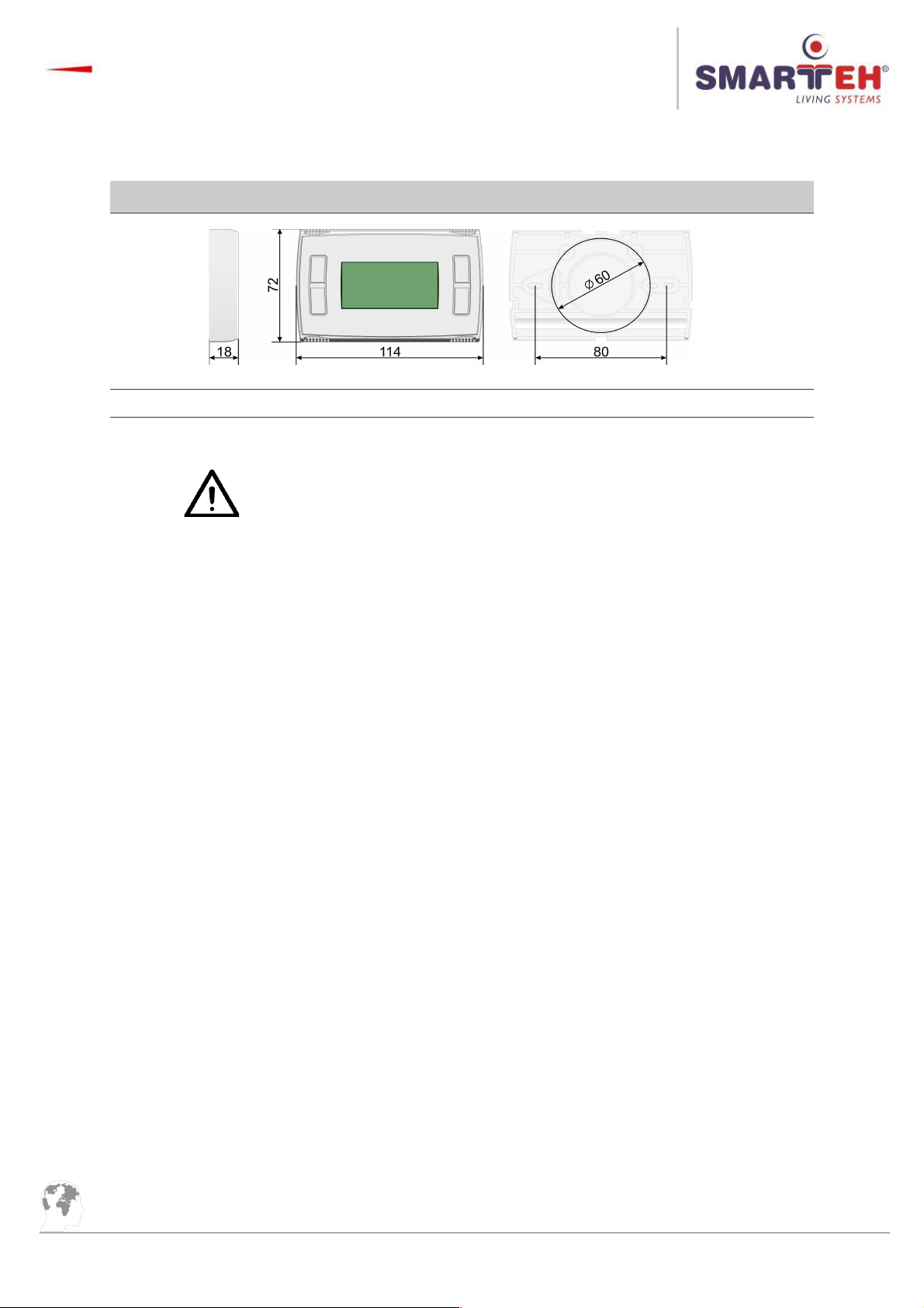
5.4 Mounting instructions
Figure 4: Housing dimensions
Dimensions in milimeters.
All connections, panel attachments and assembling must be done
while panel is not powered.
Panel should be positioned in the wall inside of the room. Avoid direct
sunlight or positioning near heating/cooling source object.
Panel is designed to be installed or placed vertically allowing air flow
from bottom to top.
1. Set the correct subnet (S1 switch) and wireless panel address (S2 switch) inside LPC-2.WP1H
(refer to the Table 4 and Table 5),
2. Mount the back plate in mounting frames (dose),
3. Insert 2x AA 1.5 V battery,
4. Attach front part of LPC-2.WP1H to the mounted back plate.
12

Longo programmable controller LPC-2.WP1H
5.5 Module labeling
Figure 8: Labels
Label 1 (sample): Label 2 (sample):
Label 1 descriptions:
1. LPC-2.WP1H is the full product name.
2. P/N: 225WP112001001 is the part number.
• 225 – general code for product family,
• WP1 – short product name,
• 12001 – sequence code,
• 12 – year of code opening,
• 001 – derivation code,
• 001 – version code (reserved for future HW and/or SW firmware upgrades).
3. D/C:01/10 is the date code.
• 01 – week and
• 10 – year of production.
Label 2 descriptions:
1. S/N: WP1-S9-1500000003 is the serial number.
• WP1 – short product name,
• S9 – user code (test procedure, e.g. Smarteh person xxx),
• 1000000003 – year and current stack code,
• 10 – year (last two cyphers),
• 00000190 – current stack number; previous module would have the stack number
00000189 and the next one 00000191.
13
S/N: WP1-S9-1000000003
LPC-2.WP1
P/N:225WP112001001
D/C: 01/10

Longo programmable controller LPC-2.WP1H
6 TECHNICAL SPECIFICATIONS
Table 6: Technical specifications
Power supply 2pcs. AA (LR6) battery
Battery lifetime Approximately 1.5 years
Operating frequency 868 Mhz
Wireless protocol WM-BUS
WM-Bus manufacturer ID SMT
Power consumption Less than 0.1 W
Dimensions (W x H x D) 75 × 49 × 29 mm
Weight 125 g
Maximum altitude 2000 m
Mounting position horizontal
Ambient temperature 0 to 50 °C
Ambient humidity max. 95 %, no condensation
Transport and storage temperature -20 to 60 °C
Protection class IP 20
14

Longo programmable controller LPC-2.WP1H
7 SPARE PARTS
For ordering spare parts following Part Numbers should be used:
LPC-2.WP1H T/RH control panel
LPC-2.WP1H P/N: 225WP112001001
Programming cable SMB
SMB P/N: 203SMB14001001
LPC-2.WA1 wireless adapter
LPC-2.WA1 P/N: 225WA112001001
Interconnection cable
ICM-x P/N: 203ICMxxxxxxxx
15

Longo programmable controller LPC-2.WP1H
8 CHANGES
The following table describes all the changes to the document.
Date V. Description
15.01.17 4 Technical data update.
30.08.16 3 General update.
01.12.14 2 The initial version, issued as LPC-2.WP1 User Manual.
16

Longo programmable controller LPC-2.WP1H
9 NOTES
17
 Loading...