


Smartec STC-3904/3902/3905
Day/Night High-Speed Dome Cameras
User Manual
www.smartec-security.eu

CONTENTS
Warning & Caution ------------------------------------------------------------------------------ 3
What's in the Box -------------------------------------------------------------------------------- 3
General Fratures --------------------------------------------------------------------------------- 4
Names of Each Part ----------------------------------------------------------------------------- 5
Installation ----------------------------------------------------------------------------------------- 6
A. Connection Method ------------------------------------------------------------------- 6
B. Ceiling Mount Type ------------------------------------------------------------------- 8
C. Embedded Mount Type ------------------------------------------------------------- 9
D. Pipe Mount Type --------------------------------------------------------------------- 10
E. Gooseneck Mount Type-------------------------------------------------------------- 12
F. Wall Mount Type----------------------------------------------------------------------- 13
G. Corner Mount Type ------------------------------------------------------------------- 14
H. Pole Mount Type ---------------------------------------------------------------------- 15
I. Indoor Housing Adaptor Type ------------------------------------------------------ 16
Ouick Operating Keys---------------------------------------------------------------------------- 18
Diagnostic------------------------------------------------------------------------------------------- 20
OSD Menu Setting--------------------------------------------------------------------------------- 21
A. OSD Menu Table --------------------------------------------------------------------- 21
B. DOME SET ----------------------------------------------------------------------------- 22
C. CAMERA SET ------------------------------------------------------------------------- 28
D. PRESET ------------------------------------------------------------------------------- 30
E. AUTO SCAN SET--------------------------------------------------------------------- 31
F. TOUR SET------------------------------------------------------------------------------ 32
G. PRIVACY SET ------------------------------------------------------------------------- 33
H. PATTERN SET------------------------------------------------------------------------- 34
I. ALARM SET --------------------------------------------------------------------------- 35
J. ALARM SET --------------------------------------------------------------------------- 36
DIP Switch Setting -------------------------------------------------------------------------------- 37
A. ID Setting ------------------------------------------------------------------------------- 37
B. 485 Termination------------------------------------------------------------------------ 39
C. Protocol --------------------------------------------------------------------------------- 39
D. Baud Rate Setting--------------------------------------------------------------------- 39
Trouble shooting ---------------------------------------------------------------------------------- 40
Specification---------------------------------------------------------------------------------------- 41
Dimensions ----------------------------------------------------------------------------------------- 42

CAUTION
RISK OF ELECTRIC SHOCK
DO NOT OPEN
CAUTI ON:
TO REDUCE THE RISK OF ELECTRIC SHOCK,
DO NOT REMOVE COVER (OR BACK).
NO USER SERVICEABLE PARTS INSIDE.
REFER SERVICING TO QUALIFIED SERVICE PERSONNEL.
WARNING & CAUTION
If you fail to read this information and handle
the product incorrectly, death or serious
injury may occur.
The unit should be installed by the trained
personnel
This symbol is intended to alert the user to the
presence of uninsulated "dangerous voltage"
within the produ ct's enclosure that may be of
sufficient magnitude to constitute a risk of electric
shock to persons.
This symbol is intended to alert the user to the
presence of important operating and maintenance
(servi
cing) instructions in the literature
accomp anying the appliance.
1. Camera
2. Ceiling Mount Bracket
3. Wrench
4. Screw (Ø3x6 screw---------2EA,
Ø4x16 screw-------5EA)
5. Safety W ire
6. Manual
7. Ceiling Cover
8. Cable ties
9. Terminal Block
(2 Pin--------------------------2EA,
3 Pin, 5 Pin, 6 Pin --------1EA)
What's in the Box ?
Switch off immediately if the product emits
smoke or abnormal heat.
Never install the product in area exposed oil or
gas.
Never install the product on a ceiling that cannot
hold its weight.
Never touch the power cord with wet hands.
Clean only with dry cloth.
Never install the product in extreme high or low
temperature.
Never drop, hit strongly nor vibrate the product.
Never expose the product to direct sunlight or
severe ray.
Never touch the front glass of the product.
Never install the product in areas exposed to
rain or water.

GENERAL FEATURES
World most silent speed dome camera
Equipped with silent and smooth timing belt and
special gear, low-noisy-technology enhances
durable quality of the camera by reducing the
mechanical vibration. This camera is the perfect
match, both indoor and outdoor, for demanding
security and monitoring burglars.
0.024º dome system accuracy with 1/8
micro step
With 0.024º technical accuracy, camera provides
excellent sensitive and delicate controlling on
preset mode by adapting 1/8 micro step and twin
gear system
Reliable RAM-Material
The mechanical stabilization improves the
durability and long life time of the camera by
using reliable materials especially, stepping
motor, slip ring, timing belt and power condenser.
This camera case is made of fire resisting
material that approved UL grade 94 V-0. It is
useful for indoor environment concerning about
the fire accident
Compensation function: preset position
The function provides absolute preset position
even in difficult applications where vibration and
strong winds may otherwise affect dome
performance.
Slip Ring for long life time (20milion
rotate ring tested)
Equipped with slip ring is passed by up to 20
millions rotate ring test within 6 months
Power misconnection protection on 485
terminals
This protection function prevents the
communication terminal from being out and
trouble when power source falsely connects to
the RS-485 terminals. Hi speed dome got a
patent for power misconnection protection on
RS-485 terminal
Filter changeable True Day/Night
Top quality images are assured under day and
night conditions due to the true day / night
camera with IR cut filter. Low light sensitivity is
further increased by the cameras digital slow
shutter.
Quick Operation Keys
This camera provides quick function keys to
allow control by most keyboards and DVRs that
have Pelco protocol support..
Various Surveillance Functions
Auto Scan repeats pan and tilt between two
preset positions with different speed and dwell
time.
8 Group Tour up to 8 Programmable Group
tours available and each group is consisting up to
60 presets step with different speed and dwell
time with 16 characters.
165 Preset positions up to 165 programmable
preset positions are available with 16 characters
8 Patterns up to 8 programmable user-defined
patters are available with 16 characters and each
one is consisting 50 seconds, total 400
8 Sectors up to 8 programmable user-defined
sectors are available with 16 characters
24 Privacy Masking Zones up to 24
programmable user-defined privacy masking
zones are available with 16 characters (18X, 26X
only)
4 Alarm input and 2 relay out up to 4 alarms
and 2 relay out available to match with preset,
tours, patterns.
300º/S 200O/S on Preset speed
The 360º full pan function moves through a
maximum of 350º /sec., enabling you to quickly
pinpoint the spot you want to watch. Tilt speed
provides through a maximum 250º /sec on
preset. On preset mode, the camera is set up to
300º /sec
200º /S Manual speed
This camera provides up to 200º /sec of manual
speed and it's adjustable from 100º /sec to 200º
/sec
1/4'' Sony Ex-View CCD
Equipped with Sony Ex-view HAD CCD
technology, these particular cameras provide
excellent sensitivity and low smear levels (18X
26X only)
Multiple languages and protocols
To convenience for the customers, this camera
provides several languages and protocols
including English, Italian, Polish and Pelco D,
Pelco P and Ultrak protocol
Intelligent Pan/Tilt Controlling
Pan and tilt speed compensation function linked
to zoom position

NAMES OF EACH PART
FIG. 1
1. Bubble
2. Lock Screw
3. DIP Switch 1
4. DIP Switch 2
5. Camera
6. Lock Holder
7. Power
8. Video Output
9. Loop RX
10. Loop TX
11. Power LED
12. Aux
13. Alarm
14. Mount Holder

INSTALLATION
A. CONNECTION METHOD
A-1. To separate camera body
Loosen Lock Screw 2mm to the counterclockwise using the wrench.
(Don't pull out the screw) (FIG. 2)
Separate the upper body from the lower body rotating counterclockwise. (FIG. 3, 4)
A-2. After separating, set DIP switches. (Refer to the page 37, 38 and 39)
A-3. To assemble camera body
Rotate the upper body clockwise to assemble both bodies (FIG. 5, 6)
Screw up using wrench clockwise. (FIG. 7)
● Don't screw tightly. It can be the cause of defect.
FIG. 2
FIG. 3
FIG. 4
FIG. 5
Screw up to flat with
the body surface.
LOCK
FIG. 6 FIG. 7
UNLOCK

INSTALLATION
A-4. Alarm : 4 Alarm input
A-5. AUX : DC 24V 1A can be used as an AUX terminal.
Turning on the light and remote control are possible using AUX.
A-6. TX : TX transmits Data signal received from RX to other equipment.
TX is convenient terminal for connection with Daisy Chain.
A-7. RX : RX are received Control Signal from controller or DVR.
A-8. Video out : BNC connector
A-9. P ower : AC 24V 1.0A adaptor
● Don't connect power source to Center terminal of Power.
A-10. Power on LED
IR SENSOR or DOOR SENSOR
AUX 2
AUX 1
SIGNAL
GND
(2,3,4 Same way of 1)
AUX 2
TERMINAL BLOCK
(FEMALE)
AUX 2
MONITOR
TERMINAL BLOCK
(MALE)
AC220/110V
AC24V ADAPTOR
CONTROLLER or DVR
OTHER CAMERA or DEVICE
FIG. 8

INSTALLATION
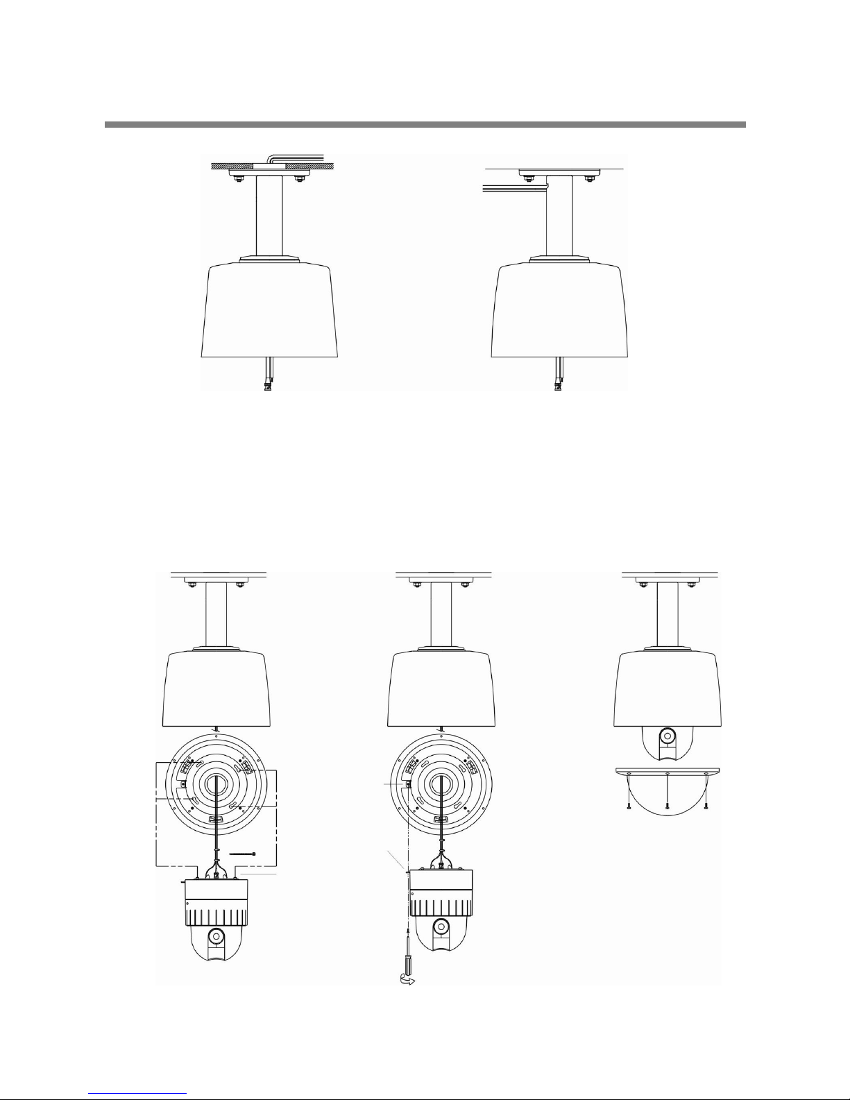
B. CEILING MOUNT TYPE
B-1. Find the places which are strong enough to support the camera, about 2kg.
B-2. Make a hole, Ø145mm, on the ceiling. (FIG. 9)
Hook the safety wire to suspension and the safety wire hold on the bracket. (FIG. 10)
B-3. Install the ceiling mount bracket by driving 4 screws, Ø4mm tapping screws. (FIG. 11)
B-4. You can make wires simple by cable ties. (FIG. 12)
B-5. Make the wires go though the square hole.
Insert mount holder and twist the camera counterclockwis e. (FIG. 13)
B-6. Fix the camera by driving a screw on lock holder1 and 2. (FIG. 14)
B-7. Install the cover by inserting cover lock and twisting clockwise. (FIG. 15)
1. CEILING MOUNT BRACKET 1ea
CONTENTS
SUSPENSION
SAFET Y WIR E
COVER HOLE
LOCK HOLDER 1.
SCREW (Ø4.0)
CEI LING BR ACKET
SAFET Y WIRE HOLE
MOUNTI NG HOLE
LOCK HOLDER 1.
CABLE TI E
LOCK HOLDER 2.
MOUNT HO LDE R
FIG. 10
FIG. 9 FIG. 11
FIG. 12
SCREW (M3.0)
COVER
COVER HOLE
COVER LOCK
FIG. 13 FIG. 14
FIG. 15

INSTALLATION
C. EMBEDDED MOUNT TYPE
C-1. Prepare a Ø190mm hole in the ceiling board.
Fix the safety wire to a suspension to prevent camera from falling.
Other side of safety wire is fixed to the safety wire hole. (FIG. 16)
C-2. Fold the Lock Levers then insert the Bracket into the Ceiling Hole.
Fix the Bracket to the ceiling using the driver. (FIG. 17)
C-3. Hereafter installation is same way of Ceiling Mount Type. (Refer to the page 8)
1. EMBEDDED MOUNT BRACKET 1ea
CONTENTS
SAFET Y WIRE HOLE
FIG. 16
LOCK LEVER
LOCK LEVER
LOCK LEVER
EMBEDED MOUNT
LOCK LEVER
FIG. 17
FIG. 18
SCREW (M3.0)

INSTALLATION
D. PIPE MOUNT TYPE
D-1. If you want to install the speed dome on the concrete wall, you need to make
12.5mm diameter 4 holes by drill like FIG. 19. (Depth 37mm)
D-2. Install SET ANCHOR BOLT on the holes.
D-3. Drive a cap on the pipe. (FIG. 20) .
D-4. After winding the THREAD SEAL TAPE, screw the bracket on the housing. (FIG. 21)
D-5. Fix SET ANCHOR BOLT of the bracket by nut.
1. PIPE MOUNT BRACKET 1ea 2. SET ANCHOR BOLT (W5/16) 4ea
3. CAP 1ea
CONTENTS
FIG. 19
4-Ø12.5mm Hole
Cap
THREAD SEAL TAPE
FIG. 20
FIG. 21
INSTALLATION
D-6. Tie the wire using the cable ties. (FIG. 23)
D-7. Place the Camera Mount Holder on the Bracket Mount Hole.
To insert them easily, keep 10° interval of Lock Holder1 and Lock Holder2. (FIG. 24)
D-8. Screw up the bubble tightly to prevent water leakage. (FIG. 25)
FIG. 22
<The cable into ceiling> <The cable out of ceiling>
LOCK HOLDER 1.
FIG. 23 FIG. 24
FIG. 25
LOCK HOLDER 2.
MOUNT HO LDE R
CABLE TI E

INSTALLATION
E. GOOSENECK MOUNT TYPE
E-1. If you want to install the speed dome on the concrete wall, you need to make
12.5mm diameter 4 holes by drill like FIG. 26. (Depth 37mm)
E-2. Install SET ANCHOR BOLT on the holes.
E-3. Drive a cap on the pipe. (FIG. 27)
E-4. After winding the THREAD SEAL TAPE, screw the bracket on the housing. (FIG. 28)
E-5. Fix SET ANCHOR BOLT of the bracket by nut.
E-6. Camera installation is the same as that of Pipe mount bracket installation.
(Refer to page 11)
1. GOOSENECK MOUNT BRACKET 1ea 2. SET ANCHOR BOLT (W5/16) 4ea
3. CAP 1ea
CONTENTS
FIG. 26
4-Ø12.5mm Hole
Cap
THREAD SEAL TAPE
FIG. 27
FIG. 28
FIG. 29
<The cable into ceiling> <The cable out of ceiling>

INSTALLATION
F. WALL MOUNT TYPE
F-1. If you want to install the speed dome on the concrete wall, you need to make
12.5mm diameter 4 holes by drill like FIG. 30. (Depth 37mm)
F-2. Install SET ANCHOR BOLT on the holes.
F-3. Fix SET ANCHOR BOLT of the bracket by nut.
To install Wall Mount Bracket.
Tip> Select a ceiling board strong enough to hold 4 times the total weight if camera.
(Weight combined camera: approx. 5kg)
F-4. Screw up the Bracket tightly using the wrench(M4.0) after putting the rising into
the hole. (FIG. 31)
F-5. Camera installation is the same as that of Pipe mount bracket installation.
(Refer to page 11)
1. WALL MOUNT BRACKET 1ea 2. SET ANCHOR BOLT (W5/16) 4ea
CONTENTS
FIG. 30
4-Ø12.5mm Hole
<The cable out of ceiling>
FIG. 31

INSTALLATION
G. CORNER MOUNT TYPE
G-1. First mark the position of holes placing the corner mount bracket.(FIG. 33)
Make Ø12.5mm 4 holes by drill. (Depth 37mm)
G-2. Install SET ANCHOR BOLT on the holes.
G-3. Fix the wanted bracket (wall mount bracket, gooseneck mount bracket) on the corner
mount bracket with 4ea of M10 bolt before you Install the corner mount bracket.(FIG. 34)
G-4. Screw the set anchor bolt of the bracket by nut on the wall. (FIG. 35)
G-5. Housing and camera installation is the same as that of Pipe mount bracket installation.
(Refer to page 10, 11)
<The cable into ceiling>
1. CORNER MOUNT BRACKET 1ea 2. SET ANCHOR BOLT (W5/16) 4ea
3. M10 BOLT & NUT 4ea
CONTENTS
FIG. 33
Mark t he positions of holes
M10.0 BOLT
GOOSENECK MOUNT BRACKET
CORNER MOUNT BRACKET
CORNER MOUNT BRACKET
FIG. 35
FIG. 34

INSTALLATION
H. POLE MOUNT TYPE
H-1. Fix the wanted bracket on the corner mount bracket with 4ea of M10 bolt before you Install
the corner mount bracket. (FIG. 36)
H-2. Tie the bracket with sus band tightly. (FIG. 37)
H-3. Housing and camera installation is the same as that of Pipe mount bracket installation.
(Refer to page 10, 11)
1. POLE MOUNT BRACKET 1ea 2. SUS BAND 2ea
3. M10 BOLT & NUT 4ea
CONTENTS
WALL MO UNT BRA CKET
FIG. 36
FIG. 37
POLE MOUNT BRACKET
M10 BOLT
SUS BAND

INSTALLATION
I. INDOOR HOUSING ADAPTOR TYPE
I-1. After screwing pipe nut on the pipe and inserting it into housing, fix the pipe with housing
By screwing the nut again. (FIG. 38)
I-2. Fix the ceiling bracket on the housing by M4.0 screw. (FIG. 39)
I-3. Tie the wire using the cable tie. (FIG. 39)
I-4. Let the wires to be put into the square hole. (FIG. 39)
Place the Camera Mount Holder on the Bracket Mount Hole.
To insert them easily, keep 10° interval of Lock Holder1 and Holder 2.
1. INDOOR HOUSING 1ea 2. PIPE NUT 2ea
CONTENTS
PIPE NUT
FIG. 38
LOCK HOLDER 1.
CABLE TI E
FIG. 39
MOUNT HO LDE R
LOCK HOLDER 2.
SCREW (Ø4.0)
CEI LING BR ACKET
MOUNTI NG HOLE
SAFET Y WIRE HOLE
LOCK HOLDER 1.
COVER HOLE

INSTALLATION
I-5. To assemble, rotate the camera clockwise by 10°. (FIG. 40)
I-6. Screw up Lock Holders with screws. (FIG. 41)
I-7. Assemble the cover.
Fix three Cover Locks to three Cover Holes rotating clockwise. (FIG. 42)
FIG. 40
SCREW (M3.0)
LOCK HOLDER 1.
LOCK HOLDER 2.
FIG. 41
COVER HOLE
COVER LOCK
FIG. 42

QUICK OPERATING KEYS
The dome supports Pelco-D/P, SAMSUNG and VICON protocols.
The dome may be used with any controller or DVR etc that supports the Pelco D and Pelco
P protoc ols.
The default setting of the dome is Pelco D / P (auto detection) with 2400 bps (baud rate).
[PELCO D/P PROTOCOLS]
The comprehensive feature set of the dome is available from Pelco compatible controllers
via quick operation keys as defined below.
1-64 + preset and 100~200 + preset are used for normal user presets.
Presets 65-99 + are reserved for special functions.
For example, to enter OSD MENU, press the button 95 + PRESET
<Quick Operation Key Table 1>
Number Note Function
1~64,100~200 +Preset Preset Executing Preset 1 ~ 64, 100~200
65 +Preset Preset Status Display Preset Status
66 +Preset Auto Scan Executing Auto Scan
67 +Preset Auto Flip Selectable On/Off in Auto Flip mode
68 + Preset Camera Reset Re-setting Zoom camera module
70 + Preset VIB CORR Selectable On/Off in Picture Stabilization function
71~78 + Preset Group Tour Executing Group Tour #1 ~ #8
81~88 + Preset Pattern Executing Pattern #1 ~ #8
91 + Preset Zero Position Searching Pan / Tilt Zero Position
92 + Preset Freeze Select Freeze image when camera is working
93 + Preset BLC Selectable On/Off in BLC function
94 + Preset Day / Night Selectable Day / Night / Auto Mode
95 + Preset OSD Entering OSD Main Menu
96 + Preset Focus Adjust Focus adjust
97 +Preset Alarm Selectable Enable/Disable all Alarms
98 +Preset AUX 1 Selectable On/Off in Aux1
99 +Preset AUX 2 Selectable On/Off in Aux2
<Quick Operation Keys Table 2: Use these function keys if controller has these keys>
Menu Function
Tilt Up / Down Sub menu cursor moves up / down
Pan Left / Right Enter to the sub menu or status change or decrement
Focus Near Using for Enter key when user select YES or NO
Focus Far Using for function changing keys when set coordinate
Zoom Tele Status cursor to the right
Zoom Wide Status cursor to the left
● 65 + preset : "Preset Status" is displayed, to remove this screen, press Focus Near button.
● 70 + preset : This feature provides picture stabilization image and it is by EX980S (P)
module only.
This feature is operating by preset number but not included in OSD main menu.
This is optional function due to zoom module

QUICK OPERATING KEYS
● 92 + preset : This feature freezes the current live image during tour, auto scan or pattern
operation. When you press 92 + preset button, the image freezes but the camera is still
working as per operation such as tour, pattern or auto scan. To return to normal images,
press 92 + preset button again.
This feature is operated by preset number but not included in OSD main menu.
● Due to Zoom camera module, OSD Menu not provides every feature.
In this case, "Not available" is displayed on the monitor.
[MAXPRO PROTOCOL]
If user wants to choose Maxpro Protocol, the user may change the dip switch first.
(Refer to Page #32 DIP SWITCH SETTING - PROTOCOL)
Baud Rate: 9600 (Maxpro default)
Maxpro protocol is almost same as Pelco D/P protocol operating system but some special
features are different way as noted below
<Quick Operation Key Table 1>
Number Note Function
1~64,100~200 +Preset Preset Executing Preset 1 ~ 64, 100~200
67 +Preset Auto Flip Selectable On/Off in Auto Flip mode
80~85 + Preset Pattern Executing Pattern #1 ~ #6
86 + Preset Auto Scan Executing Auto Scan
87~89 + Preset Group Tour Executing Group Tour #1 ~ #3
90 + Preset OSD Entering OSD Main Menu
91 + Preset Zero Position Searching Pan / Tilt Zero Position
92 + Preset Freeze Select Freeze image when camera is working
93 + Preset BLC Selectable On/Off in BLC function
94 + Preset Day / Night Selectable Day / Night / Auto Mode
95 + Preset OSD Entering OSD Main Menu
96 + Preset Focus Adjust Focus adjust
97 +Preset Vir. Corr. Selectable On/Off in Vibration Correction function
98 +Preset AUX 1 Selectable On/Off in Aux1
99 +Preset AUX 2 Selectable On/Off in Aux2
<Quick Operation Keys Table 2: Use these function keys if controller has these keys>
Menu Function
Tilt Up / Down Sub menu cursor moves up / down
Pan Left / Right Enter to the sub menu or status change or decrement
Focus Near Using for Enter key when user select YES or NO
Focus Far Using for function changing keys when set coordinate
Zoom Tele Status cursor to the right
Zoom Wide Status cursor to the left
● Due to Zoom camera module, OSD Menu provides not every feature. In this case,
“Not available” is displayed on the monitor.

DIAGNOSTIC
Whenever the dome is powered on, a standard diagnostic is operated.
A. Pan Origin Test
Zero point of Pan is located during the Panning test.
B. Tilt Origin Test
Zero point of Tilt is located during the Tilt test.
C. TX connection Test
Wait for 60 seconds for TX Connection Test,
During 60 seconds, the camera is must received a signal by any control equipment
as DVR or controller.
Then Ok is displayed then automatically verifying TX Connection Test.
* If "Not Tested" is displayed in the test,
- The result which is not received any signal from DVR or controller
- Wrong connecting way such as the protocol, baud rate or RS-485 connection.
The use may check the install way carefully.
D. Camera Comm. Test
Camera communication is also checked.
OK should be displayed in these four tests before installation.
If all the above Tests are OK, “NOW EEPROM CHECKING” and “ALL DATA INITIALIZING” is
displayed and the camera is read y to operate.
CAMERA ID : 001
BAUD RATE : 2400 BPS
WAITING………
PAN ORIGIN TEST OK
TILT ORIGIN TEST OK
TX CONNECTION TEST OK
CAMERA COMM TEST OK

OSD MENU SETTING
A. OSD MENU TABLE
AUTO SCAN SET
START ANGLE : XXX.X.XX.X
END ANGLE : XXX.X.XX.X
DIRECTION : CW
ENDLE SS : OFF/ ON
SPEED : 10º/s
DWELL TIME : 03
SAVE AN D EXIT
EXIT
PRESET SET
PRESET NO: 001
PRESET ID: PRESET01□□□□□□□□□
PAN:XXX.X TILT:XX.X
SAVE
EXIT
CAMERA SET
FLICKER : OFF/ON
MIRROR : OFF/ON
APERTURE : 10
D ZOOM : OFF/ON
WB MODE : AWB MODE
PIC FLIP : OFF/ON
BLC : OFF/ON
D/N MODE : AUTO
DSS MODE : OFF/ON
EXIT
DOME SET
CAMERA ID : CAM1□□□□□□□□□□□□
RECOVER : OFF
MANUAL SPEED : 150°/S
AUTO FLIP : OFF
ZOOM SPEED : FAST
ALARM : DISABLE
LANGUAGE : ENG LISH
[NEXT PAGE]
SAVE AN D EXIT
EXIT
MAIN ME NU
DOME SETUP
CAMERA SET
AUTO SC AN
TOUR
PRAVA CY
PATTE RN
ALARM
SECTOR
EXIT
SECTOR SET
SECTO R NO : 01
SECTO R ID : SECTOR01□□□
SECTOR START : XXX.X.XX.X
SECTOR END : XXX.X.XX.X
SAVE
EXIT
ALARM SET
ALARM NO. : 01
ALARM INPUT : OFF/NO/NC
ALARM ACT : 001
SAVE
EXIT
PATTE RN SET
PATT NO. : 01
PATT TITLE PATTERN 01□□□
DATA FILL : 100%
SAVE
EXIT
PRIVA CY SET
PRIVACY NO. : 01
DISPL AY : ON/OFF
ACTION : MOV E/ADJU ST
SAVE
EXIT
TOUR SET
TOUR NO. : 01
TOUR TITLE : TOUR01□□□□ □□
TOUR STEP : 01
PRESE T NO : 01
DWELL TIME : 3
S PE E D : 3 00 º /S
SAVE AN D EXIT
EXIT
[INITIALIZATION]
[TOUR CLEAR]
[PRESET CLEAR]
[SECTOR CLEAR]
[PRIV ACY CLEA R]
[PATT ERN CLEA R]
[LOAD OPTIMIZED DEFAULT]
[REVIOUS PAGE]
[SYST EM STA TUS]
PROTOCOL : PEL CO D,P
BAUD RA TE : 240 0BPS
FIRMWARE VER. : 2.00
UPGRA DED DATE : 02.28, 06
CAMER A MODULE : EX980P
[PREVIOS PAGE]
OSD D ISPLAY
CAMERA ID : OFF/ON
PRESET ID : OFF/ON
SECTOR ID : OFF ON
COORD INATE : ON/OFF
[PREV IOUS P AGE]
NEXT PA GE
SYSTE M LO CK : O FF
[PASS WORD]
[OSD DISPLY]
[SYST EM STA TUS]
[INITIALIZATION]
[PREV IOUS P AGE]

OSD MENU SETTING
To enter OSD Menu, press the button 95+Preset (Maxpro 90+Preset) then OSD Main Menu
is displayed.
● Use the joystick up down to move the position and left right to make selection.
B. DOME SET
To enter Dome setup, use the joystick right to move when cursor on dome setup.
B-1. DOME SET - CAMERA ID
To set camera name, and select a title of up to 16 characters using left or right direction
keys or joystick. Press ZOOM TELE button to move to the next character from left to
right direction and ZOOM WIDE button to move to the next character from right to left
direction. (Space displays when £ Appears)
MAIN MENU
DOME SETUP
CAMERA SET
PRESET
AUTO SCAN
TOUR
PRAVACY
PATTERN
ALARM
SECTOR
EXIT
DOME SET
CAMERA ID : CAM1□□□□□□□□□□□□
RECOVER : OFF
MANUAL SPEED : 150°/S
AUTO FLIP : OFF
ZOOM SPEED : FAST
ALARM : DISABLE
LANGUAGE : ENGLISH
[NEXT PAGE]
SAVE AND EXIT
EXIT
DEFAULT SETTING

OSD MENU SETTING
B-2. DOME SET - RECOVER
This feature allows the dome to revert to a specific programmed action when the dome
has not received a command for the recovery timer period.
Actions can be Auto scan, group tour, preset, and pattern. The recover time can be
programmed from 15 second to 90 seconds. The default setting is OFF.
B-3. DOME SET - MANUAL SPEED
Manual Speed of Pan/Tilt is selectable from 100º/sec up to 200 º /sec.
The default setting is 150º/sec.
B-4. DOME SET - AUTO FLIP
Auto Flip is available and the default setting is OFF. Move joystick right or left direction
is for selecting OFF or ON. The default setting is OFF.
This feature is working as 67 + preset button.
B-5. DOME SET - ZOOM SPEED
Zoom speeds are selectable FAST or SLOW mode. Move joystick to the right direction
for selecting FAST or SLOW. The default setting is FAST.
B-6. DOME SET - ALARM
You must enable the alarms for them to operate. The default setting is DISABLED.
This function can be recalled by pushing 97 + preset button.
B-7. DOME SET - LANGUAGE
Multiple languages are selectable here including English, Italian and Polish.
Move joystick to the right or left direction to select language.
The default setting is ENGLISH.
B-8. DOME SET - [NEXT PAGE]
B-8-1. DOME SET - [NEXT PAGE] - SYSTEM LOCK
All stored dome settings can be password protected to prevent unauthorized changes.
In order to enter [PASS WORD] page, the system lock status must firstly be set as ON.
The default setting is OFF.
DOME SET
SYSTEM LOCK : OFF
[PASS WORD]
[OSD DISPLAY]
[SYSTEM STATUS]
[INITIALIZATION]
[PREVIOUS PAGE]
DEFAULT SETTING

OSD MENU SETTING
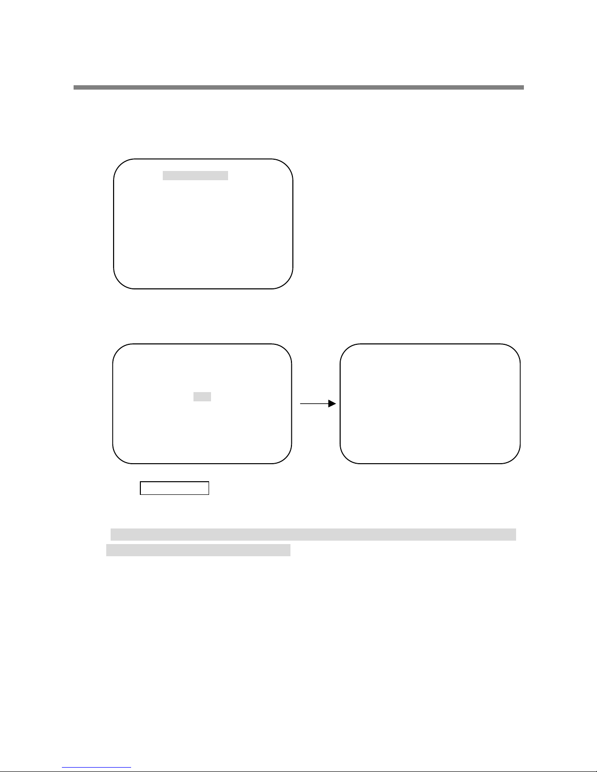
B-8-2. DOME SET - [NEXT PAGE] – [PASSWORD]
To enter this page to set a password, move joystick or pan key in the right direction.
The password must be set by preset number from 001 to 255 (Default 99)
Enter any number from 001~255 on the password blank area and again on the confirm
blank area. Then “CONFIRMED” is displayed on the monitor and the menu will go back
to the previous page automatically.
<CONFIRMED> <CANCELLED>
If you press an incorrect number between PASSWORD and CONFIRM, “CANCELLED” is
displayed on the monitor when you press FOCUS FAR key, “CANCELLED” will be
displayed on the monitor, it goes to previous page.
* When a password has been set, the operator must enter the correct password in
order to enter OSD MAIN MENU, or to change any of the domes configuration data.
* If you set a password you must ensure that it does not get lost. If this happens the
dome must be returned for workshop repair.
ENTER PASSWORD
BY ENTERING PRESET CODE
PASSWORD ***
CONFIRM ***
DEFAULT SETTING
ENTER PASSWORD
BY ENTERING PRESET CODE
PASSWORD ***
CONFIRM *** CONFIRMED
ENTER PASSWORD
BY ENTERING PRESET CODE
PASSWORD ***
CONFIRM *** NOT CORRECT

OSD MENU SETTING
B-8-3. DOME SET - [NEXT PAGE] - [OSD DISPLAY]
The camera ID setting defines whether the camera OSD display is displayed or
switched off.
B-8-4. DOME SET - [NEXT PAGE] - [SYSTEM STATUS]
This page shows the information of this camera.
- Protocol and baud rate are shown due to the dip switch setting
(Refer to page 30, 31 and 32)
- Firmware version and upgraded date will change if upgraded.
- Camera module is settling as follows
* 18X : SONY ZOOM MODULE # EX480C
* 26X : SONY ZOOM MODULE # EX980C / EX980CS
* 23X : SAMSUNG ZOOM MODULE # SDM231
* 30X : SAMSUNG ZOOM MODULE # SDM300
* 36X : SONY ZOOM MODULE # Ex1000 OR EX1010
OSD DISPLAY
CAMERA ID : OFF
PRESET ID : OFF
SECTOR ID : OFF
COORDINATE : ON
[PREVIOUS PAGE]
DEFAULT SETTING
SYSTEM STATUS
PROTOCOL : PELCO, P
BAUD RATE : 2400 BPS
FIRMWARE VER. : 2.01
UPGRADED DATE : 02.28,06
CAMERA MODULE : EX980SP
[PREVIOUS PAGE]
DEFAULT SETTING
OSD MENU SETTING
B-8-5. DOME SET - [NEXT PAGE] - [INITIALIZATION]
To clear the current settings select the item that you wish to reset back to factory defaults.
- To clear the memorized data, move the joystick or pan right key until the cursor is on
the required item.
Press FOCUS NEAR button when the cursor is at YES in order to clear memorized
data. Then each item such as tour, preset, and sector will flicker f or about 2~3
seconds. After this process, the menu is returned to the previous page.
* Use the above method for [PRESET CLEAR], [SECTOR CLEAR],[PRIVACY CLEAR],
[PATTERN CLEAR], [TOUR CLEAR].
INITIALIZATION
[TOUR CLEAR]
[PRESET CLEAR]
[SECTOR CLEAR]
[PRIVACY CLEAR]
[PATTERN CLEAR]
[LOAD OPTIMIZED DEFAULT]
[PREVIOUS PAGE]
TOUR CLEAR
ARE YOU SURE? YES NO
TOUR CLEAR

OSD MENU SETTING
- To clear all data and return to factory defaults, move the joystick right or press the pan
right key to when the cursor is at [LOAD OPTIMIZED DEFAULT] to enter the
next page.
- Move joystick or the pan right key so that the cursor is over YES, then press
the FOCUS NEAR button.
“ALL DATA INITIALIZING” is then displayed for about 5~7 seconds and then the menu
is returned to the previous page automatically.
B-9. DOME SET - [NEXT PAGE] - SAVE AND EXIT
To saving the memorized data and escape this page, move joystick to the right direction
when cursor is at SAVE AND EXIT.
B-10. DOME SET - [NEXT PAGE] - EXIT
In order not to save any data and wants to escape this page, move joystick to the right
direction when cursor is at EXIT.
LOAD OPTIMIZED DEFAULT
ARE YOU SURE? YES NO
NOW EEPROM
CHECKING
ALL DATA
INITIALIZING

OSD MENU SETTING
C. CAMERA SET
C-1. CAMERA SET - FLICKERLESS
The flickerless f eature has options of 50Hz and 60Hz. The default setting is OFF
(NTSC: 60Hz / PAL: 50Hz). The flickerless mode only needs to be set when there is a
mismatch between the power frequency and camera sync rate.
The default setting is OFF.
C-2. CAMERA SET - MIRROR
This feature literally swaps the image left and right as if looking into a mirror.
The default setting is OFF.
C-3. CAMERA SET - APERTURE
Aperture correction enhances the picture details and sharpness by increasing the gain
of the camera. Increase the value to sharpen the image, decrease to soften it The
default setting is 10. (the aperture level is from 01 ~ 15)
C-4. CAMERA SET - D ZOOM
If neabled digital zoom is applied when the zoom lens has reached its maximum
Optical zoom in capability The default setting is OFF.
C-5. CAMERA SET - WB MODE
White balance functions has 4 modes and may need to be changed depending
On the situation.
* AWB Mode 3,200ºK to 6, 000ºK (Default)
* Indoor up to 3,200ºK
* Outdoor up to 5,80ºoK
* ATW Mode - 2,000ºK to 10, 000ºK
CAMERA SET
FLICKER : OFF
MIRROR : OFF
APERTURE : 10
D ZOOM : OFF
WB MODE : AWB MODE
PIC FLIP : OFF
BLC : OFF
D/N MODE : AUTO
DSS MODE : OFF
EXIT
DEFAULT SETTING

OSD MENU SETTING
C-6. CAMERA SET - PIC FLIP
The picture flip feature swps the top and bottom of the image, literally inverting it.
The default setting is OFF.
C-7. CAMERA SET - BLC (Back Light Compensation)
The default setting is OFF and BLC modes can be OFF/ON.
* OFF Backlight compensation is not activated.
* ON Back light compensation is activated.
This function can be recalled by pushing 93 + preset button.
C-8. CAMERA SET - D/N MODE
The dome camera can operate in day /night mode and will switch depending on
lighting conditions. Alternatively it can be forced into color only mode.
The default setting is AUTO MODE. This function can be recalled by pushing
94 + preset button.
C-9. CAMERA SET - DSS MODE (DIGITAL SLOW SHUTTER)
If digital slow shutter is enabled the exposure time of the camera is increased, this
allowing more light to be collected and improving low light response. This setting
should not be enabled if the dome is touring at night or fast moving objects are likely
to be in the scene as smearing is also increased.
The default setting is OFF.
C-10. CAMERA SET - EXIT
To escape this page, move the joystick right or press the pan right key.

OSD MENU SETTING
D. PRESET SET
D-1. PRESET - PRESET NO.
Up to 165 preset positions are available.
Use the joystick or pan left/right keys to select the number.
D-2. PRESET - PRESET ID
To create preset titles use the joystick or pan left/right keys to navigate the menu.
The ZOOM TELE button moves to the next character from left to right and
ZOOM WIDE button moves to the next character from right to left
(Space displays when £ Appears)
D-3. PRESET - PAN: XXX.X TILT: XX.X
Press FOCUS FAR button in order to set preset position then, use the joystick or pan
left/right keys to the position where memorized preset number .is needed.
Then press FOCUS FAR button again after setting a preset location.
D-4. PRESET - SAVE
Move the joystick right or press the pan right key when the cursor is at SAVE and
then the cursor will be located on Preset ID for the continuous preset No. setting.
D-5. PRESET - EXIT
To escape this page, move joystick to the right direction.
PRESET SET
PRESET NO :001
PRESET ID :PRESET001□□□□□□□□□
PAN: XXX.X TILT: XX.X
SAVE
EXIT
DEFAULT SETTING

OSD MENU SETTING
E. AUTO SCAN SET
● 66 + preset (Maxpro: 86+Preset) button is working as AUTO SCAN after setting.
E-1. AUTO SCAN - START ANGLE
To set the start position, press FOCUS FAR button then move the dome to the
required start position. Press FOCUS FAR button again is to escape.
E-2. AUTO SCAN - END ANGLE
To set the end position, press FOCUS FAR button then move the dome to the
required end position. Press FOCUS FAR button again is to escape.
E-3. AUTO SCAN - DIRECTION
Auto Scan directions are available as CW or CCW.
* CW: Clock wise direction (Default)
* CCW: Count Clock Wise Direction.
E-4. AUTO SCAN - ENDLESS
Auto Scan can be set to endless rotation by enabling the endless option.
The default setting is OFF.
E-5. AUTO SCAN - SPEED
The scan speed can be programmed from 05º/S up to 35 º/S.
The default setting is 10º/S.
E-6. AUTO SCAN - DWELL TIME
The dwell time at the start and end points can be programmed from 1 second to
30 seconds. The default setting is 03 seconds.
E-7. AUTO SCAN - SAVE AND EXIT
To save the memorized data and escape this page, move the joystick right or press
the pan right key when the cursor is at SAVE AND EXIT.
E-8. AUTO SCAN - EXIT
To escape this page, move joystick to the right direction.
AUTO SCAN SET
START ANGLE : XXX.X.XX.X
END ANGLE : XXX.X.XX.X
DIRECTION : CW
ENDLES : OFF
SPEED : 10º/S
DWELL TIME : 03
SAVE AND EXIT
EXIT
DEFAULT SETTING

OSD MENU SETTING
F. TOUR SET
8 Programmable tours can be set and each tour can have up to 64 preset steps.
After setting up the tours the 71~78 + preset buttons launch group tours # 1~8.
● Maxpro protocol provides three (3) quick operation keys (87~89 + preset) for Group
tour but it is possible to set up to Group tour #8.
F-1. TOUR SET - TOUR NO.
Up to 8 group tours can be programmed.
F-2. TOUR SET - TOUR TITLE
To set a tour title, use the joystick left/right or pan left/right keys. Each title can have up
to 16 characters. Press ZOOM TELE button to move the next character from left to the
right and ZOOM W IDE button to move the next character from right to left (Space
displays when £ appears) The tour title is not displayed on the monitor and is only for
the reference of user.
F-3. TOUR SET - TOUR STEP
Each tour group consists of up to 60 preset steps with diff erent dwell time and speed.
It is possible to match any preset # for any tour step.
F-4. TOUR SET - PRESET NO.
For each tour step it is possible to select any preset number up to 64.
The default setting is BLK
F-5. TOUR SET - DWELL TIME
Dwell time can be programmed from 1-99 seconds. The default setting is 03 seconds.
F-6. TOUR SET - SPEED
Each tour step can be set with a different speed up to 200º/S and it is selectable from
10°/S. The default setting is 200º/S.
F-7. TOUR SET - SAVE
To save the memorized data and escape this page, move the joystick right or press the
pan right key when cursor is at SAVE
F-8. TOUR SET - EXIT
To escape this page, move joystick to the right direction
TOUR SET
TOUR NO : 01
TOUR TITLE : TOUR01□□□□□□□□□□
TOUR STEP : 01
PRESET NO. : 01
DWELL TIME : 03
SPEED : 300º/S
SAVE AND EXIT
EXIT
DEFAULT SETTING

OSD MENU SETTING
G. PRIVACY SET
24 Privacy masking zones can be set.
G-1. PRIVACY SET - PRIVACY NO.
Up to 4 privacy masking zones can be set.
G-2. PRIVACY SET - DISPLAY
Move the joystick right or left or press pan right/left to set ON in order to show the
selectable block in the center of the monitor. This block appears as a translucent
square with blue colour when set ON. The default setting is OFF.
G-3. PRIVACY SET - ACTION (MOVE / ADJUST)
To set the blocking area, press FOCUS FAR button when MOVE MODE is displayed.
Then use the joystick or pan keys to the user defined area in order to set the blocking
area. Then press FOCUS FAR button again to escape from MOVE MODE.
To adjust the size of the blocking area, move the joystick or use the pan keys when
the cursor is on ACTION. After it has changed to ADJUST MODE, press FOCUS FAR
button in order to adjust the size of the blocking area. The size of the blocking area can
be adjusted by using joystick up/down or left right ? or the pan and tilt keys.
After adjusting the size of the blocking area, press FOCUS FAR button to escape the
ADJUST mode.
* ADJUST: You can change the masking size by using the joystick or pan keys
* MOVE: You can move the masking area by using the joystick or pan keys (Default)
G-4. PRIVACY SET - SAVE
After setting the privacy masking zone, to save the data, move the joystick right or pan
right key when the cursor is on SAVE. After saving the data, the cursor moves to
PRIVACY NO.2 automatically to prepare f or the next privacy masking zone.
G-5. PRIVACY SET - EXIT
To esc ape this page, move the joystick right.
PRIVACY SET
PRIVACY NO : 01
DISPLAY : OFF
ACTION : MOVE
SAVE
EXIT
DEFAULT SETTING

OSD MENU SETTING
H. PATTERN SET
8 programmable patterns are available with 16 characters of title.
After set the data to the each pattern # 1~8, 81~88+ preset buttons are working as
Pattern # 1~8.
● Maxpro protocol provides six (6) quick operation keys (80~85 + preset) for patterns
but it is possible to set up to pattern #8.
H-1. PATTERN SET - PATT NO.
Up to 8 programmable user-defined patterns are available.
H-2. PATTERN SET - PATT TITLE
To set PATTERN TITLE move Joystick left/right or use the pan keys.
Press ZOOM TELE button moves to the next character from the left / right and
ZOOM WIDE button moves to the next character from the right / left (Space displays
when£ appears) The pattern title is not displayed on the monitor, but only for the
reference of the user.
H-3. PATTERN SET - DATA FILL
To memorize a pattern, press FOCUS FAR button in order to start the process.
The progress is shown as % filled. Press FOCUS FAR button again in order to escape.
H-4. PATTERN SET - SAVE
To save the memorized pattern data, move the joystick right or press the pan right key
when the cursor is on SAVE. Then the cursor moves to the PATT NO.02 in order to
prepare for the next pattern.
H-5. PATTERN SET - EXIT
To escape this page, move the joystick right or press the pan right key.
PATTERN SET
PATT NO : 01
PATT TITLE : PATTERN01□□□□□□□
DATA FILL : 100%
SAVE
EXIT
DEFAULT SETTING

OSD MENU SETTING
I. ALARM SET
4 Alarm inputs are available and each alarm is activating to presets, group tours or
patterns.
I-1. ALARM SET - ALARM NO.
Up to 4 alarms are selectable by using joystick right or pressing the pan right key when
the cursor is on ALARM NO.
I-2. ALARM SET - ALARM INPUT
Alarm inputs can be programmed as NC (Normally Close) or NO (Normally Open)
The default setting is OFF
I-3. ALARM SET - ALARM ACT
Active alarms can trigger modes such as presets, Group tours 1-8, and Patterns 1-8.
Use the joystick or pan keys to select any preset number, group tour no. or pattern no.
I-4. ALARM SET - SAVE
After setting up the alarm features, to save the data move the joystick right or press
the pan right key when the cursor is on SAVE. After saving the data, the cursor moves
to Alarm NO.2 automatically to prepare for the next alarm.
I-5. ALARM SET - EXIT
To escape this page, move the joystick right or press the pan right key.
* Before activating Alarms, you must set ALARM ENABLE at DOME SET ALARM
ENABLE(Refer to page 23)
ALARM SET
ALARM NO : 01
ALARM INPUT : OFF
ALARM ACT : 001
SAVE
EXIT
DEFAULT SETTING

OSD MENU SETTING
J. SECTOR SET
Up to 8 programmable sectors are available with 16 characters.
This feature is useful to memory the certain location such as parking zone or so on.
J-1. SECTOR SET - SECTOR NO.
Up to 8 programmable sectors are available.
J-2. SECTOR SET - SECTOR ID
To set a SECTOR ID, use the joystick or pan left/right keys.
Press ZOOM TELE button to move to the next character from left to right and
ZOOM W IDE button to move to the next character from right to left
(Space displays when £ appears)
J-3. SECTOR SET - SECTOR START
To set a SECTOR START position, press FOCUS FAR button then move the joystick
Or pan keys to set the position. Press FOCUS FAR button again to escape.
J-4. SECTOR SET - SECTOR END
To set a SECTOR END position, press FOCUS FAR button then move the joystick or
Pan keys to set the position. To press FOCUS FAR button again to escape.
J-5. SECTOR SET - SAVE
After setting the SECTOR positions, to save the data move the joystick right or press
the pan right key when the cursor is on SAVE. After saving the data, the cursor moves
to SECTOR NO.2 automatically to prepare for the next SECTOR.
J-6. SECTOR SET - EXIT
To escape this page, move the joystick right or press the pan right key.
K. EXIT
To escape OSD Main Menu, move joystick to the right or left direction then this camera
is ready to operate.
SECTOR SET
SECTOR NO : 01
SECTOR ID : SECTOR01□□□□□□□□
SECTOR START : XXX.X.XX.X
SECTOR END : XXX.X.XX.X
SAVE
EXIT
DEFAULT SETTING

DIP SWITCH SETTING
A. ID SETTING
The camera has camera ID to be controlled by Controller or DVR.
After opening, set ID using DIP SW1.
● Factory default : Camera ID = 1
* (1-ON, 0-FF)
DIP SW VALOR ID DIP SW VALOR ID DIP SW VALOR ID
10000000 1 00010100 40 11110010 79
01000000 2 10010100 41 00001010 80
11000000 3 01010100 42 10001010 81
00100000 4 11010100 43 01001010 82
10100000 5 00110100 44 11001010 83
01100000 6 10110100 45 00101010 84
11100000 7 01110100 46 10101010 85
00010000 8 11110100 47 01101010 86
10010000 9 00001100 48 11101010 87
01010000 10 10001100 49 00011010 88
11010000 11 01001100 50 10011010 89
00110000 12 11001100 51 01011010 90
10110000 13 00101100 52 11011010 91
01110000 14 10101100 53 00111010 92
11110000 15 01101100 54 10111010 93
00001000 16 11101100 55 01111010 94
10001000 17 00011100 56 11111 010 95
01001000 18 10011100 57 00000110 96
11001000 19 01011100 58 10000110 97
00101000 20 11011100 59 01000110 98
10101000 21 00111100 60 11000110 99
01101000 22 10111100 61 00100110 100
11101000 23 0 1111100 62 10100110 101
00011000 24 1111110 0 63 01100110 102
10011000 25 00000010 64 11100110 103
01011000 26 10000010 65 00010110 104
11011000 27 01000010 66 10010110 105
00111000 28 11000010 67 01010110 106
10111000 29 00100010 68 11010110 107
01111000 30 10100010 69 00110110 108
111110 00 31 01100010 70 10110110 109
00000100 32 11100010 71 01110110 110
10000100 33 00010010 72 11110110 111
01000100 34 10010010 73 00001110 112
11000100 35 01010010 74 10001110 113
00100100 36 11010010 75 01001110 114
10100100 37 00110010 76 11001110 115
01100100 38 10110010 77 00101110 116
11100100 39 01110010 78 10101110 117
DIP SWITCH 1
DIP SWITCH 2

DIP SWITCH SETTING
DIP SW VALOR ID DIP SW VALOR ID DIP SW VALOR ID
01101110 118 00100101 164 01001011 210
1110 1110 119 10100101 165 11001011 2 11
00011110 120 01100101 166 00101011 212
10011110 121 11100101 167 10101011 213
01011110 122 00010101 168 01101011 214
110 11110 123 10010101 169 11101011 215
00 111110 124 01010101 170 00011011 216
10 111110 125 11010101 171 10011011 217
0111111 0 126 00110101 172 01011011 218
11111110 127 10110101 173 11 0110 11 219
00000001 128 01110101 174 00111011 220
10000001 129 11110101 175 1 0111 011 221
01000001 130 00001101 176 01111011 222
11000001 131 10001101 177 111110 11 223
00100001 132 01001101 178 00000111 224
10100001 133 11001101 179 10000111 225
01100001 134 00101101 180 01000111 226
11100001 135 10101101 181 11 000111 227
00010001 136 01101101 182 00100111 228
10010001 137 11101101 183 10100111 229
01010001 138 00011101 184 011 00111 230
11010001 139 10011101 185 1110 0111 231
00110001 140 01011101 186 00010111 232
10110001 141 11011101 187 10010111 233
01110001 142 00111101 188 01010111 234
11110001 143 10111101 189 11 010 111 235
00001001 144 0 111110 1 190 00110111 236
10001001 145 111111 01 191 1 0110111 237
01001001 146 00000011 192 0111 0111 238
11001001 147 10000011 193 11110 111 239
00101001 148 01000011 194 0 0001111 240
10101001 149 11000011 195 10 001111 241
01101001 150 00100011 196 0 100 1111 242
11101001 151 10100011 197 11 001111 243
00011001 152 01100011 198 0 010 1111 244
10011001 153 111 00 011 199 1 01 01111 245
01011001 154 00010011 200 011 01111 246
11011001 155 10010011 201 111 01111 247
00111001 156 01010011 202 0 0011111 248
10111001 157 11010011 203 10 011111 249
01111001 158 00110011 204 01 011111 250
111110 01 159 10110011 205 110 11111 251
00000101 160 011100 11 206 0 0111111 252
10000101 161 11110011 207 1 0111111 253
01000101 162 00001011 208 01111111 254
11000101 163 10001011 209 11111111 255

DIP SWITCH SETTING
B. 485 TERMINATION
The 1st of DIP SW2 is used for 100W termination.
Set ON DIP SW2 -1st of only the last looped camera from the controller.
Even in case of only one camera, set ON DIP SW2 -1st of the camera.
C. PROTOCOL
The 3rd, 4th of DIP SW2 above are used for Protocol Setting.
Factory default: Pelco-D or Pelco-P (Auto detection)
DIP SW 2-3rd 4
th
OFF/OFF Pelco-D or Pelco-P
ON/ON Not us ed
ON/OFF Maxpro
D. BAUD RATE SETTING
The 7th, 8th SW of DIP SW2 above are used for BAUD RATE setting.
DIP SW can be changeable to 4800bps, 9600bps.
Factory default : 2400bps.
* PELCO D 2400bps
* PELCO P 4800bps
* MAXPRO 9600bps
DIP SW 2-7
th
DIP SW 2-8
th
BAUD RATE
OFF OFF Not Used
OFF ON 2400bps
ON OFF 4800bps
ON ON 9600bps
* The 2nd, 4th, 5th, 6th of DIP SW2 are not used.
TERM INATION
SW1-ON
CAM 1 CAM 2 CAM n-1 CAM n

TROUBLE SHOOTING
If you have trouble operating in your camera, refer to the following.
PROBLEM SOLUTION
No operating ● Check if the power supply is AC24V.
● Check if RS-485 communication cable is connected
correctly.
● Check camera ID setting.
● Check the termination.
No picture ● Check if all the cables are connected correctly.
● Check the monitor is adjusted correctly.
● Check if video signal line is cut.
Dark screen ● Adjust the monitor status.
Abnormal camera
operation status
● Check if the voltage level is out of the specification.
● Check the termination.
Screen not clear ● Check if there is dust on a lens.
● Adjust the monitor status.
● If excessive light is seen on a screen, change the
camera angle or location.
● Adjust the lens focus again.

SPECIFICATION
MODEL 18X S TC-3904/2 26X STC-3902/2 36X STC-3905/2
Pan Rotation Angle 360º Endless
Manual 0.5º ~ 100, 200º /sec (64step)Pan Speed
Preset Max 300º/sec , Min 10º/sec
Tilt Rotation Angle 0º ~ 90º
Manual 0.5º ~ 100,200º/sec (64step)Tilt Speed
Preset Max 300º/sec , Min 10º/sec
PA N /T I LT
System Accuracy 0.024º
Presets
165 positions with 16-c haracter label available for each position with different speed steps
Group Tour
Max. 8 Programmable group tours (each one consisting of up to 60 preset steps with different steps)
Auto scan
Programmable Auto scan
Pattern
8 Programmable Patterns (total 480 seconds)
Sector
8 selectable Sectors with 16 charact ers
Password Protection
Yes
Privacy Zone
24 privacy masking zones
Alarm Input
4 alarms(with various programmable states)
Alarm Actions Activate preset, Group scanning or output per alarm input
Aux Output 2 Replay Output
Auto Flip ON / OFF
OSD Menu Yes
Communication
RS-485
FUNCT IONS
Protocol
Built in Pelco-D, Pelco-P, Maxpro
Power Consumption 18W Max
POWER
Power Supply 18~32VAC 60/50Hz 850mA
Construction Cool Gray Body(ABS), Anti- vandal bubble (Poly Carbonate)
Dimensions 147Ø(D) * 190mm(H) (5.8''(D) * 7.5''(H))
Weight 1.9 kg (5 lbs)
Motor Type Stepper
Micro Steps 1/8 Micro Step
Storage Temperature 20ºC ~ 60ºC (-4ºF ~ 140ºF)
Operating Te mperature -10ºC ~ 50ºC (14ºF ~ 122ºF)
OTH ERS
Certif ications CE, FCC
Image Sensor
1/4" Sony Exview HAD CCD
NTSC 811(H) * 508(V) 410KTotal Image
Pixels
PAL 795(H) * 596(V) 470K
NTSC 768(H) * 494(V) 380KNumber of
Effective
Pixels
PAL 752(H) * 582(V) 440K
Horizontal resolution
More Than 480TV Lines
Optical
18x Optica l Zoom
(F=1.4~3.0,
f=4.1~73.8mm)
26x Optical Zoom
(F1.6~3.8,
f=3.5~91.0mm)
36x Optica l Zoom
(F1.6~4.5,
f=3.4~122.4mm)
Lens
Digital
12x
(216x with optical)
12x
(312x with optical)
12x
(432x with optical)
Day & Night (ICR)
Auto / Day / Night
Min.Shooting Distance
0.29m(Wide) /
0.8m(Tele)
0.32m(Wide) /
1.5m(Tele)
0.32m(Wide) /
1.5m(Tele)
Digital Slow Shutter
ON / OFF
Normal
mode
0.7Lux (50 IRE) 1.0Lux (50 IRE) 1.4Lux (50 IRE)
Min.
illumination
Night
mode
0.01Lux (ICR On) 0.01Lux (ICR On) 0.01Lux (ICR On)
Luminance S/N Ratio
More than 50dB
Video Output
VBS:1.0Vp-p (sync negative), Y/C Output
BLC
ON / OFF
CAMERA
MODULE
Flickerless NTSC
ON / OFF

DIMENSIONS
UNITS:mm
 Loading...