

Page 1
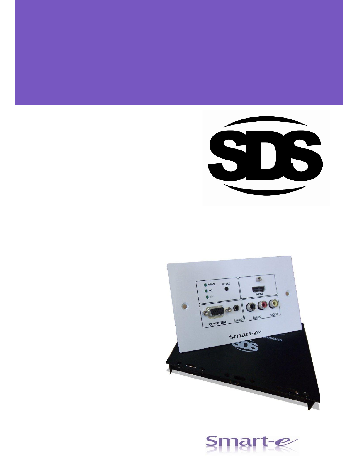
SDS-1002/3
point to point wall plate extenders
Setup guide
For more information visit our website, or talk to one of our technical team
tel: +44 (0) 1306 628264 www.smart-e.co.uk
SDS- 1002 & 1003 SETUP GUIDE
Copyright 2012 S mart-e Ltd Page 1
Page 2
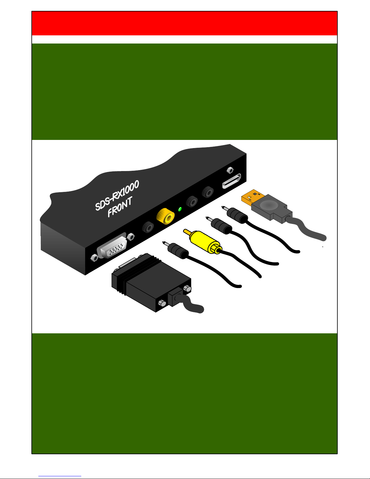
STEP 1 – CONNECTING THE SDS-RX1000 FRONT PANEL
1. First connect the video signals to the display device – RGBHV, HDMI and Composite Video (CV).
2. Next the audio, the 2 x audio outputs are the same signal from the wall plate transmitter however,
there will be separate inputs for the RGBHV and composite video so connect accordingly.
3. The RS232 connection is optional but allows for automatic input selection of the display when
each signal type is chosen, if needed the standard cable is a 3,5mm mini-jack plug to D9 plug
(Smart-e partcode CAB-JDM-1M).
The SDS-RX1000 can be programmed with the appropriate RS232 string associated with each signal
type – this is achieved by connecting to the wall plate RS232 port and running the programming
application.
SDS-1002/3 SETUP GUIDE – SDS-RX1000 FRONT
INTRODUCTION
The SDS-RX1000 is a universal receiver for all the SDS-TX1000 series wall plate transmitters. The 3 x
CAT cable connection allows simultaneous transmission of RGBHV, HDMI, RS232, a single audio channel
and remote power. The composite video and USB channel is shared on the cable therefore the SDSRX1000 has different modes depending on which wall plate is fitted.
When correctly connected to a wall plate the SDS-RX1000 receives communication identifying the type of
wall plate attached. Once this communication has occurred the appropriate LED on the SDS-RX1000 is lit
to show the ‘active’ state. On powerup all 3 LEDs may flash for a few seconds whilst communication is
established.
CV
RGBHV
HDMI
RS232
AUDIO
x2
SDS- 1002 & 1003 SETUP GUIDE
Copyright 2012 S mart-e Ltd Page 2
Page 3
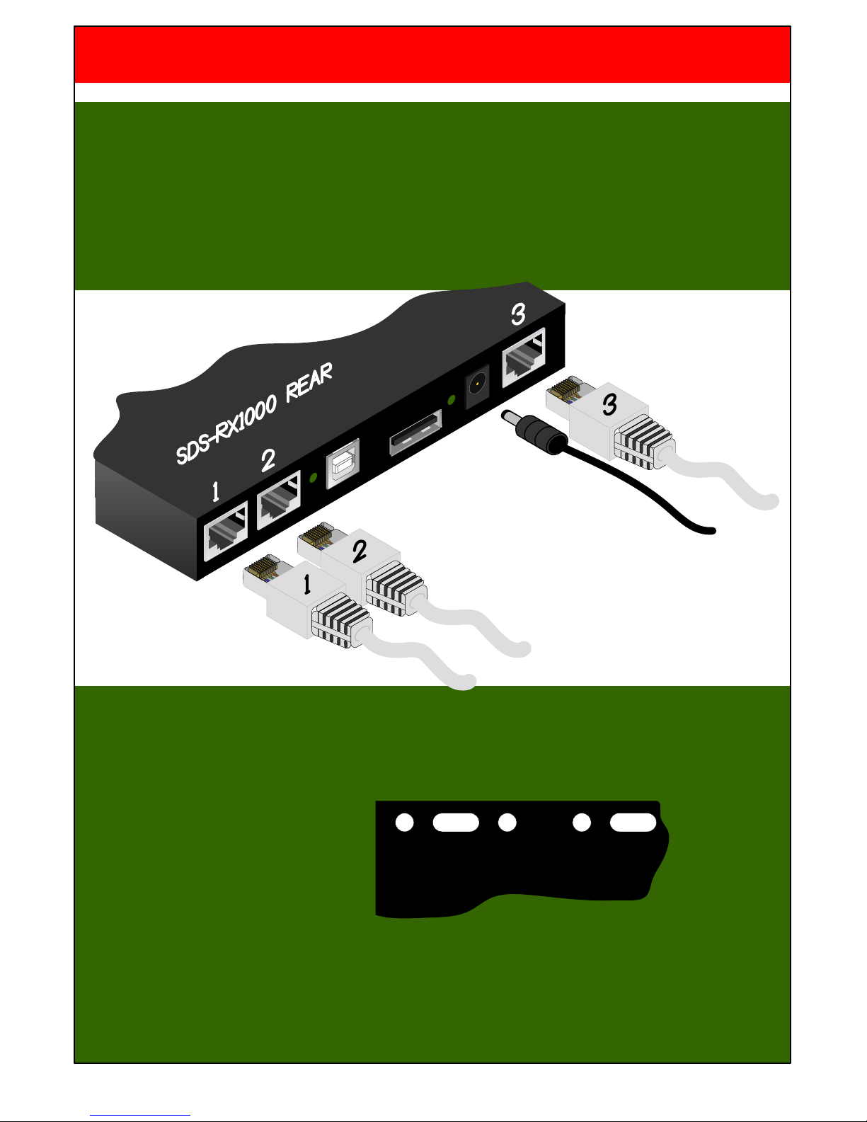
STEP 2 – CONNECTING THE SDS-RX1000 REAR PANEL
1. Connect 3 x CAT STP type cables (CAT 5-8) to the RJ45s, It is important to use Screened Twisted
Pair(STP) cable to maintain signal integrity and guarantee the full 30m specification. It is not
necessary to know the numbering of the cables as the wall plate will tell you.
2. Next connect the 12V DC PSU connector to the SDS-RX1000 and plug into the mains so the unit
powers up. One of the 3 LEDs will be lit and might not be the correct one, once a wall plate has
been connected the correct LED will be lit to show the appropriate ‘active’ function.
STEP 3 – INSTALLING THE SDS-RX1000
Now that all the cables have been connected, the SDS-RX1000 is now ready to be mounted.
1. The lid of the unit has a line of
various shaped holes stamped
into it making convenient fixing
points for either screws or cable
ties.
2. Alternatively high grade Velcro can be used to stick the unit is the most convenient place
CAT 1
CAT 2
CAT 3
PSU
SDS-1002/3 SETUP GUIDE – SDS-RX1000 REAR
SDS- 1002 & 1003 SETUP GUIDE
Copyright 2012 S mart-e Ltd Page 3
Page 4
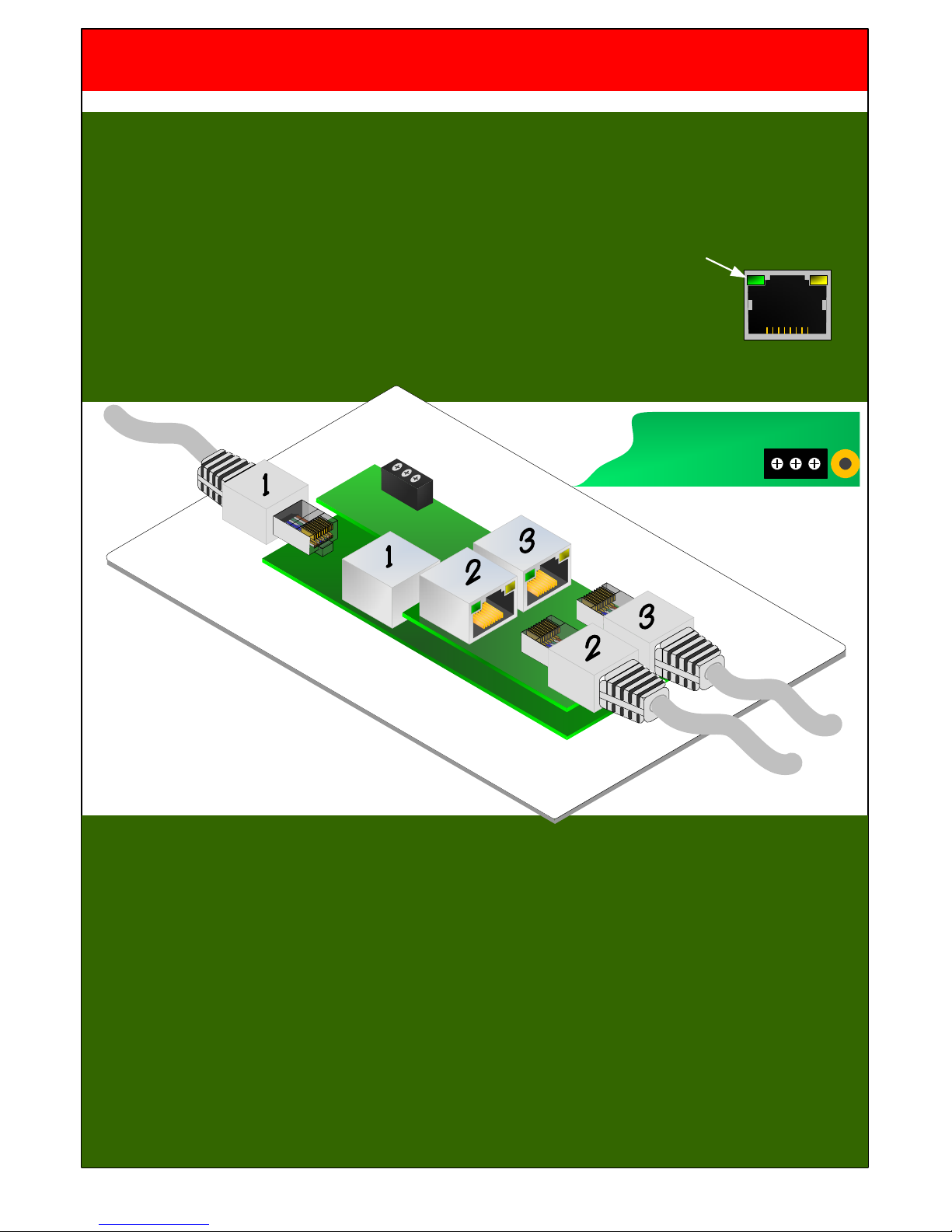
SDS-1002/3 SETUP GUIDE – STP CABLE/RS232
STEP 3 – CONNECTING THE CAT 5-8 STP CABLE
It is important to connect the Cat cables to the correct RJ45s and in the correct sequence. Firstly turn the
plate over so the PCB is on show. If the cables are not numbered then follow this sequence:
1. Connect each STP cable in turn to RJ45 number 2 until you see the green LED within the RJ45
light indicating correct connection, once found leave the cable connected.
2. Connect the other STP cables to RJ45 number 1 until its green LED lights,
once found leave the cable connected
3. Connect the last STP cable to RJ45 number 3 – note that both the LEDs on number 3 do not light
RS232
TX 0V RX
STEP 4 – WIRING FOR RS232
The RS232 port on the rear has a three functions:
1. Input selection - as well as the front panel button, RS232 commands can be sent to the wall plate
to select the required input signal type (see protocol document) ideal for integrating into a third
party control system.
2. Programming control strings – The SDS-RX1000 unit can store RS232 control strings
associated which each signal type. When a new input is selected the RX1000 will automatically
send the appropriate RS232 command switching the display to the correct format. This facility
provides a complete solution without the need for another control system.
(see programming app).
3. RS232 pass-through – The SDS units also allow RS232 commands to be passed through the
system and out putted from the SDS-RX1000, ideal for system integration.
SDS- 1002 & 1003 SETUP GUIDE
Copyright 2012 S mart-e Ltd Page 4
Page 5
CV
RGBHV
AUDIO
HDMI
AUDIO
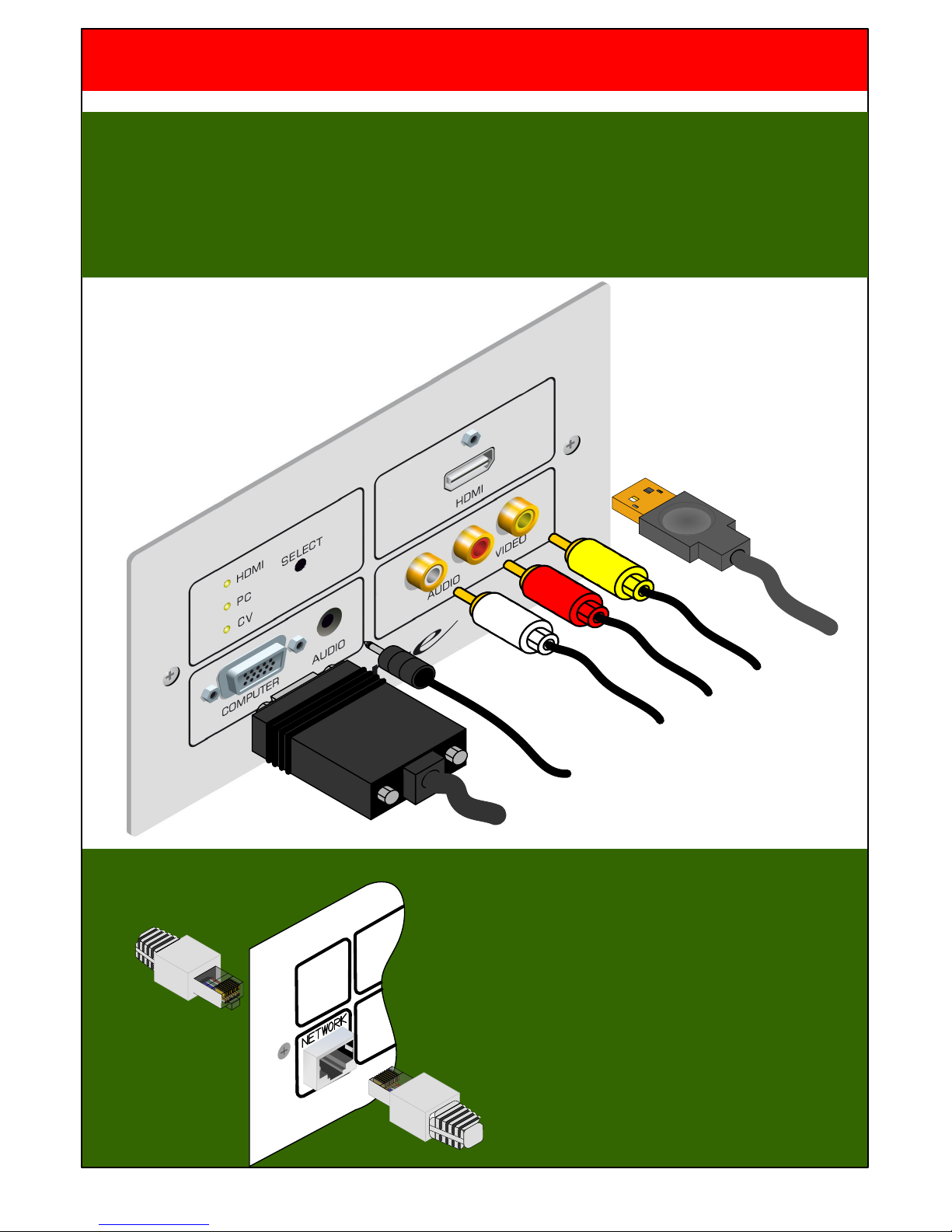
STEP 5 – ADDING THE NETWORK CABLE FOR THE SDS-1002
On the SDS-TX1002 there is an additional
RJ45 connector on the wall plate. This is for a
direct Ethernet connection which requires a
fourth CAT cable. The connection is a back to
back RJ45 coupler allowing Ethernet signals
up to 100baseT.
SDS-1002/3 SETUP GUIDE – AV SOURCES
STEP 4 – ADDING THE AV SOURCES
1. On power up with no video signals present the wall plate status will be in HDMI mode, flashing the
2. HDMI status LED. Connecting a valid HDMI source will stop the HDMI LED flashing leaving it
continuously lit and the HDMI image should be seen on the display (if the display is on the correct
signal input).
3. Next connect the RGHV cable followed by the audio and CV if required.
SDS- 1002 & 1003 SETUP GUIDE
Copyright 2012 S mart-e Ltd Page 5
Page 6

The ‘SELECT’ button toggles around the inputs selecting both the DDC and audio signals respectively. The
status LEDs indicate the selected input together with which audio in being transmitted.
STEP 6 – INPUT SELECTION
The SDS-1002/3 extends three different video types to the display. Although all three are transmitted
simutaineously, the DDC and audio channels are shared therefore, the system needs to know which signal
should be displayed.
SDS-1002/3 SETUP GUIDE – INPUT SELECTION
AUDIO AUDIO VIDEO
CV
HDMI
PC
SELECT
HDMI
HD15
SOCKE
T
COMPUTER
CV
HDMI
PC
SELECT
HDMI
AUDIO
CV
HDMI
PC
SELECT
HD15
SOCKET
COMPUTER
AUDIO
CV
HDMI
PC
SELECT
AUDIO VIDEO
1. HDMI and Audio
2. RGBHV and Audio
3. Composite video and Audio
SDS- 1002 & 1003 SETUP GUIDE
Copyright 2012 S mart-e Ltd Page 6
 Loading...