

SMART desks VISTA Assembly & Instruction Manual
ASSEMBLY INSTRUCTION MANUAL
™
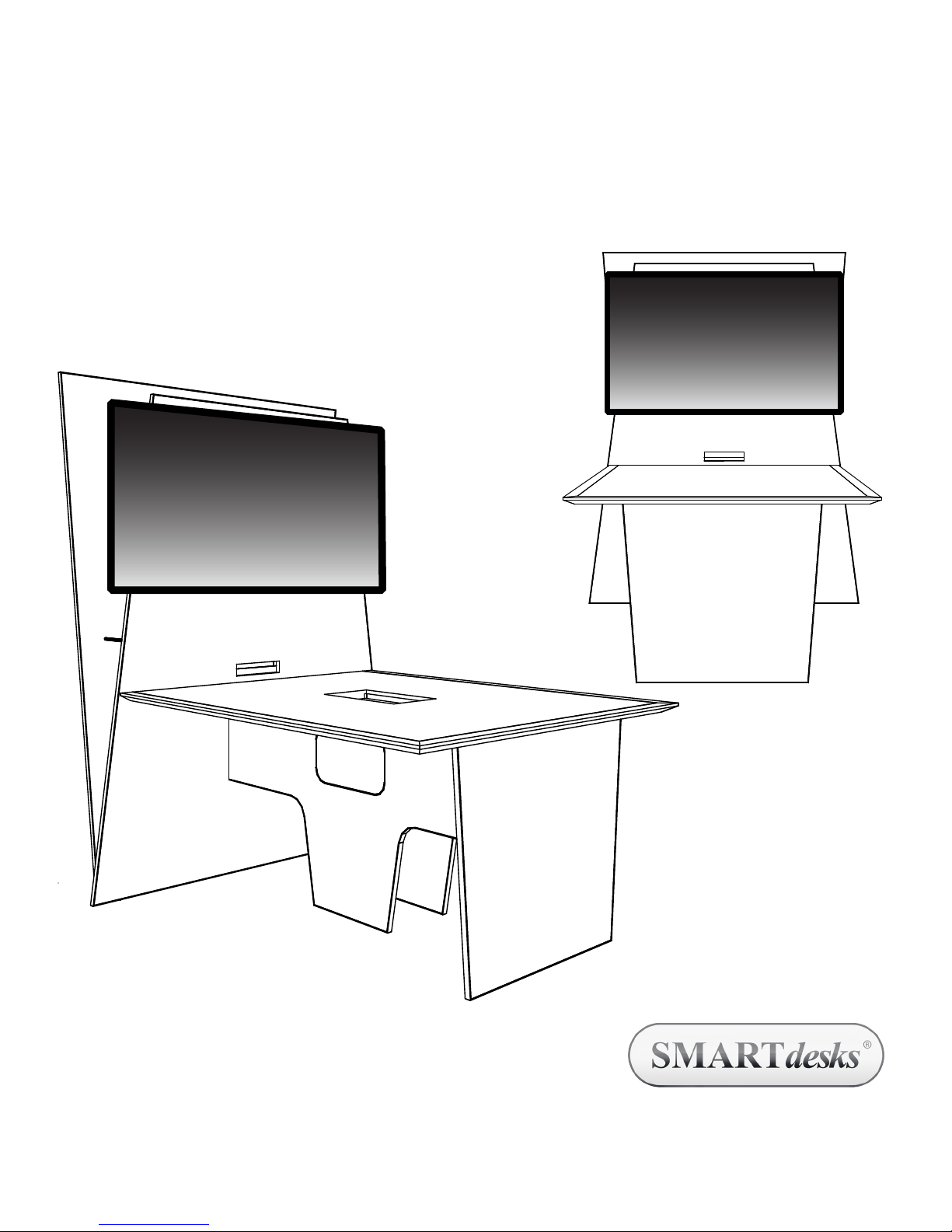
VISTA Video Collaboration Table
Typical
Assembly requires two people working together.
Video monitor and mounting bracket are not included and separately
purchased. Refer to your manufacturer’s video monitor mounting
bracket instructions for wall mounting to VISTA’s freestanding wall.
©2013 CBT Supply, Inc. dba SMARTdesks® All rights reserved.
SMARTdesks® is a registered trademark of CBT Supply, Inc.
www.smartdesks.com
800 770 7042
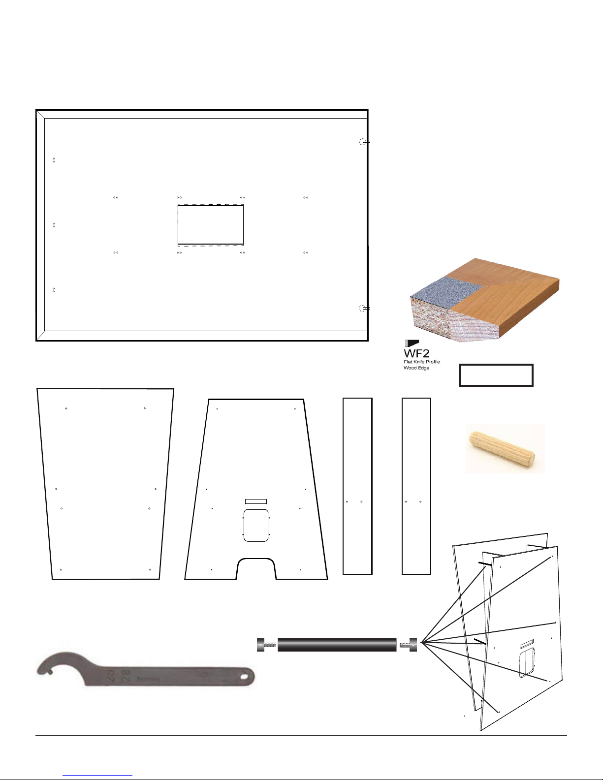
PARTS IDENTIFICATION
Please note that the VISTA Video Collaboration Tables for this installation
are NOT THE SAME. Each has been customized for its installation space. Be
sure that your parts are for the same MARK NUMBER.
One top banded on 3 sides
• Dimensions 72 x 50
• Top finish #7285-58 Violin Figured
Annigre
• Wood edge maple hardwood
stained to match
#7012-58 Amber Maple
• WF2 Edge Profile
Trapezoidal Back Wall
56w x 78h
Trapezoidal Front Wall
Fixed Pin Spanner Wrench
Used for tightening the Stand Off Bar End Caps
58.75w x 74h
Shelf (1 each)
9 deep
26 wood Dowels
12 per each vertical x 2
= 24 and two for each
equipment shelf = 26
Uprights (2 each)
11.5 w x 74h
Stand-Off Bars (6 each)
11.5” long x 1” diameter with threaded
inserts, plus 2 each tapped end caps.
Black Aluminum.
800 770 7042 SMARTdesks Technical Assistance 2 www.smartdesks.com
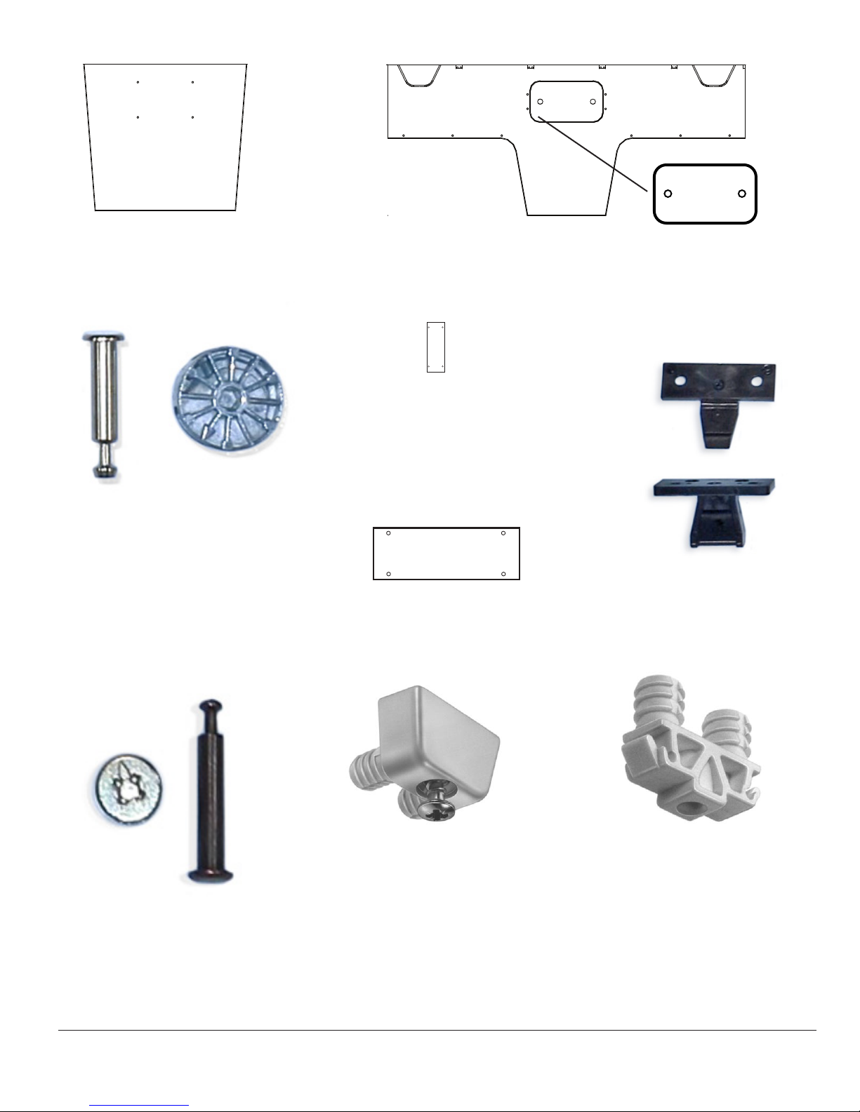
Table End Base
Thispartfastenstosidepanelsandkeel
Panel(1 each)
Maxifix End Pin
262.87.781
Maxifix Cam
262.87.003
Keel Side Panels
2 total quantity
Keel Stretchers
4 total quantity
Access Panel
2 total quantity
Male
Female
Maxi Fix End Bolt Pins 2 to go through
wall into wall end top
MaxiFix Cams 2 for tops
Minifix Cam
262.26.623
Mini Fix Pins 24 total = 8 for wall
panels (4) and equipment shelf
ends (4); 8 for Keel Bottoms; 8 for
stretchers in Keel.
Minifix End Pin
262.27.163
Keku Clips
Keel Bottom (2 for each table top)
4 total quantity
Surface Connector Female
262.70.431
This part fastens to side panels
and keel.
Surface connectors cannot be removed from their mounting holes. The females
will ship installed and the males will need to be inserted. This is done to reduce
confusion in assembly.
Surface Connectors : 9 per top, 3 each side of Keel (6); (3) on End panel.
Surface Connector Male
262.70.413
This part fastens to underside
of top.
800 770 7042 SMARTdesks Technical Assistance 3 www.smartdesks.com
Approach to Assembly
VISTA must be assembled in this order
to facilitate the installation of equipment. Coordinate with your IT specialists
so technology can be installed at the
proper stage. Assembly should be done
as close as possible to the final installation position to avoid putting stress on
the components.
1. The Keel Base Assembly is made
first, consisting of two Keel Side
Panels, one Table End Panel, and the
Keel Bottoms.
2. The Front Wall is tied into the Keel
Base Assembly so that it is freestanding.
3. Uprights and Shelf are applied
4. IT Specialists install components
and video monitor mount (not included). The video monitor mount
has its own installation instructions
for mounting to a wall. The VISTA
front wall should be structurally
sound for the load if robust bolts,
washers and nuts are used for
through bolt fastening. Installation
with wood screws is not recommended.
5. With VISTA in final position, install
the Table Top to the base and wall.
6. The very last thing to be installed is
the back wall. When installed there
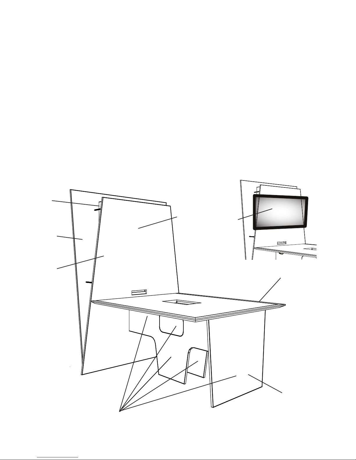
Orientation for assembled VISTA MARK 16 C
Uprights
and Shelf
is limited access to technology on
the shelf and the monitor mount.
To make changes to the technology
installation, the back wall should be
removed for service
7. If the VISTA needs to be moved to a
different location, disassemble and
reassemble in the desired location.
Monitor and Mount
attach here
Back Wall
Front Wall
Table Top edged 3 sides
End Base Panel
Keel Base Assembly
800 770 7042 SMARTdesks Technical Assistance 4 www.smartdesks.com
 Loading...