

SMART desks Cirrus Ratchet Leg Stand Up Desk Assembly & Instruction Manual
SYM ECN DATE BY CHANGE
B
268 DS Dimension A was 4.026/06/12
DRAWING#
REVISION
SHEET
OF1 1
ASY 1131
B
Parts List
DescriptionQtySeq
Genu-Flip Assembly LH11
Genu-Flip Assembly RH
12
Genu-Flip Swing Arm Assembly
13
Screw #12 X 1 PPH224
Screw 5/16-18 X 3/4" BHCS
45
End Base Assembly
26
A
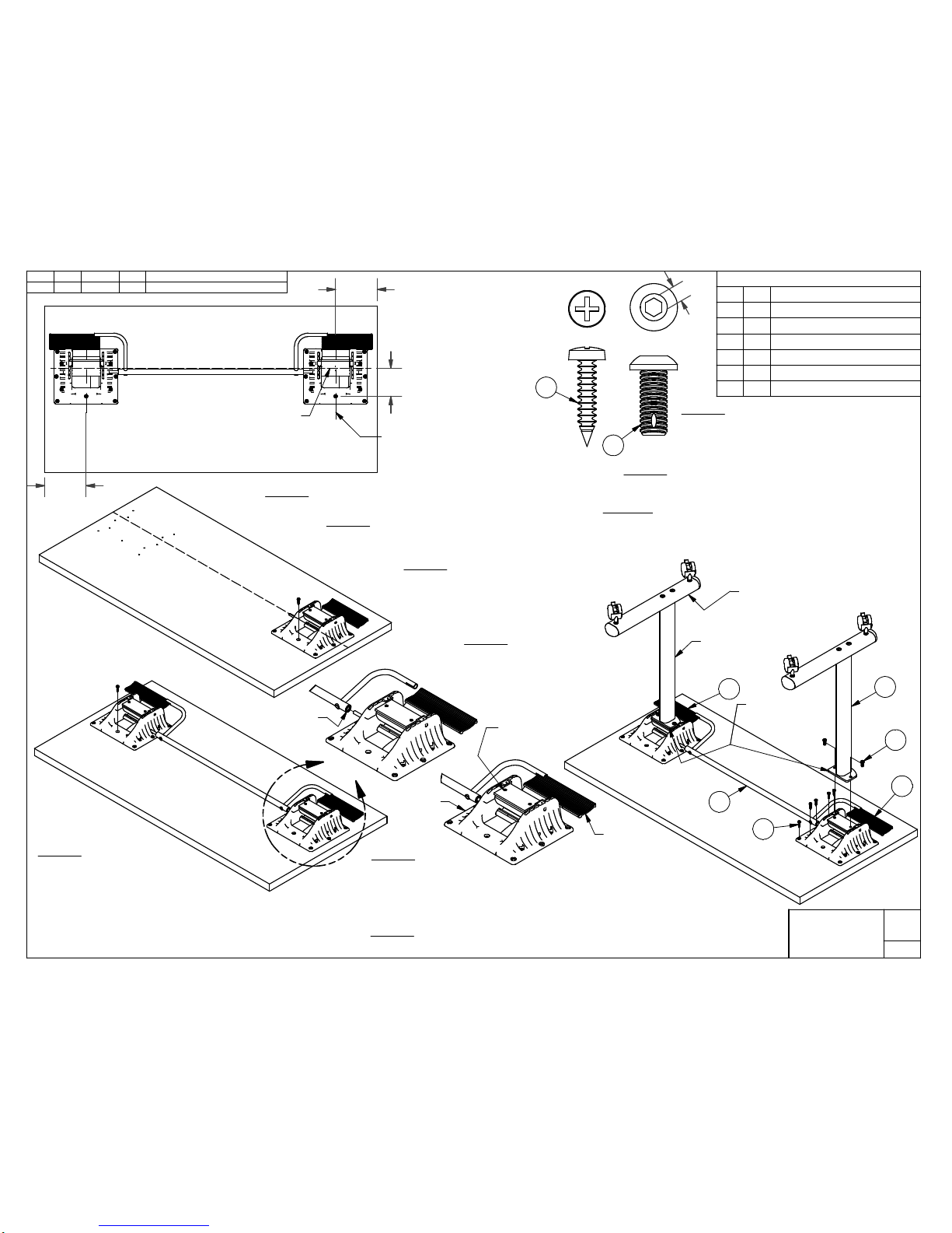
6.00
Standard Distance from Edge
of Top to Center of Bases Shown
Dimension May Vary By Job
Desired Centerline of Bases
(View Shows Bases Offset 3"
From Centerline of Table Top)
Step # 1
Position Top Upside Down On Carpet or Other Non-abrasive Surface.
Step # 2
If Top Not Predrilled, Mark and Drill Two Ø1/8 Pilot Holes
1/2" Deep at the Locations Shown In View A.
Step # 4
Place the LH Genu-Flip Assembly (#1)
Onto the Top at Desired Location and
Attach It to the Top with One #12
Screw (#4) as Shown in View B.
Step # 10
Align the Two Thru Holes In One of the End Base Mounting Plates With
the Two Tapped Holes In the Genu-Flip Pivot Block. Hand Start a
5/16-18 Screw (#5) Thru the Mounting Plate and Into Each Tapped Hole.
Then, Using a 3/16" Hex Driver, Tighten Each 5/16-18 Screw To Between
20 and 25 Foot Pounds. Repeat Process for Each Base.
2
1
3
6
5
4
4
5
0.19
Step # 5
Align Center Bushing of
Swing Arm Assembly (#3) with
5/16 Diameter Pin That Extrudes Out
From the LH Genu-Flip Assembly (#1) and
Align the Center of Formed Tube on Swing Arm
Assembly with the the Rounded Profile of the Handle.
Slide Swing Arm Assembly Onto the LH Genu-Flip Assembly
Until the End Of Bushing Is Flush With the Edge of Genu-Flip Housing.
Step # 3
Verify That the Pivot Block In Both Genu-Flip
Assemblies Are Positioned As Shown Below.
If Not, Press the Genu-Flip Handle Down to
Allow the Block to Pivot and Rotate the Block
to This Position.
Handle
Pivot Block
With Two Tapped
Holes Up
6.00
Step # 8
If the Top Was Predrilled, Install the Remaining #12
Screws (#4). If the Top Was Not Predrilled, Use the
Genu-Flip Housing as a Template and Drill Ø1/8
Pilot Holes By 1/2" Deep Before Installing the
Remaining Screws.
If Installing Cantilevered End Bases,
the Shorter Side of the Mainbar
Needs to Be Positioned
Towards the Handle.
Genu-Flip
Housing
Step # 6
Using the Same Method as
Step #5, Align the RH Genu-Flip Assembly (#2) with the Other End of the Swing
Arm Assembly (#3). Slide the RH Genu-Flip Asssembly Into Swing Arm Assembly
Until the Pilot Hole in the Top Lines Up With the Hole In the Genu-Flip Housing as
Shown In View C. Install a #12 Screw (#4) to Secure Genu-Flip to Top.
Center Bushing
of Swing Arm
End Base Styles May
Vary From the
One Shown
View A
View B
View C
Step # 7
Verify That the Two Genu-Flip Assemblies Are Inline with Each Other.
Step # 9
If Not Already Pre-Assembled, Assemble the End Bases Per the
Base Assembly Instructions.
Mounting Plate and
Pivot Block Flush
on This Side
Up to 2.00 wide Column A = 4.02
2.13 to 2.50 wide Column A = 4.27
2.63 to 3.00 wide Column A = 4.52
3.63 to 4.00 wide Column A = 5.02
SYM ECN DATE BY CHANGE
A
-
DS
New Drawing
10/24/12
DRAWING#
REVISION
SHEET
OF1 1
ASY 1173
A
Parts List
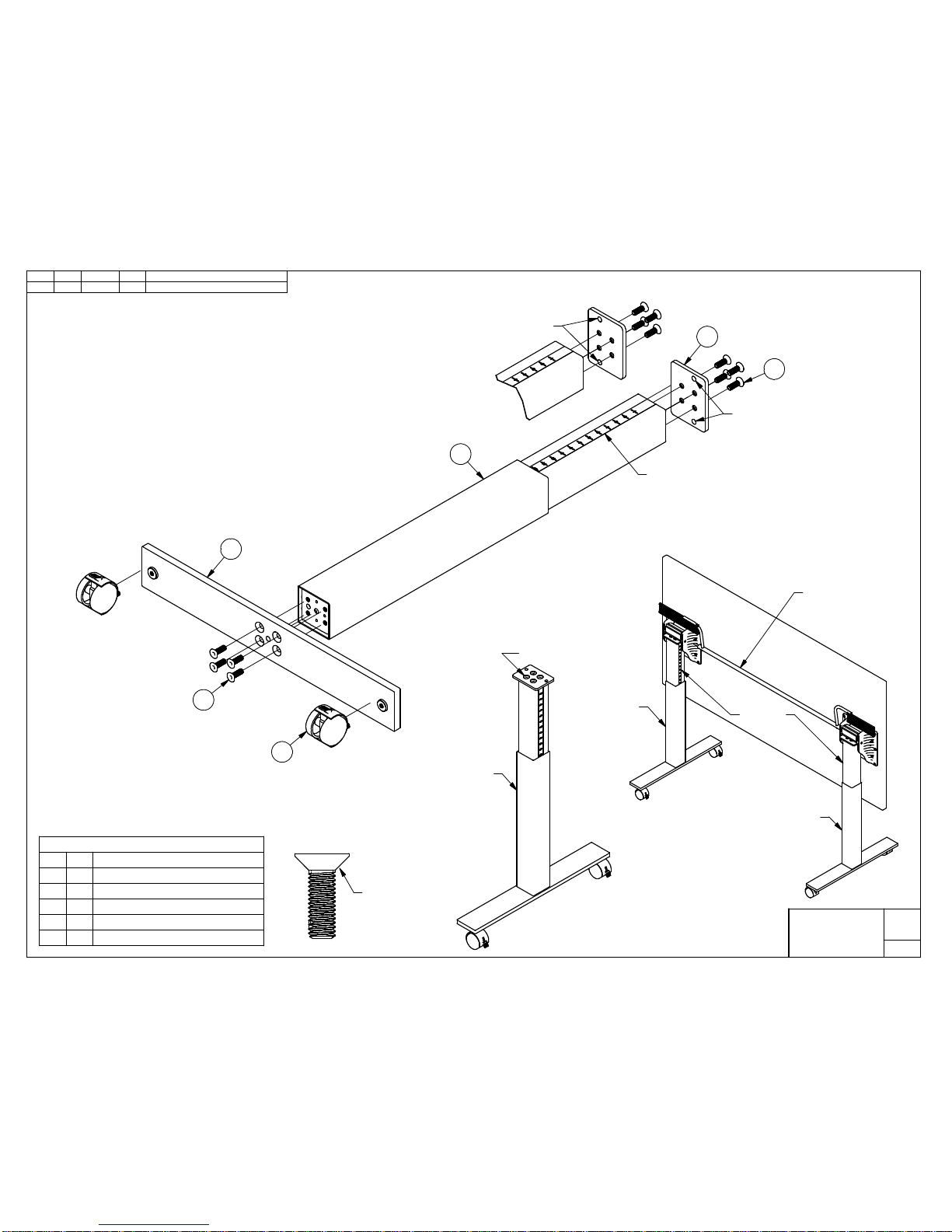
DescriptionQtySeq
Mounting Plate11
Column Assembly, Ratchet
12
Mainbar Assembly
13
Screw, M8 x 25mm FHCS Hex Drive84
Leveler or Caster
25
M8 x 25mm
ASSEMBLY INSTRUCTIONS
1. Align the Four Holes in the Mounting Plate (#1) with the Four Tapped
Holes in the Column (#2). Insert Four M8 x 25mm Screws (#4) Thru
the Mounting Plate and Thread Into the Column. With a 5mm Hex
Drive, Tighten the Screws To 15 Foot Pounds of Force.
2. Align the Four Holes in the Mainbar (#3) with the Four Tapped Holes
in the Column as Shown. Insert Four M8 x 25mm Screws Thru the
Mainbar and Thread Into the Column. With a 5mm Hex Drive,
Tighten the Screws To 15 Foot Pounds of Force.
3. If Not Pre-Installed, Turn the Threaded End of the Levelers or Casters (#5)
Into the Threaded Inserts On the Bottom Side of the Mainbar.
1
2
4
5
4
3
Holes Location
for Side A
Decal for Height
Adjustment Positions
For Flip Mechanism
Assembly, See
Drawing ASY 1131
Side A
Side B
Decal
Countersunk Holes
Side A
Holes Location
for Side B
 Loading...